Prop Dragon in Noodle Bar for the larp Do Androids Dream?

IMG_024056
For the larp Do Androids Dream we needed a lot of small props to give a Blade Runner feeling of the scene.
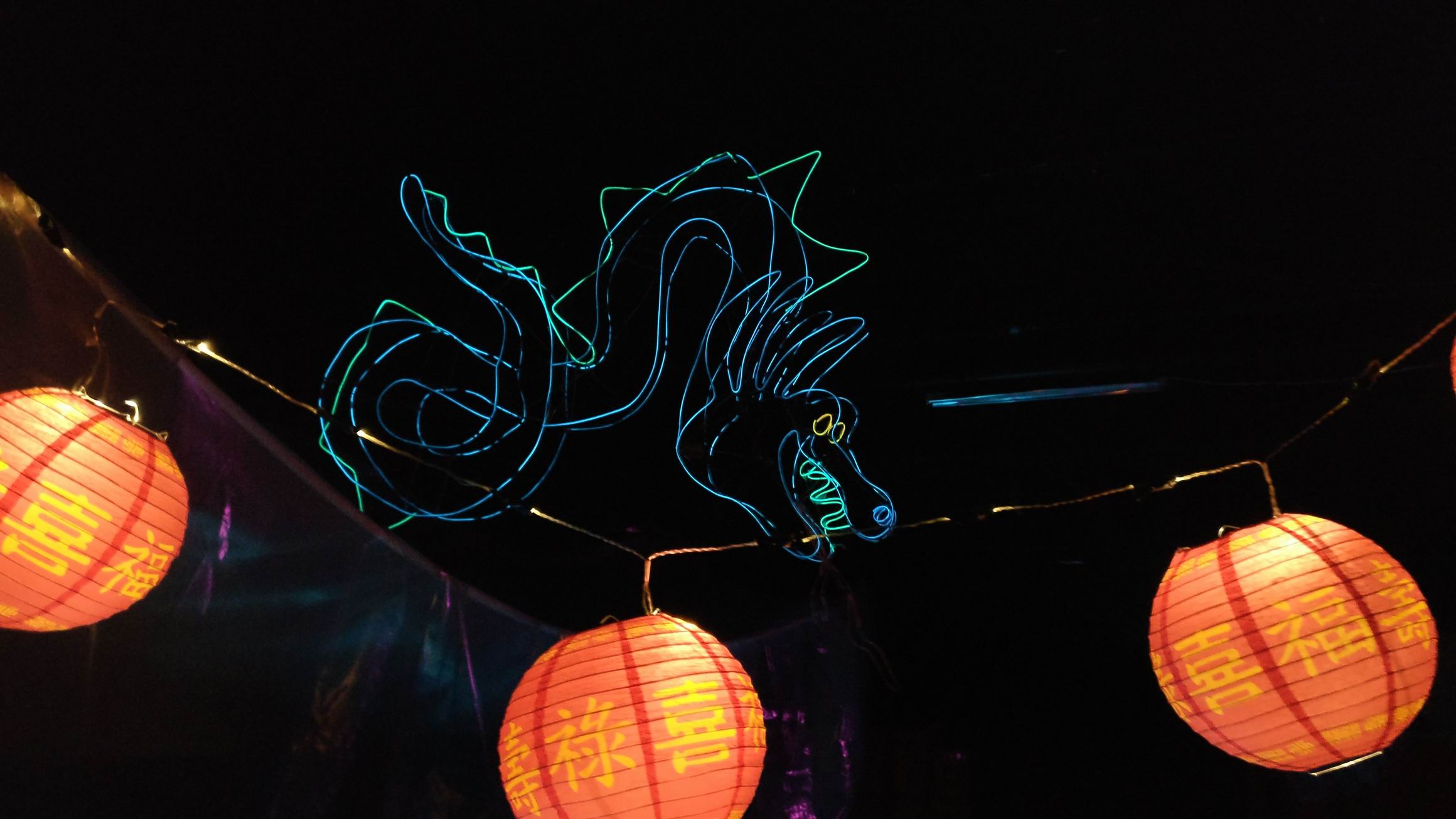
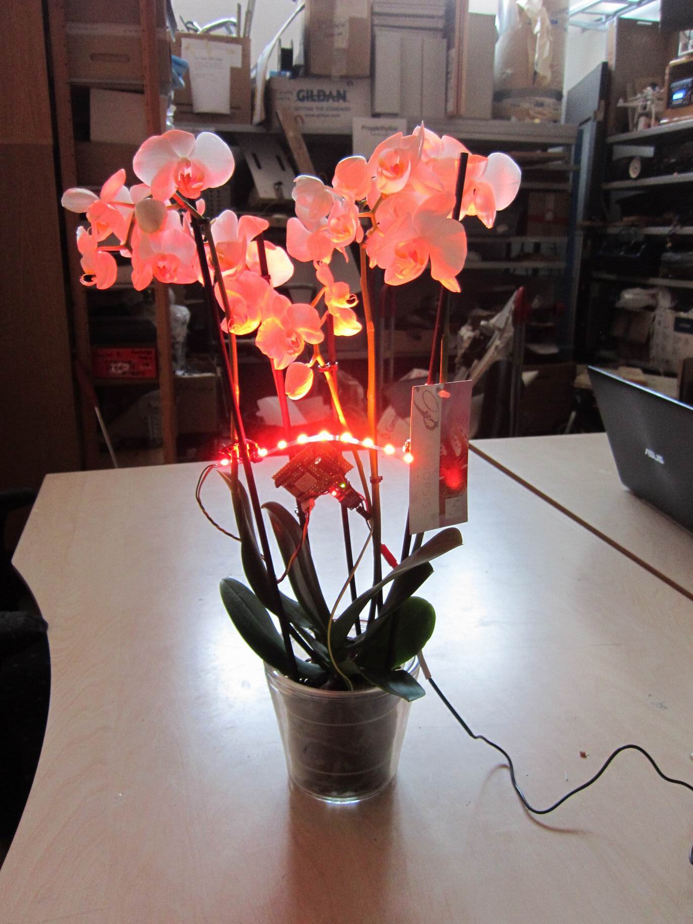
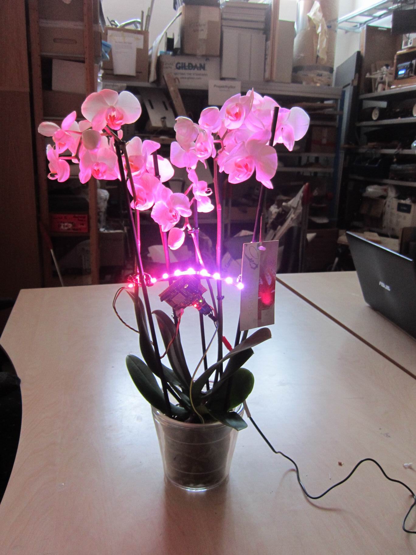
An iconic part of the movie is the dragon sign above the Noodle Bar. I thought i could be made out of el wire and it could, it even looked like neon. The light emitting from the el wire was really low doh, I would prefer to have stronger light.

IMG_024057
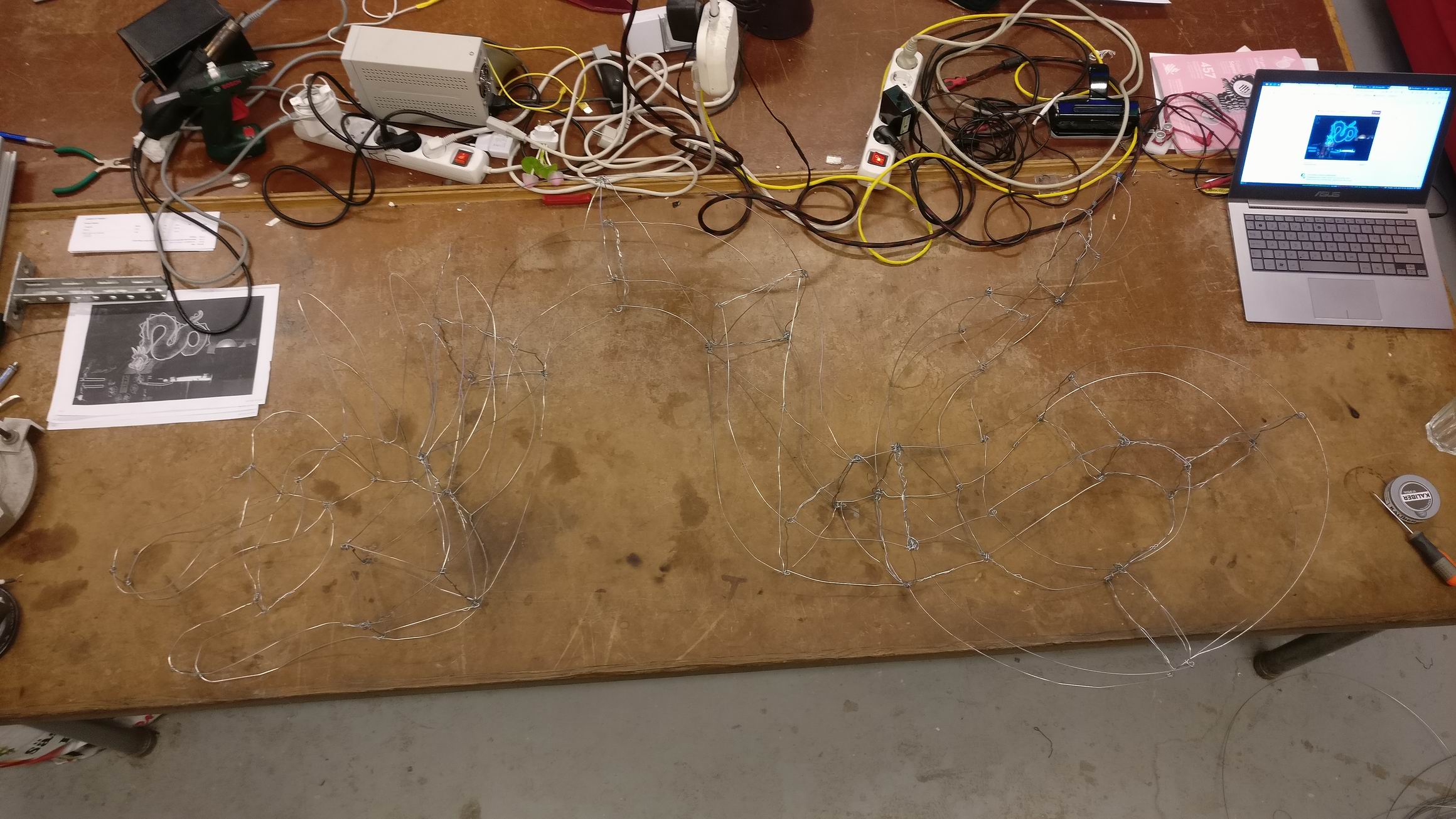
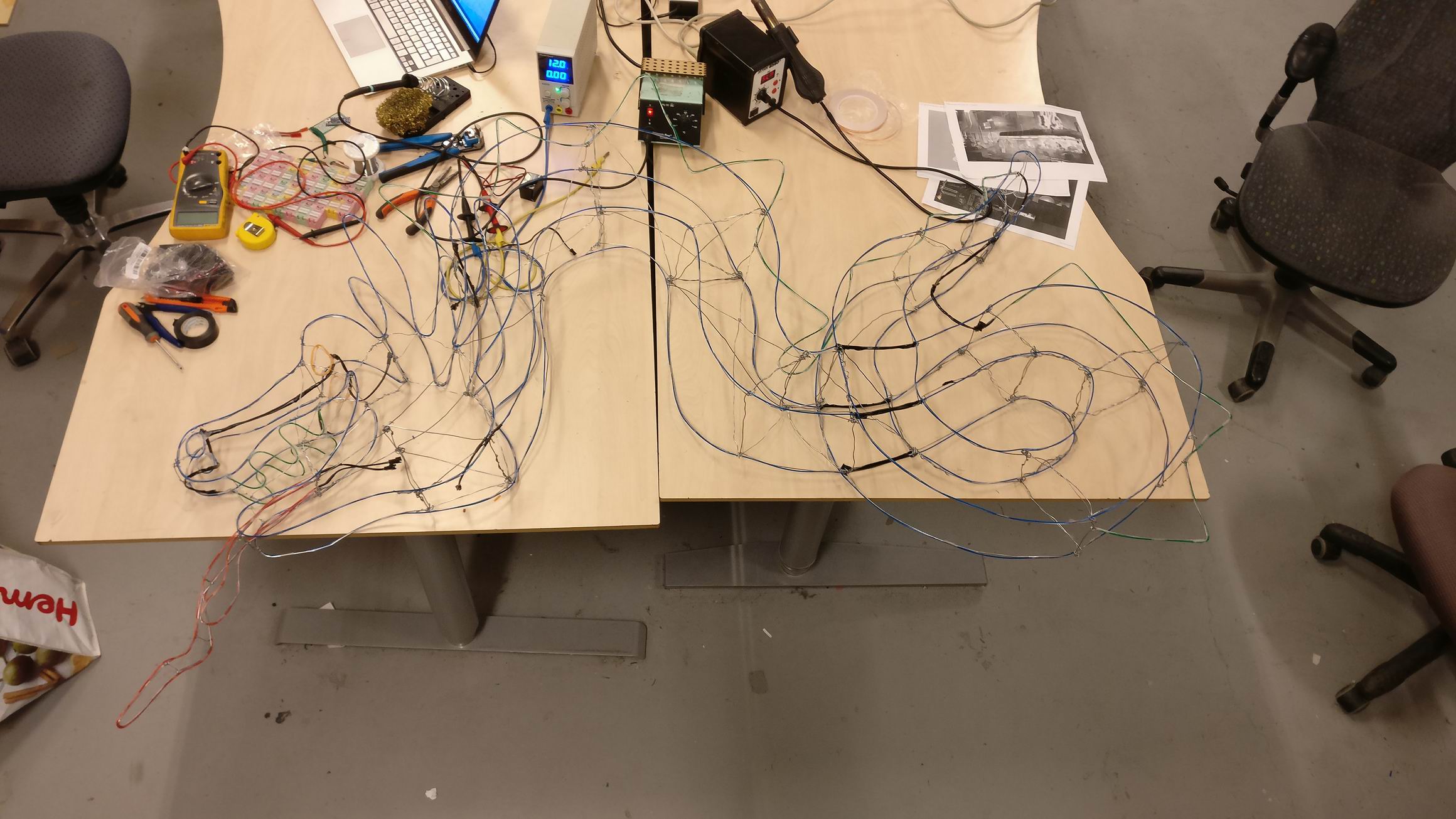
I started out by placing steel wire in the dragons shape by hand.

IMG_024058
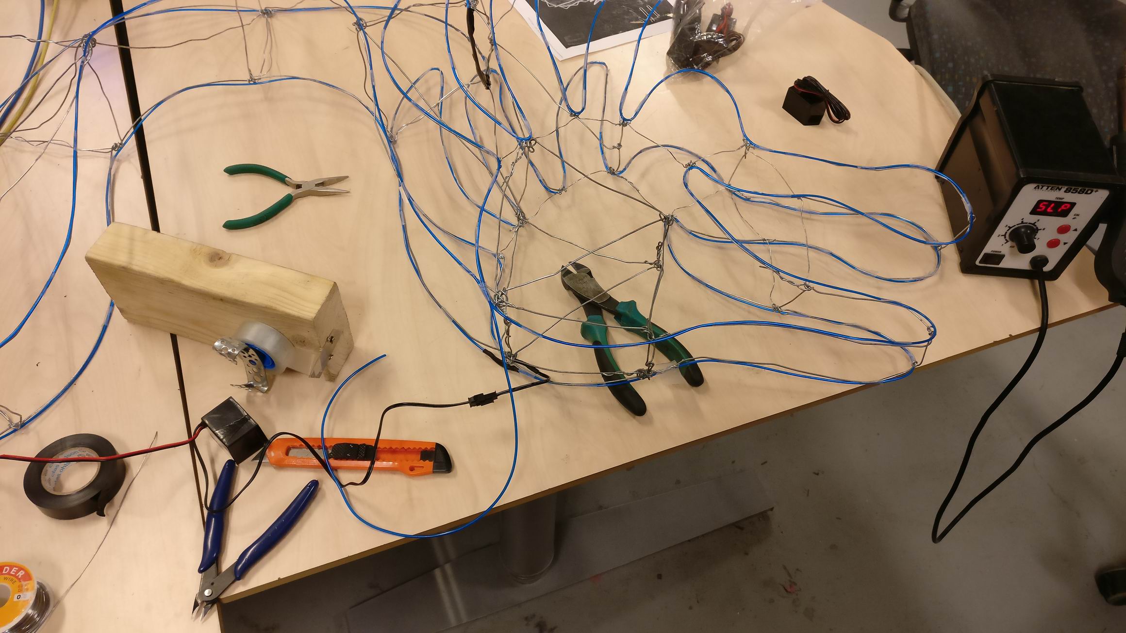
Attaching el wire around the steel wire frame was quite easy, just a matter of placing some transparent tape around it.

IMG_024059
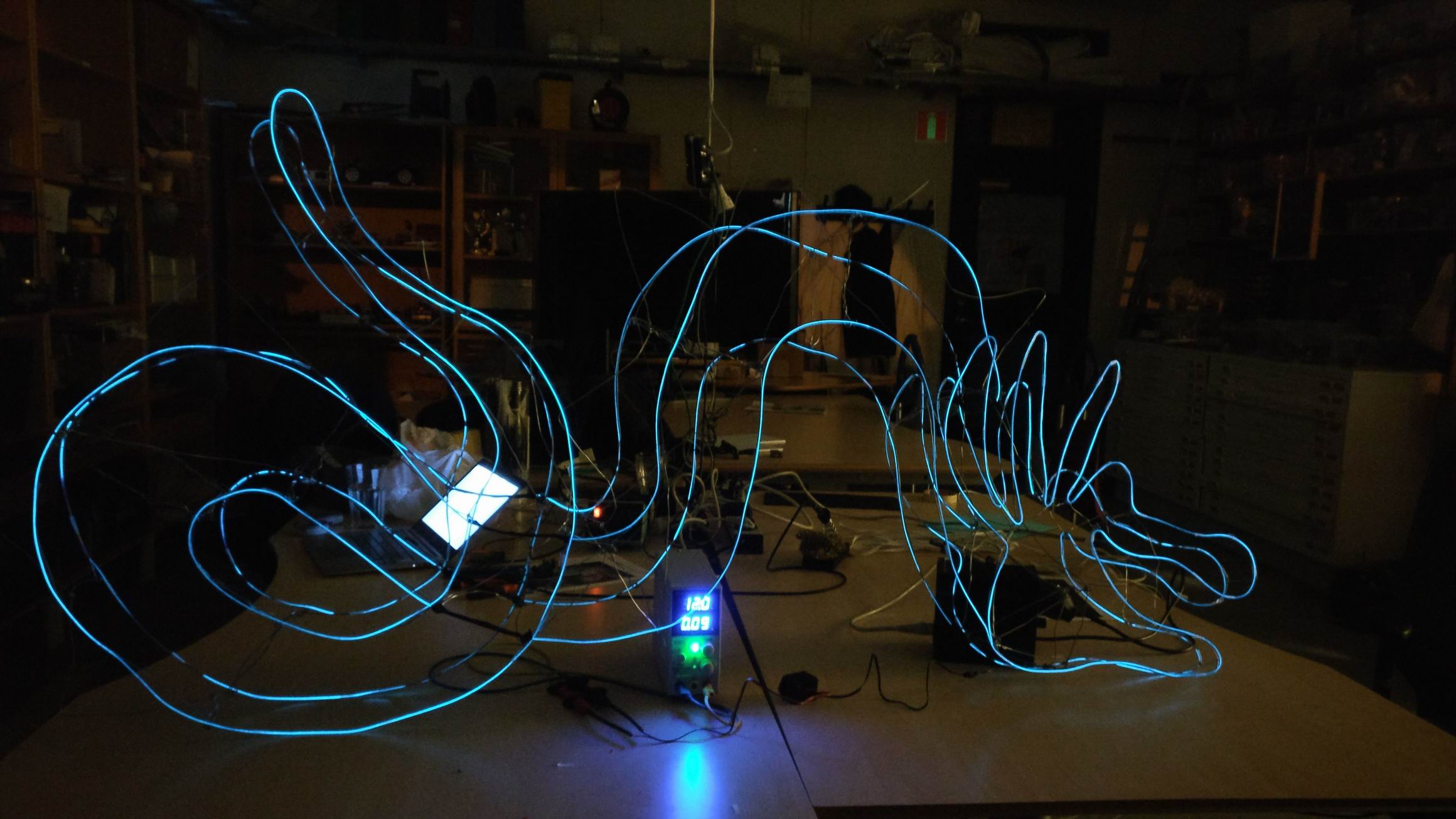
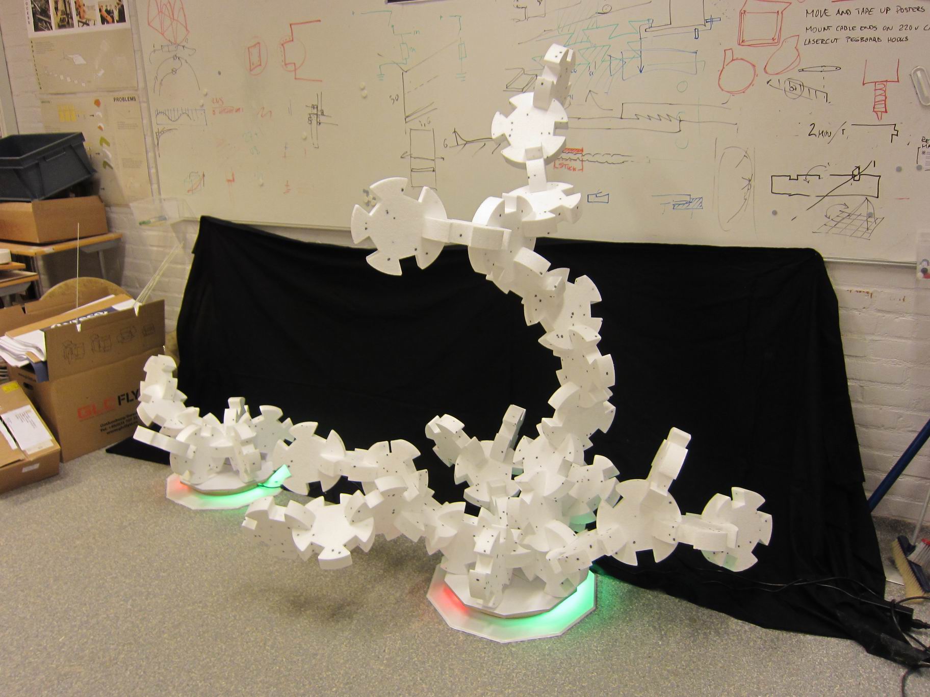
When trying out the outer shape I know I was on the right track, it looked great!

IMG_024060
IMG_024061IMG_024062IMG_024063
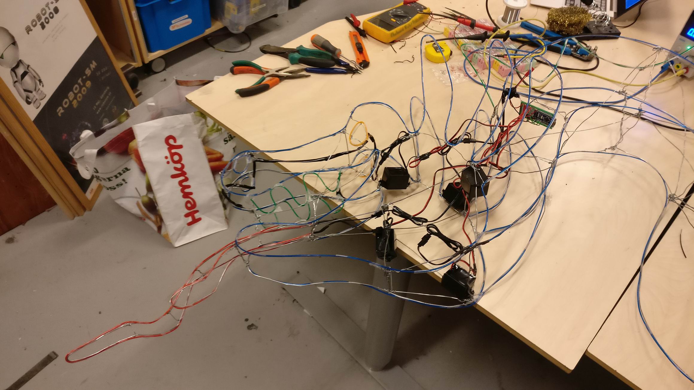
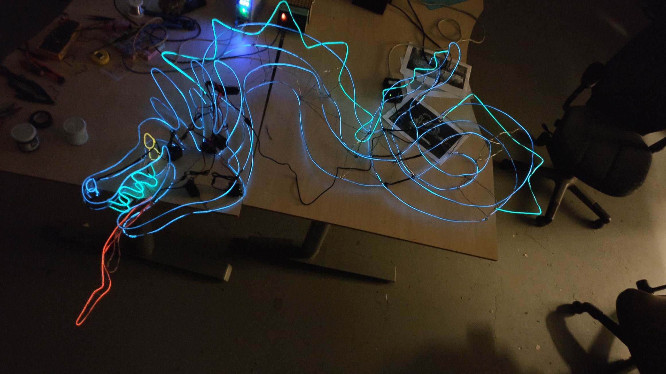
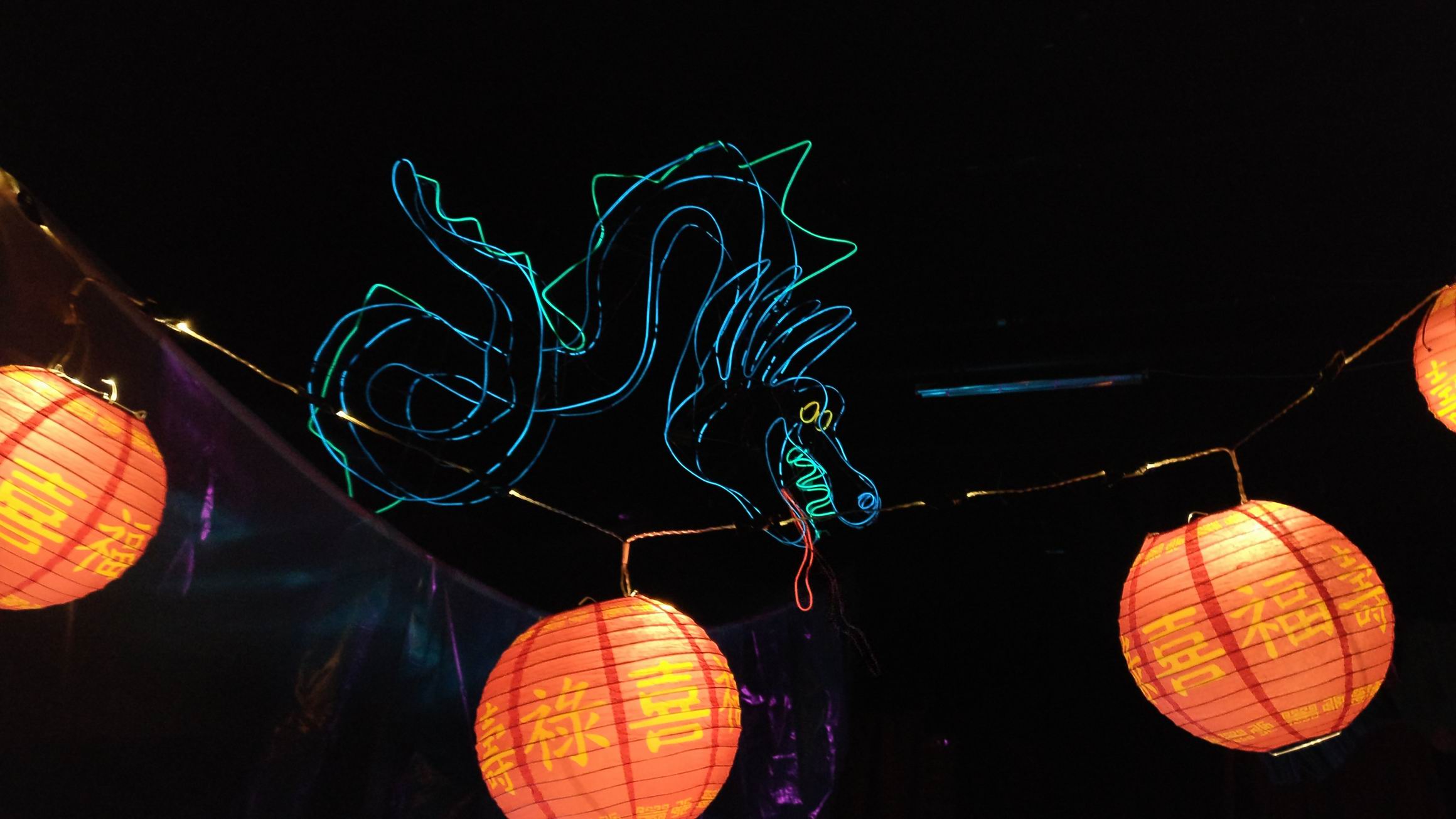
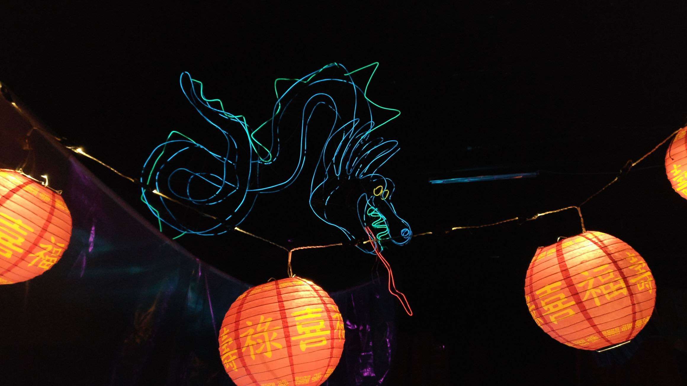
The dragons tongue is animated in the movie, it’s animated in segments. I was after the same look, so I created two segments for the tongue and had the idea the enabling each segment by turning on and off the high voltage el wire transformers.
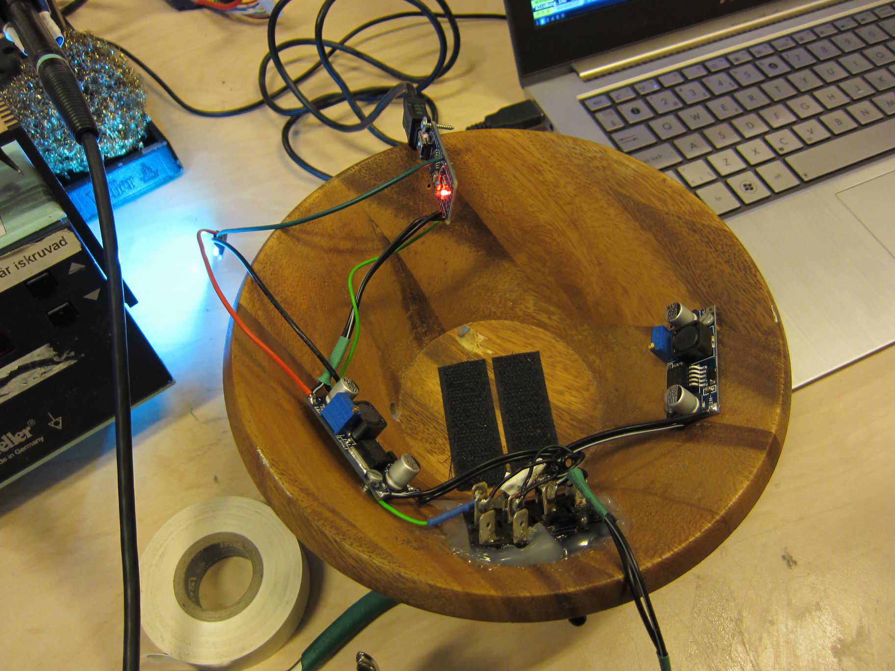
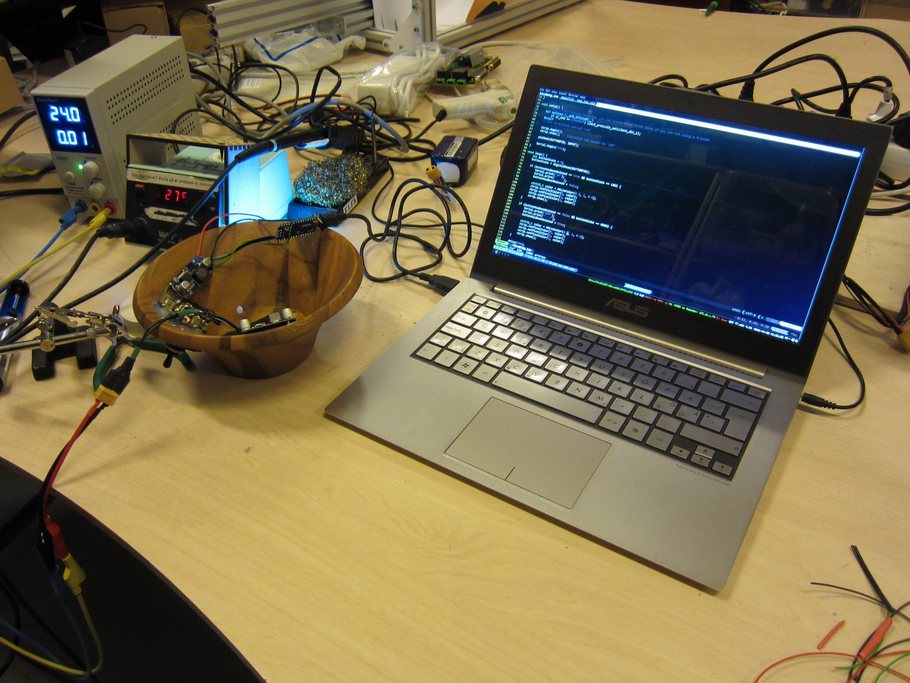
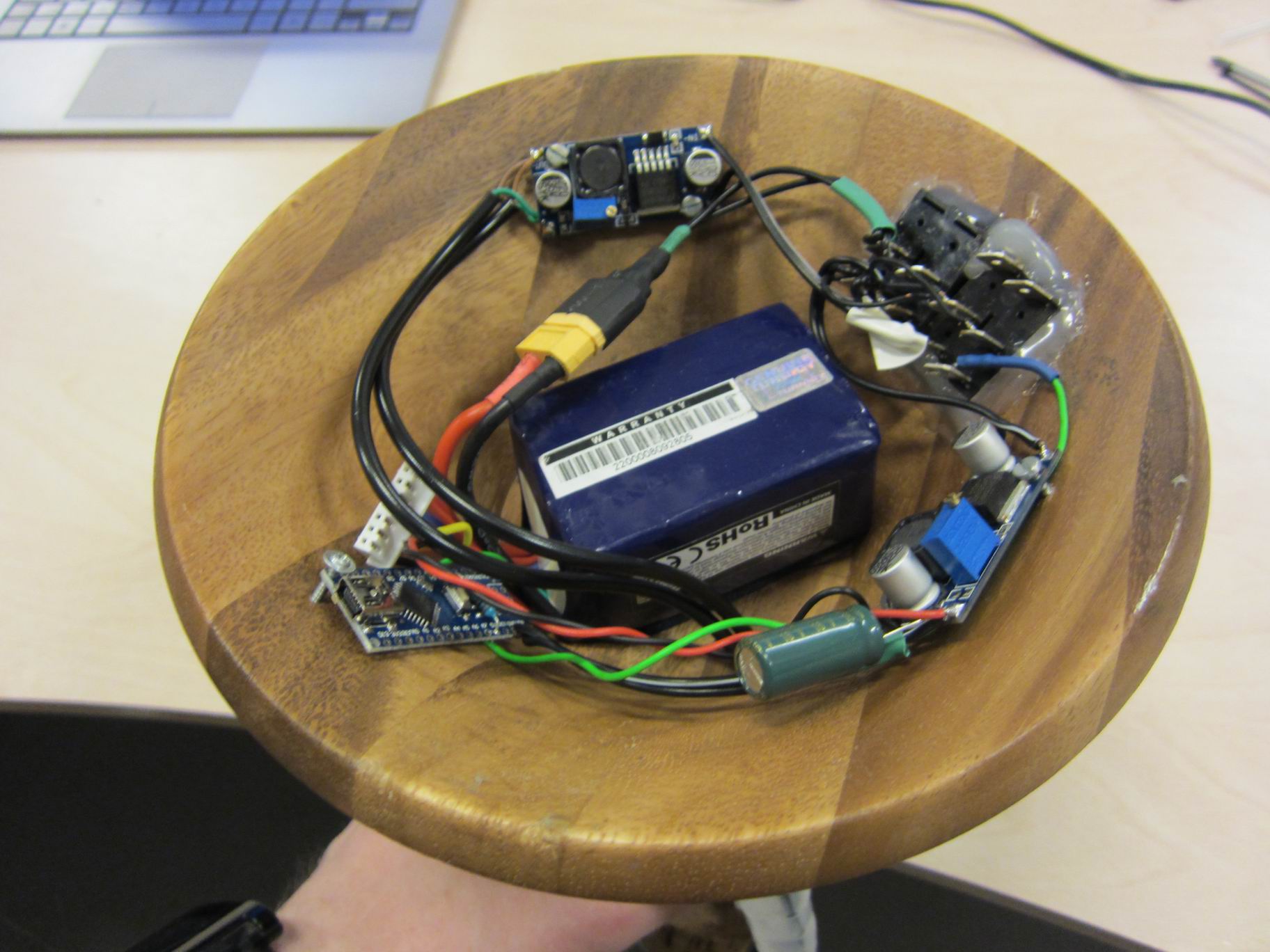
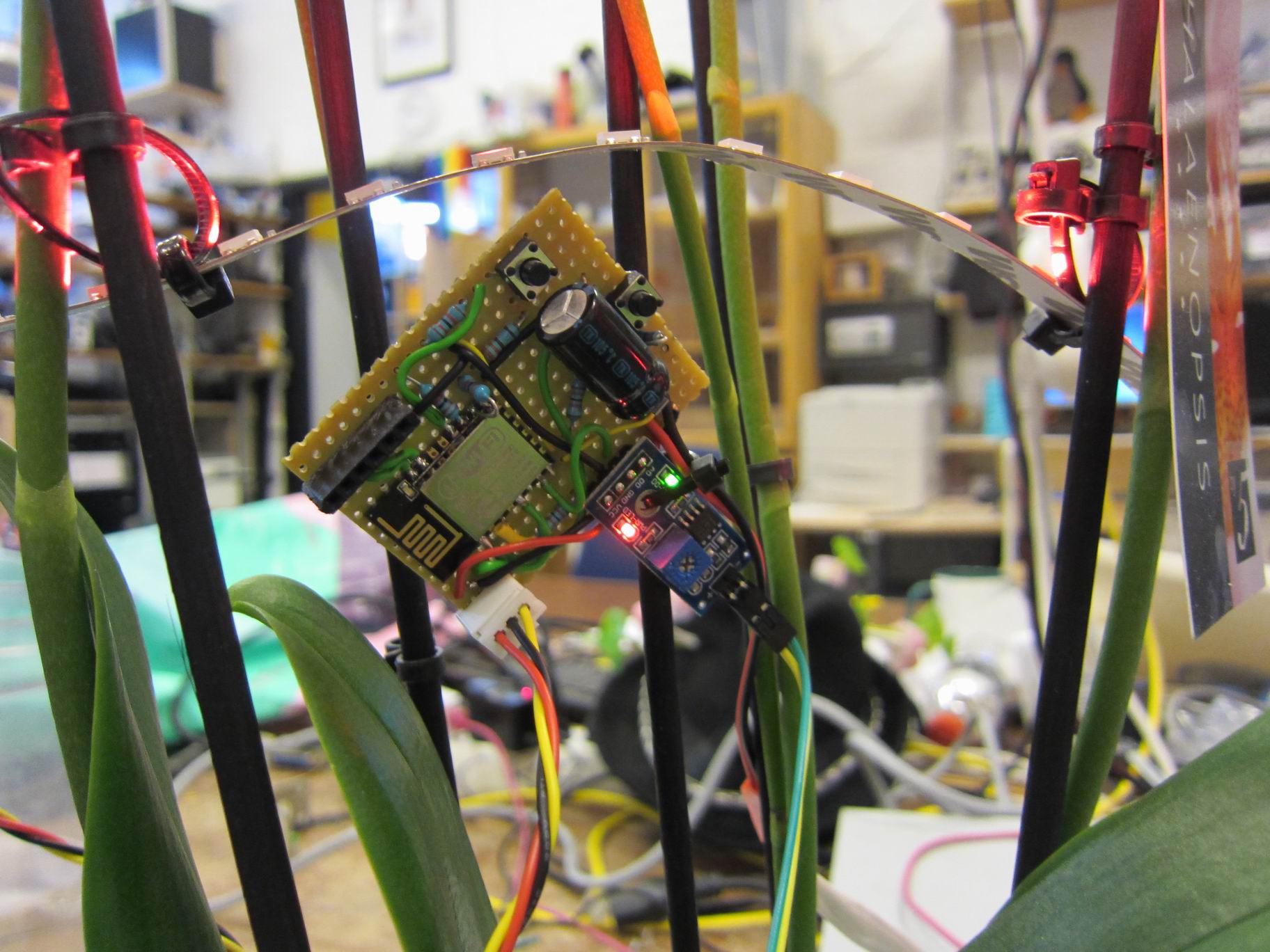
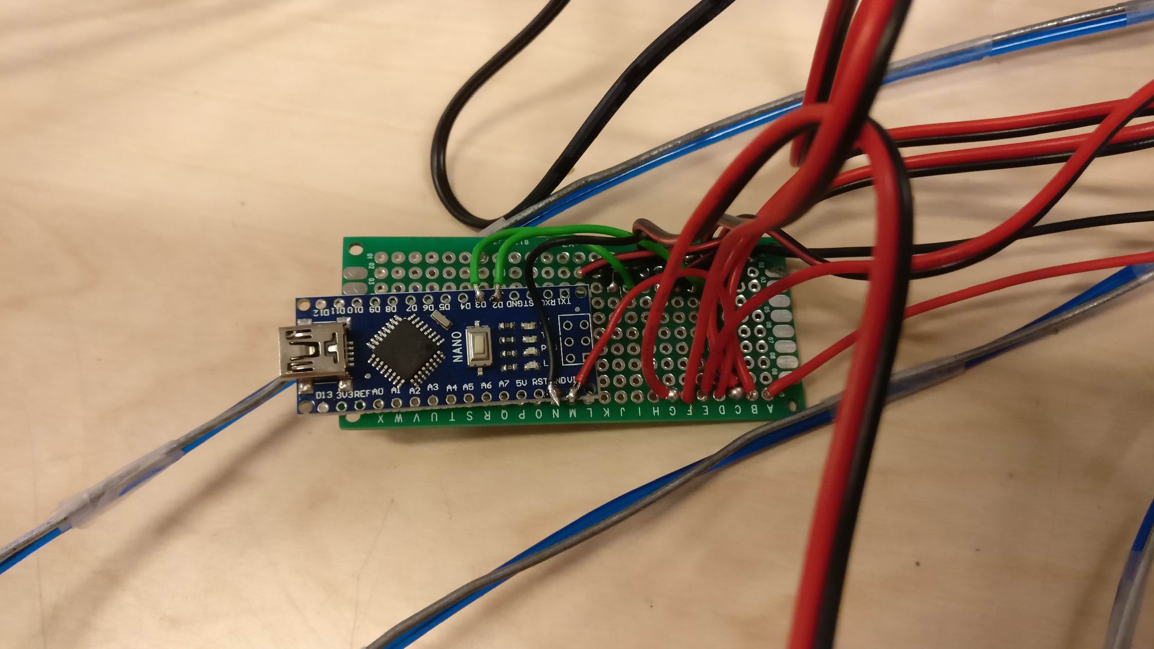
I connected a couple of N-channel MOSFET IRLML6344 and connected it to a Arduino Nano.

IMG_024064IMG_024065IMG_024066

µMute – A microwave oven silencer


I’m tired of the buzzer in the microwave oven that is beeping constant up to a minute.
IMG_20170122_0001

IMG_20170122_0002IMG_20170122_0003
So I opened it up like any normal hacker would, found the buzzer and snapped it off.

IMG_20170122_0005
IMG_20170122_0004
Sure, the buzzer was irritating, but so would be not to hear when my food is cooked. So i quickly had a look at the PCB and find a very interesting pinout.

IMG_20170122_0007
IMG_20170122_0006
So I soldered on some pins and started to measure the voltage level.
VCC of 5V looked promising for a microcontroller.

IMG_20170122_0009
IMG_20170122_0008
I had a look at the buzzer signal, it was a 2kHz signal with an amplitude of 5VDC.

IMG_20170122_0010
I had a rough idea in mind about having a small tune play instead of the 2kHz tone, and it should only play once.
So I shuffled some code together to code to play a small tune from the flash of an Arduino Nano. The flash could only hold about 18k of samples and was played at 8kHz.
https://github.com/TimGremalm/MicroMute
(inspired by http://playground.arduino.cc/Code/PCMAudio)
In lack of a better choice i choose Windows XP’s startup sound.
I shuffled some more code around to sample the original buzzer signal from a GPIO. If the sound is playing at more than 2kHz for a certain time I would trigger the sound.
I applied some time based software filters to filter out some noice.
I build a small amplifier out of an MOSFET (IRLML6344) and a small 0.5W speaker element I found at my local hackerspace.

IMG_20170122_0011
I throw it all into the chassis of the microwave oven. There was plenty of space, but i took some precautions to electrically isolate the PCB and speaker.

Unfortunately the sound from the small 0.5W element was too low. It barely was distinguishable against the sound of the microwave ovens fan.

IMG_20170122_0014
IMG_20170122_0015IMG_20170122_0012IMG_20170122_0013
IMG_20170122_0017IMG_20170122_0018
So I upgraded the element for a 3W element that I found in an old PC speaker, and took some precautions and upgraded my amplifier as well for the more stable Class-D amplifier PAM8403.

MicroMuteSchematic.sch
Schematic PDF

The sound was much louder and you can clearly hear the “Done”-sound from the microwave oven.

Alco Bong 9000

IMG_6771
This is an alcoholic bong, two ultrasonic elements forces the water into small particles that forms a mist. The elements is normally used for water in decorations or water humidifiers.

IMG_6772IMG_6774
I got this old Ikea bowl from a second hand store. It holds the electronics for driving the ultrasonic elements, as well as an MCU to drive some leds.

IMG_6773IMG_6775
There’s two systems that is powered from a single 6S LiPo battery.
The ultra sonic elements is apparently sensitive about over voltage and will fry if the voltage exceeds 24V. The first system consists of a buck that caps the fully charge voltage of 25.2V down to 24.0V. That system is activated by a momentary switch on the front.

The second system drives the RGB LED’s. A nice party bong should look good. A small Arduino Nano is driving some WS2812 RGB leds around the glass pitcher. A buck converter caps the voltage at 5V that is used by both the WS2812 RGB strip and the MCU.
The led lights is slowly breathing when the alco bong is idle, and rotates the color hue when in use.

IMG_6776IMG_6777
The glass pitcher was glued on the bottom with epoxy and seemed to bound well with the wooden bowl.

Orkide Random – A IoT flower with pretty random power

A video posted by Tim Gremalm (@timgremalm) on


Probably the most random plant in the world, it fetches a “true” random signal and display pretty colors on a WS2812 addressable LED strip.
The seed is based on one of the best randomization generators; cosmic background radiation from random.org. Yet another Internet of Things device made out of the ESP8266, the dirt cheap powerful WiFi enabled microcontroller.
IMG_6704
IMG_6705IMG_6706IMG_6707

IMG_6708IMG_6709IMG_6710IMG_6712IMG_6713IMG_6714IMG_6711

IoT Nalle dances to Twitter feed

IMG_6683
An Internet of Things enabled teddy bear that dances at filtered Twitter statuses.

IMG_6684
IMG_6685IMG_6688IMG_6686IMG_6687
To move the teddy bears arms servos is used. It’s a pretty simple setup, some extenders for the arms that is going through the real arms of the teddy bear.
The servos is quite weak, so they bearly move the arms at all.

IMG_6689
IMG_6690
Mounting of the servos.

IMG_6691
IMG_6692
The electronic setups contains of a small cheap microprocessor called ESP8266. The ESP8266 have a small WiFI-antenna integrated in the breakout board and can hook up to any access point, or even create one.
I’m running the firmware NodeMCU , it’s a real time LUA interpreter. So the firmware is only programmed once on the flash. To write your own program you just transfer them over serial UART, and the firmware will save the script on flash.
The processor is running at 80MHz so it’s pretty fast.

IMG_6693
I’m using Twitters API to fetch the latest post on a specific search term. The API gives me a detailed formated JSON file containing the time and date of the post, as well as the post.
The Twitter API is quite messy to work with, a lot of headers and authentication is required. The ESP would likly handle both the SSL and the big JSON format, but it will steal some CPU-time and it’s hard to work with. I made a PHP-proxy for the twitter feed, parsing the time and date and presenting it in unix timecode. The message of the post is stored as an MD5 hash sum.
On the IoT Nalle i keep track of the already “danced” Twitter posts and only dnaces to new posts.

IMG_6695
IMG_6694IMG_6696IMG_6697
Final assembly, a lot of hot glue and screws was used.

Interactive LED balancing board

A video posted by Tim Gremalm (@timgremalm) on


IMG_6636
IMG_6637
An interactive game were the visitors can build complex structure with help from an interactive LED balancer.
The installation was part at Vetenskapsfestivalen.

It’s a project by Stig Anton Nielsen read more about it in this post.

TeiSteadyBuilds from stig anton nielsen on Vimeo.

IMG_6645

A video posted by Tim Gremalm (@timgremalm) on

IMG_6638IMG_6643IMG_6644

The loadcells is build from 16 layers of conductive carbon packaging film. The recistance ranging from 500k to about 450 Ohm loaded at 8kg. Because it’s a so huge range the loadcells can be directly hooked up in a voltage divider, no amplifiers needed.
3 load cells us used to detect the direction and force of the balance. They are really sensitive to touch, small pressures from fingertips will be easily detected. A backside is that the film tends to be squashed so that it takes long time form the form and resistance to return.
The value from the 3 loadcells is arranged in 3 forces 120 degrees apart. The Forces is calculated into a resultant that is describing a thrust vector.
The thrust vector is indicated with a led strip of addressable WS2812 LED light. The stronger the force, more inbalanced, the greater the red marking will grow.

Att this Google Drive document I’ve collected som measuring data from the loadcells. There’s also some information of how the resultant is calculated.

Positional LED lights for Electric Longboard

IMG_6016.resized
I made some positional lights for my electric longboard to be able to be seen in traffic.

IMG_5970.resizedIMG_5972.resized
The rear red light have to be able to fold in when the board is placed on its butt.
A hinge was mounted, and a spring is holding the light tube up.

IMG_5965.resizedIMG_5966.resized
IMG_5964.resizedIMG_5996.resized
White electric tubing is used to protect a LED-stripe from dirt, it also diffuses the light.

IMG_5987.resizedIMG_5990.resized
The LED-stripes is powered by a buck converter, switching the voltage down from 25V to 12V.

IMG_6000.resizedIMG_5998.resizedIMG_6010.resized

IMG_6005.resizedIMG_6006.resizedIMG_6007.resizedIMG_6013.resized

Battery Chassis for Electronic Longboard

IMG_0001
IMG_0002IMG_0003IMG_0004IMG_0005IMG_0006IMG_0007
To have the LiPo battery’s exposed underneath the longboard could damage them if something hit them. A strong chassis for the battery’s would protect them, as well as covering the cables from dirt.
The chassis is primary made out of 8mm polycarbonate, with a sheet of 1mm flexible PET cover.
The 8mm thick sides will hopefully take up the forces from any direct bumps.

CAD Drawings

IMG_0008IMG_0009
CAD-files (Zipped Solidworks and DXF)

Cam Lock Screw

IMG_0010
IMG_0011IMG_0012IMG_0013IMG_0014
For locking the chassis to the board I used cam lock screws, the same that is often used in IKEA furniture.
The cam lock seems to come loose due to vibrations, so another solution might be needed.