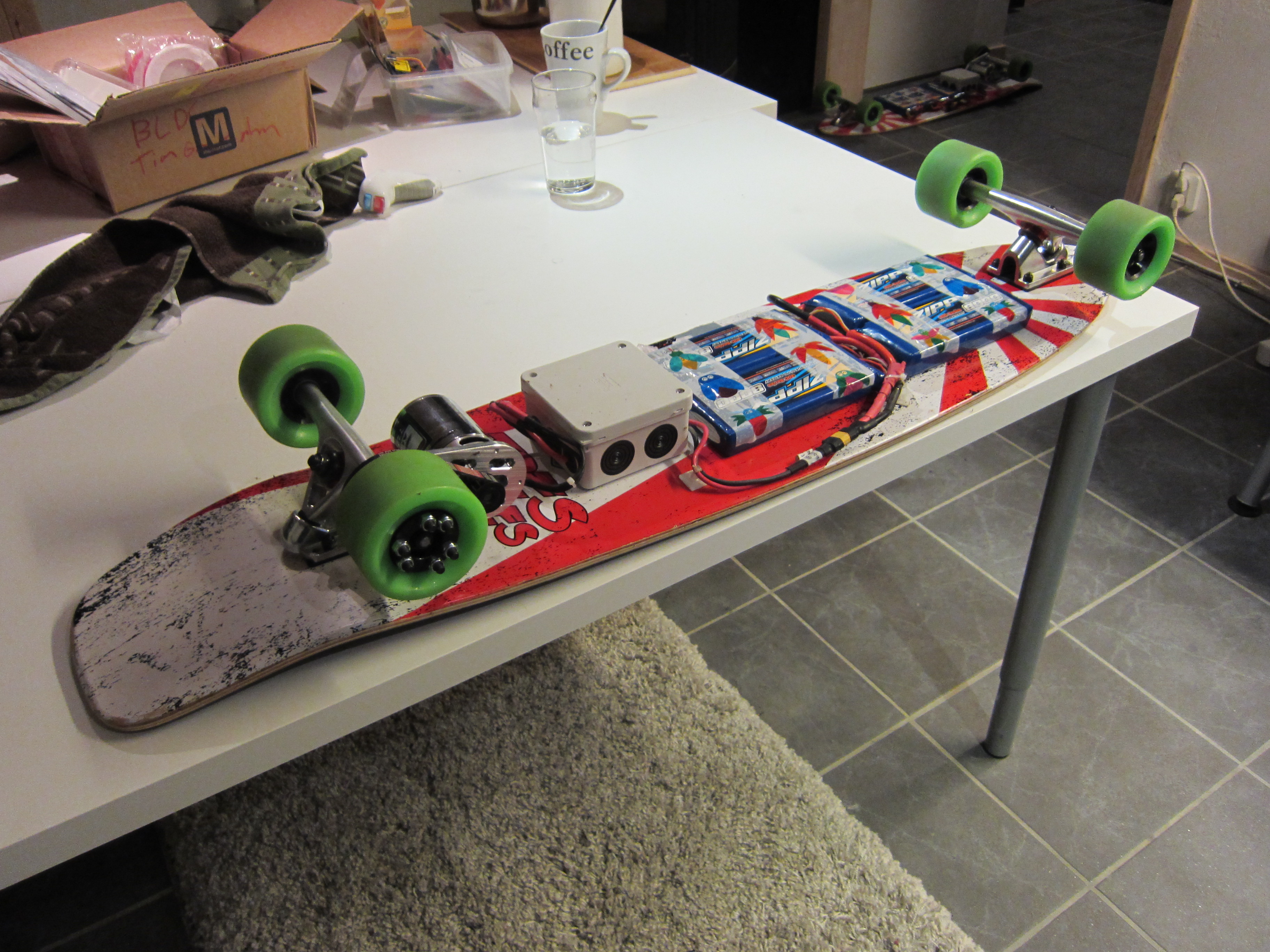
This longboard is driven by a BLDC-motor, that is controlled by a VESC (Vedder’s Electronic Speed Control). The throttle and brake is controlled by a wireless Wiimote Nunchuck.
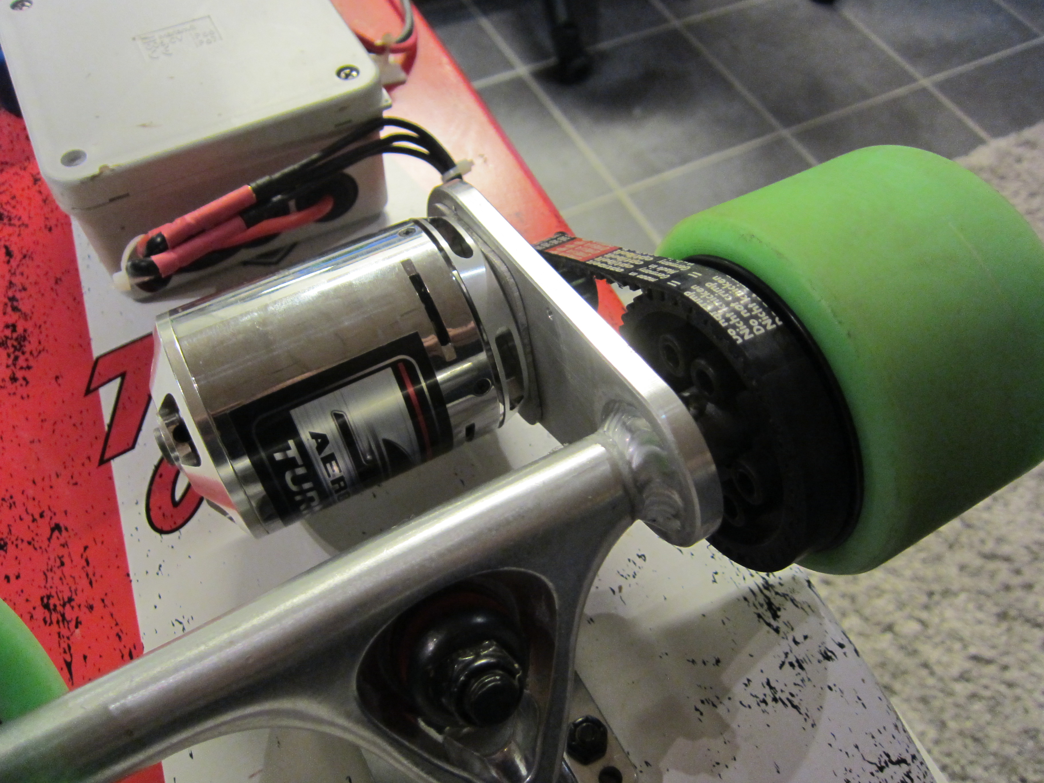
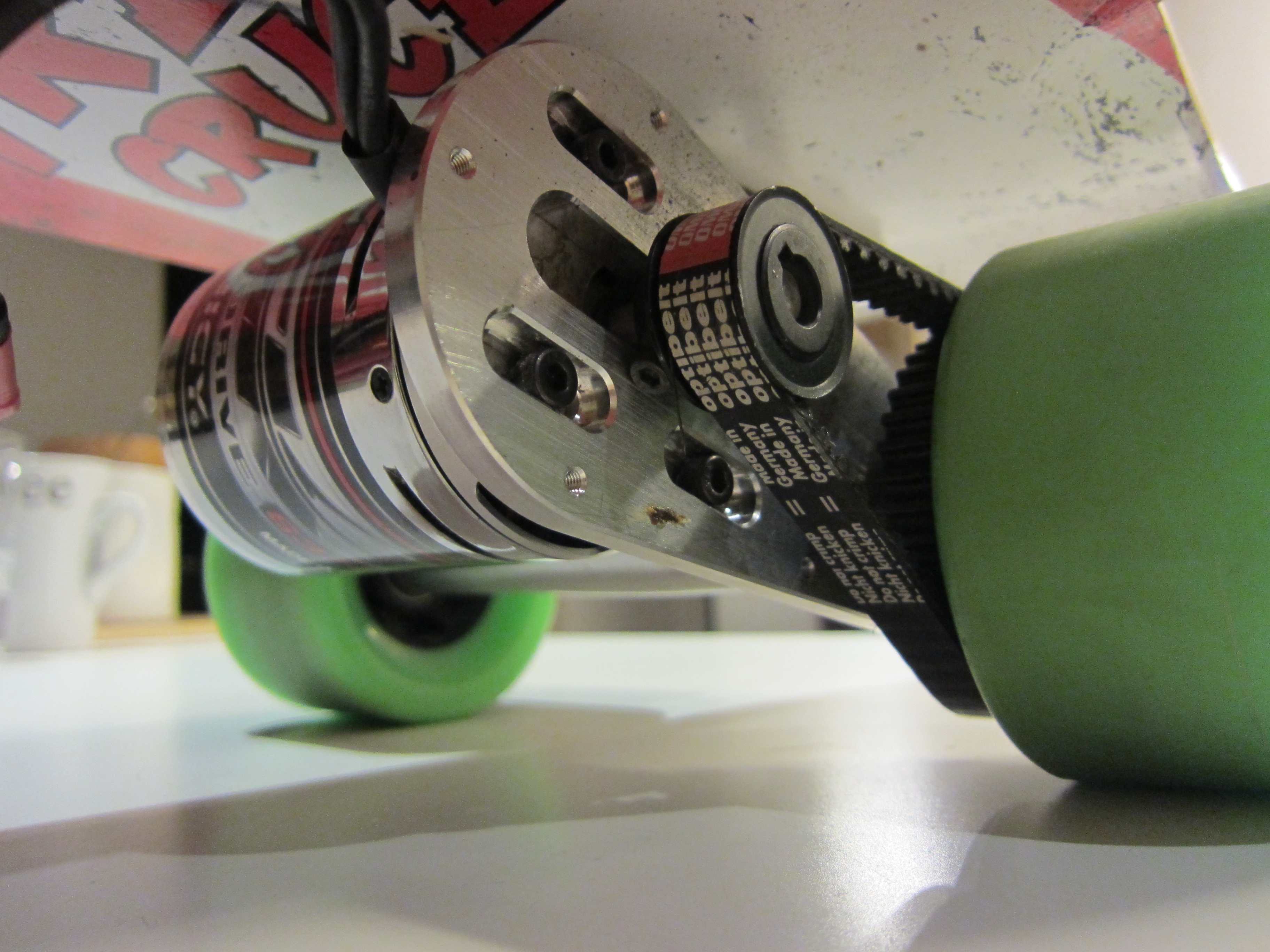
Driveline
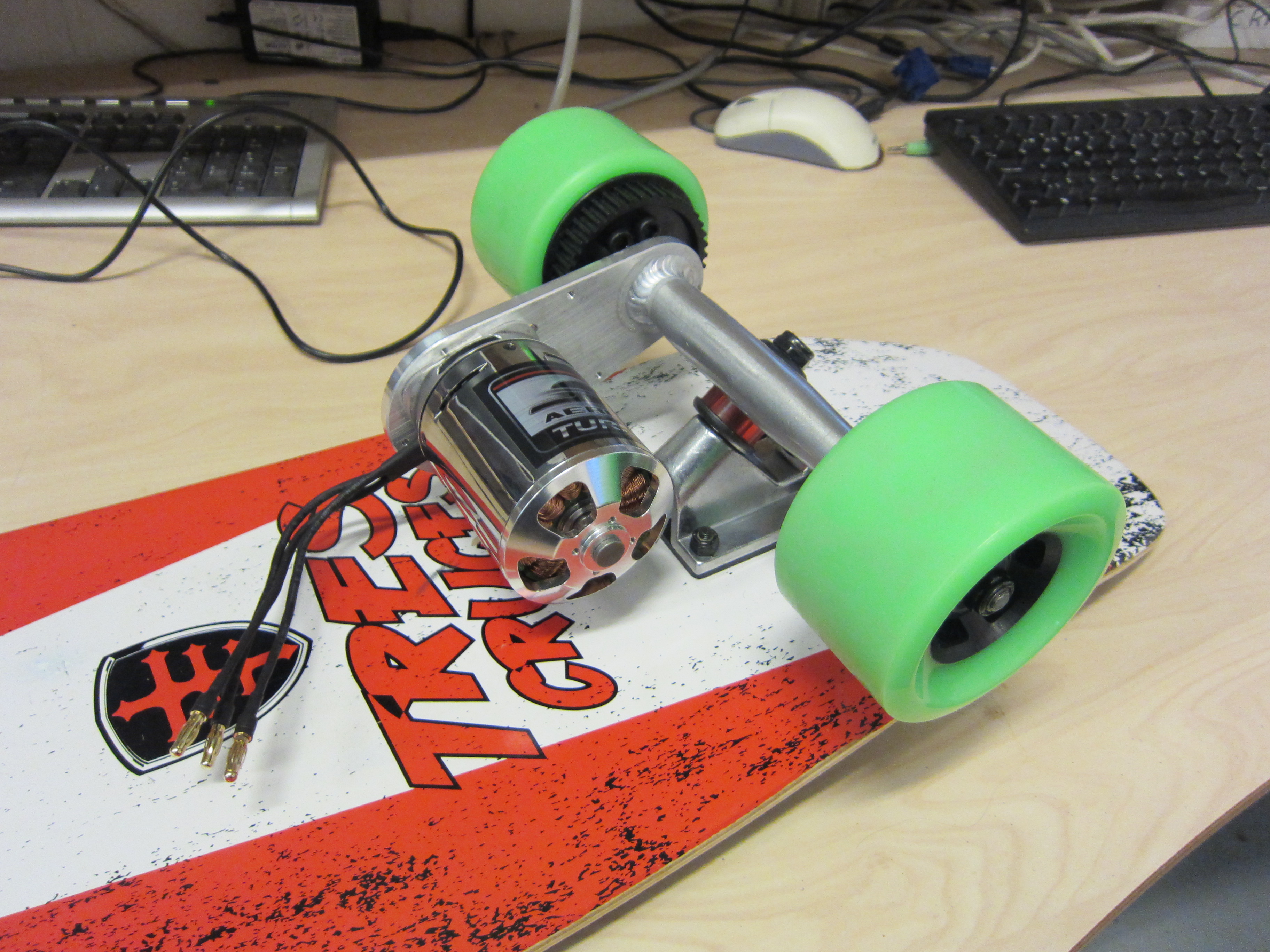


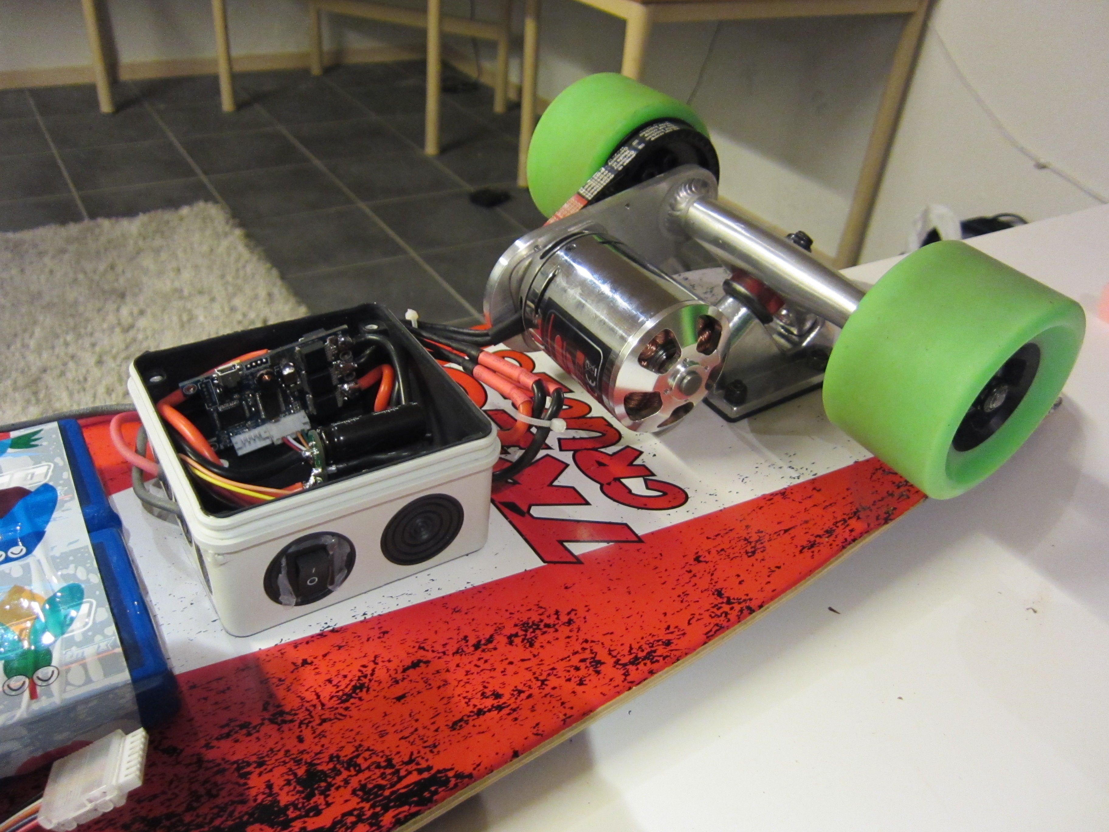
The base of the driveline is a kit by DIY Electric Skateboard (http://diyelectricskateboard.com/product/single-motor-electric-longboard-kit/).
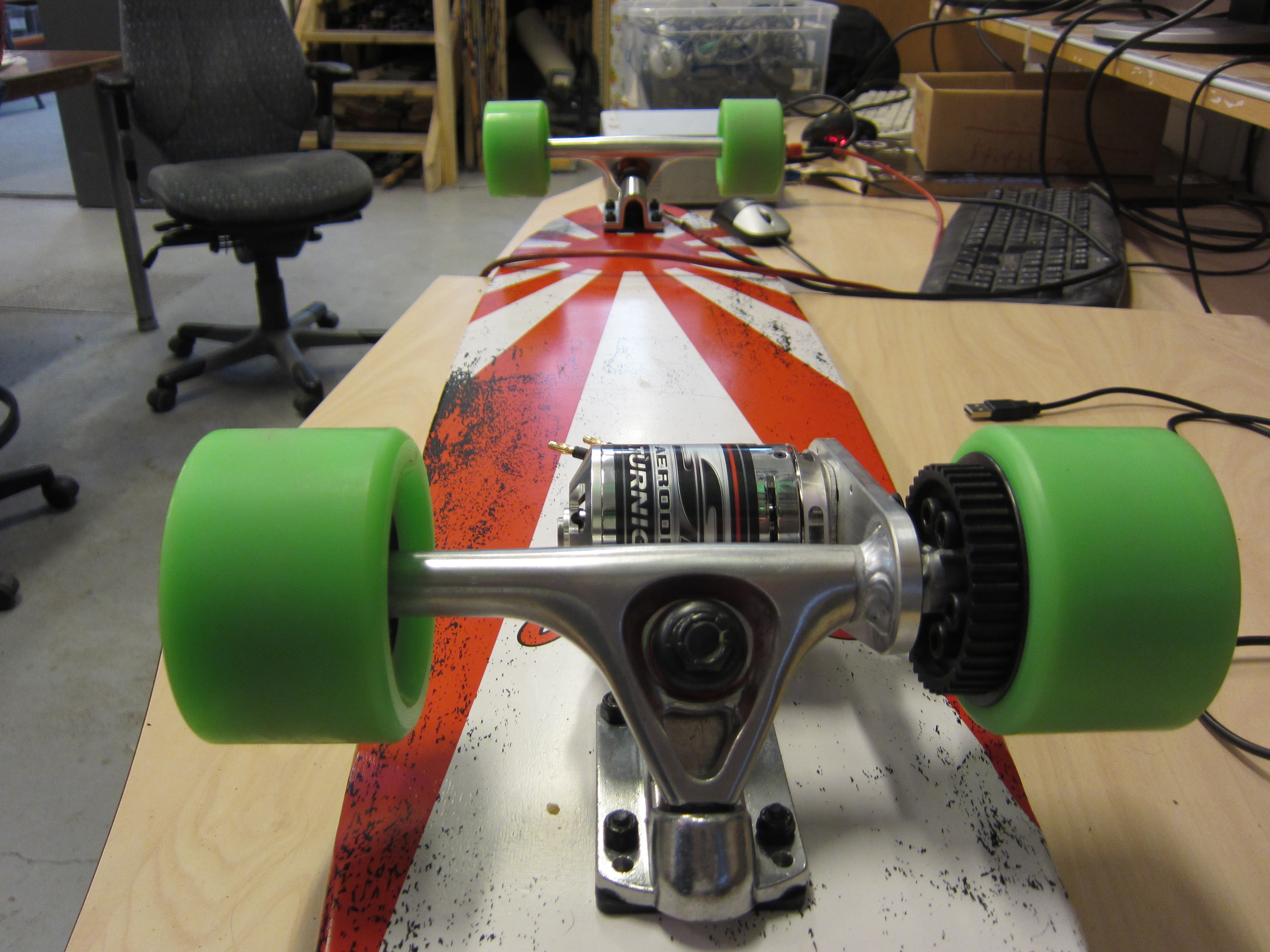
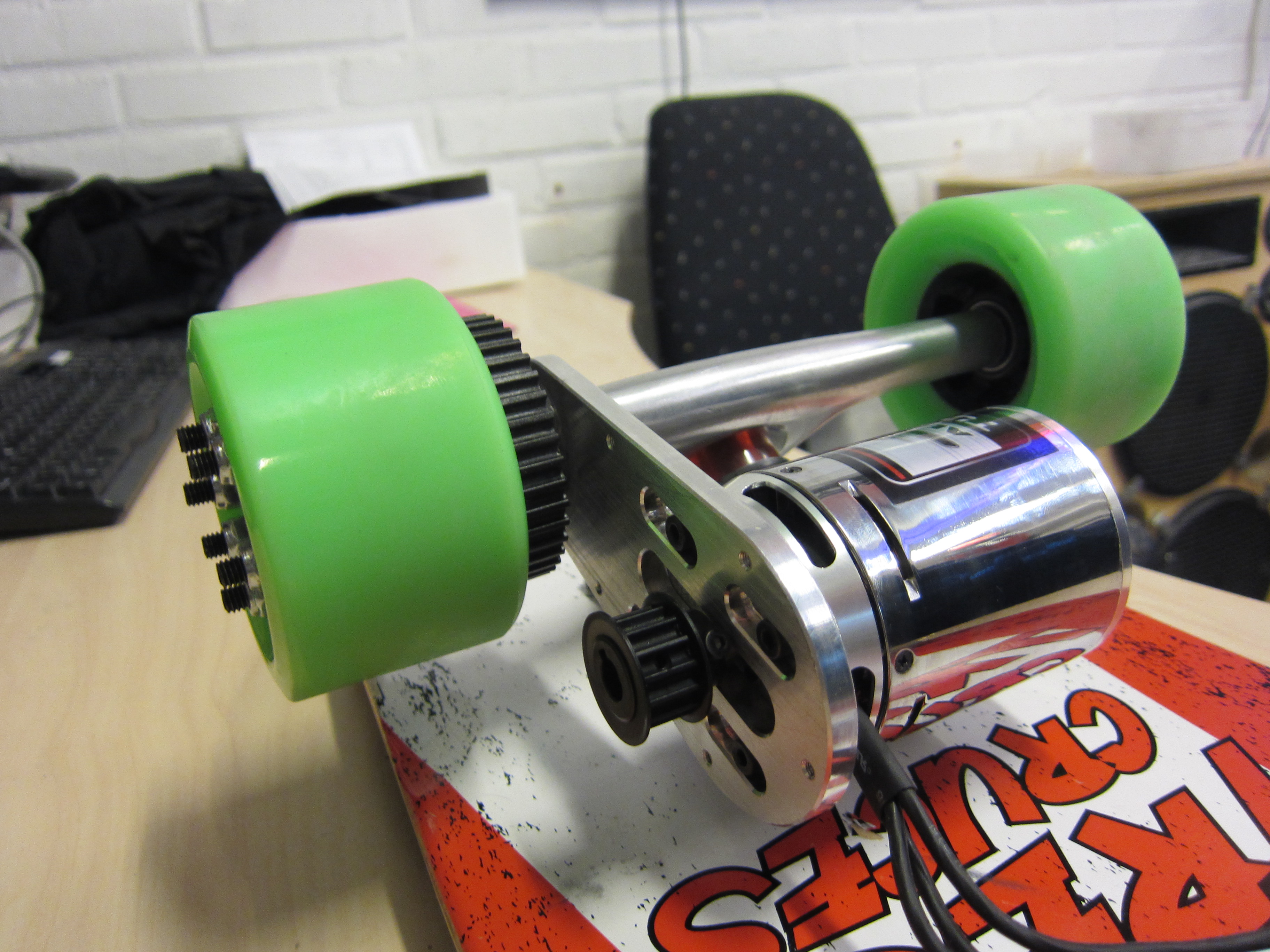
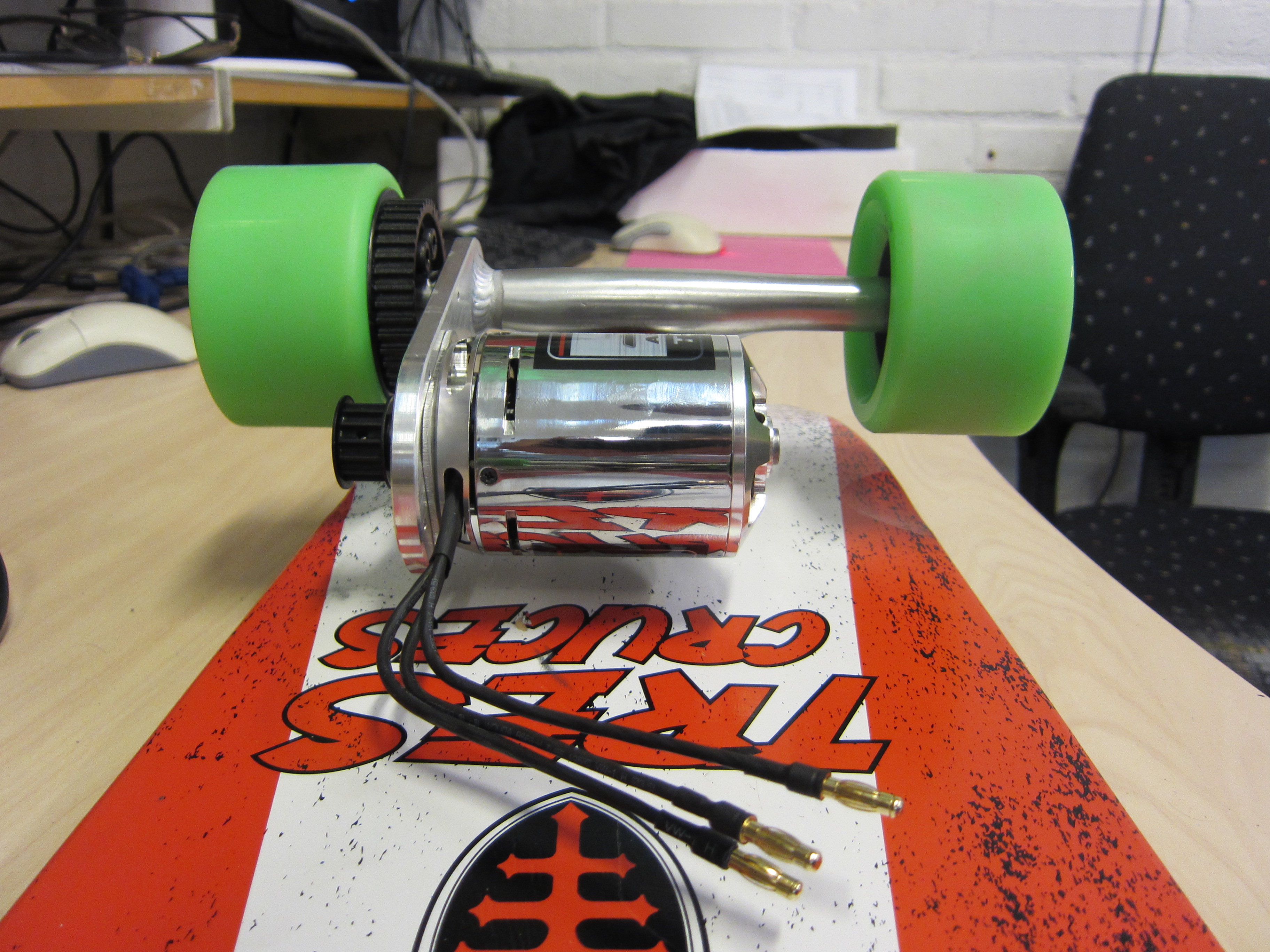
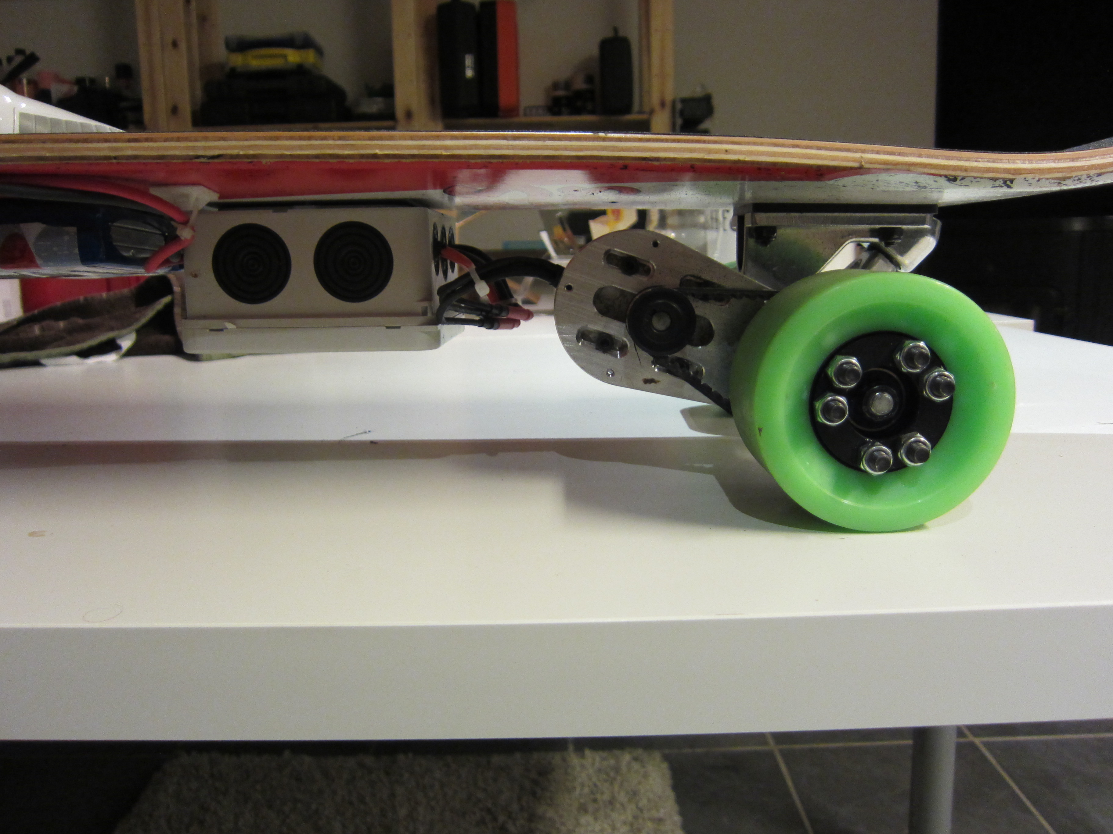
The kit is made for the SK3 motor series and included trucks with motor mount, wheels, pulleys and timing belt.
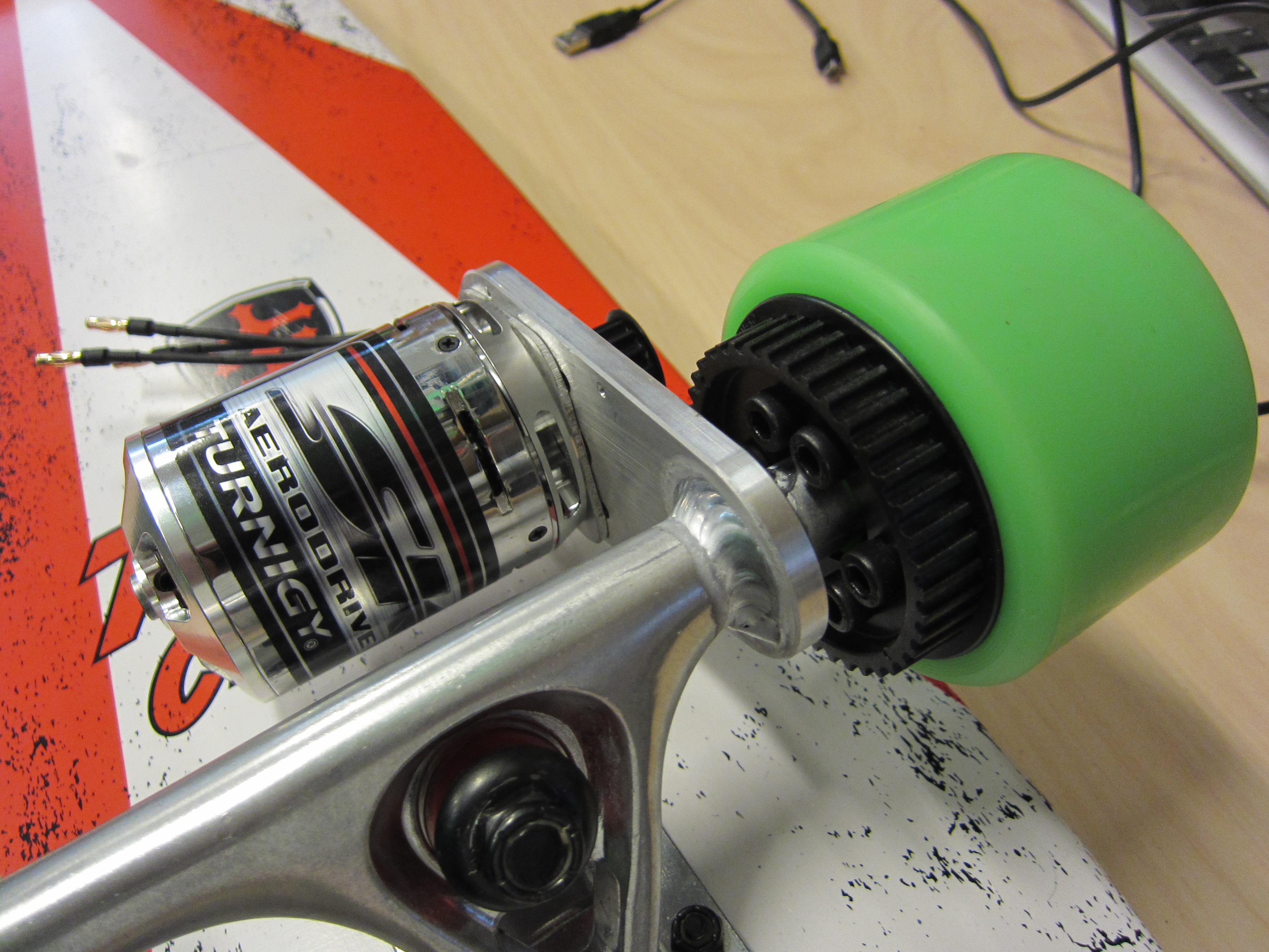
The motor mount is welded into the truck, the design is really good and the welding job is well done. The drive pulley is the weak point in the drive line, it’s wobbly and hard to calibrate. DIY Electric Skateboard seems to have switched it for a new pulley made out of aluminum now.
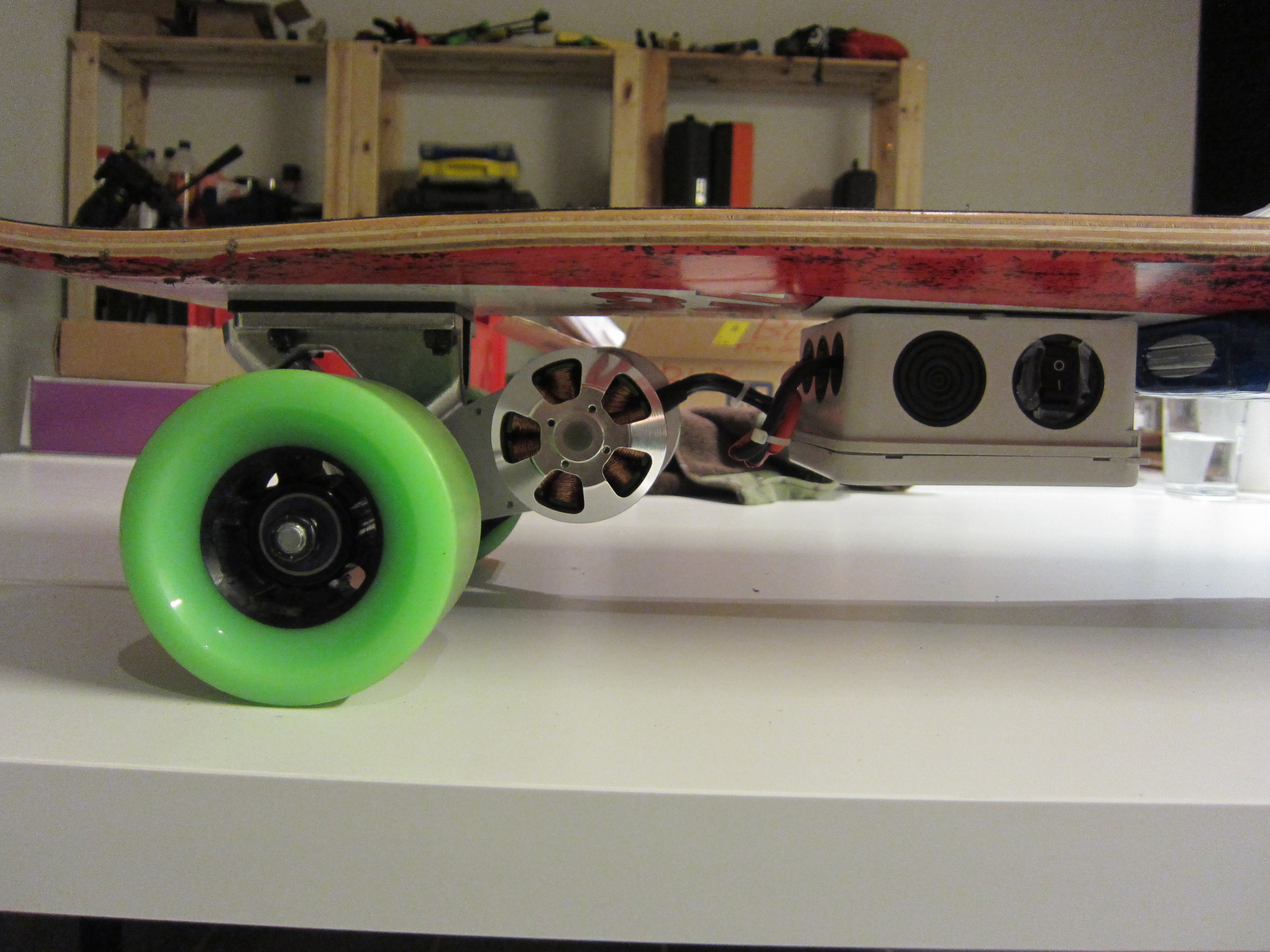
The motor is a Turnigy Aerodrive SK3 168kv 2400W Brushless Outrunner Motor (http://hobbyking.com/hobbyking/store/uh_viewItem.asp?idProduct=38055).
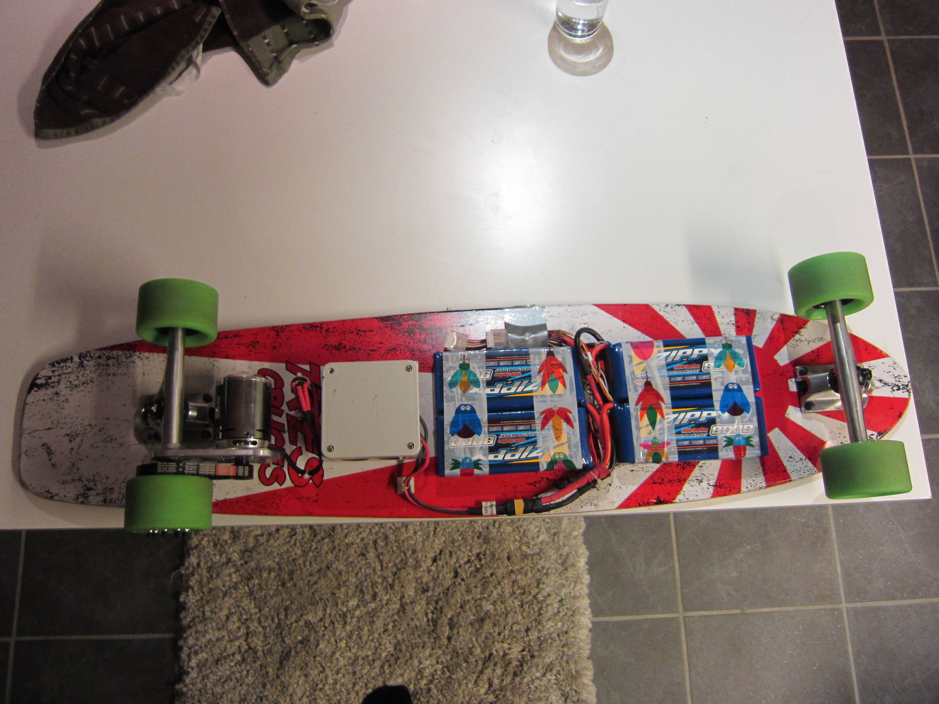
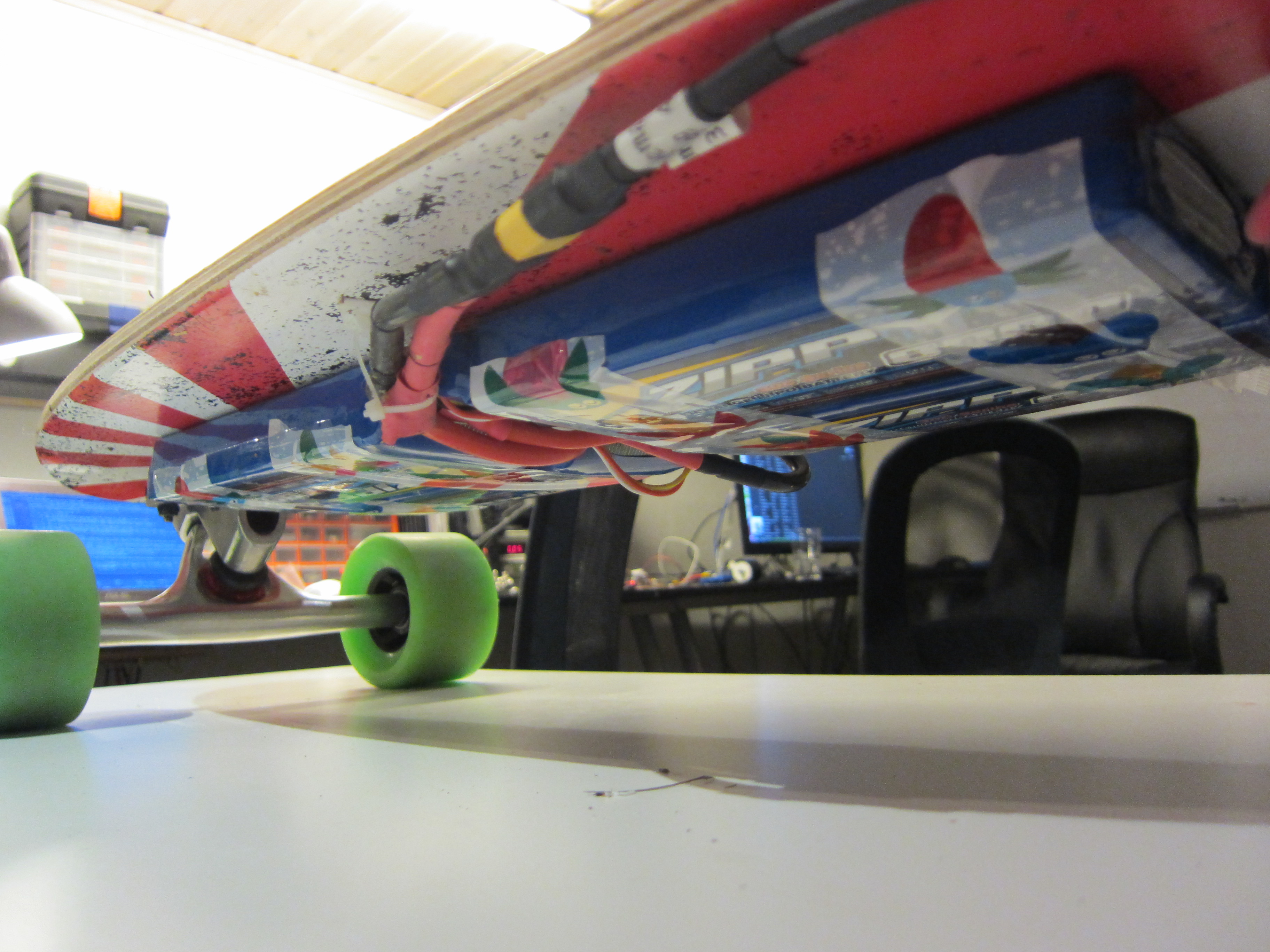
Battery
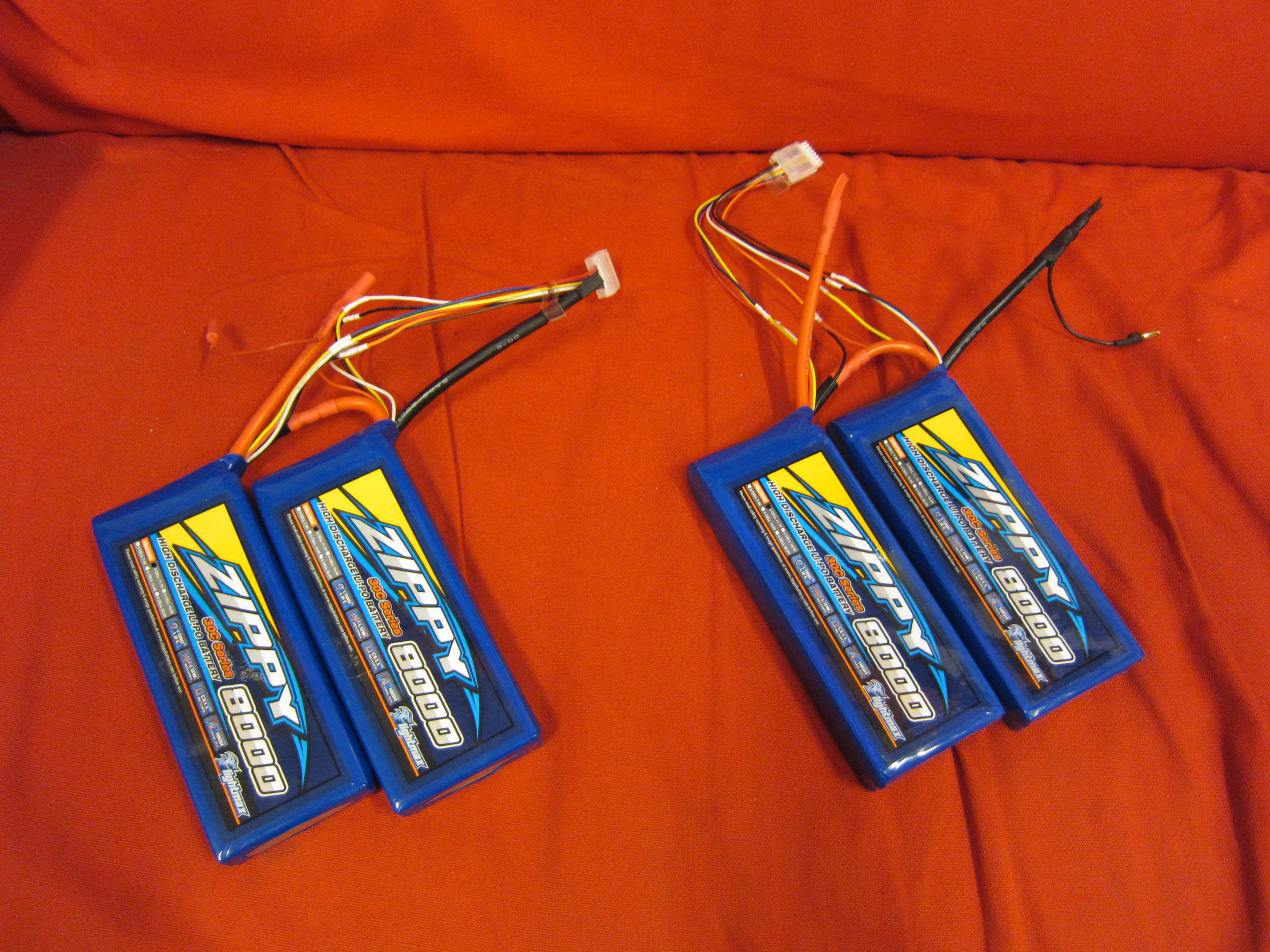
On the board I use 4x3s LiPo 8Ah 30C (http://hobbyking.com/hobbyking/store/uh_viewItem.asp?idProduct=32214), it gives about 350 Watt hours of energy.
VESC
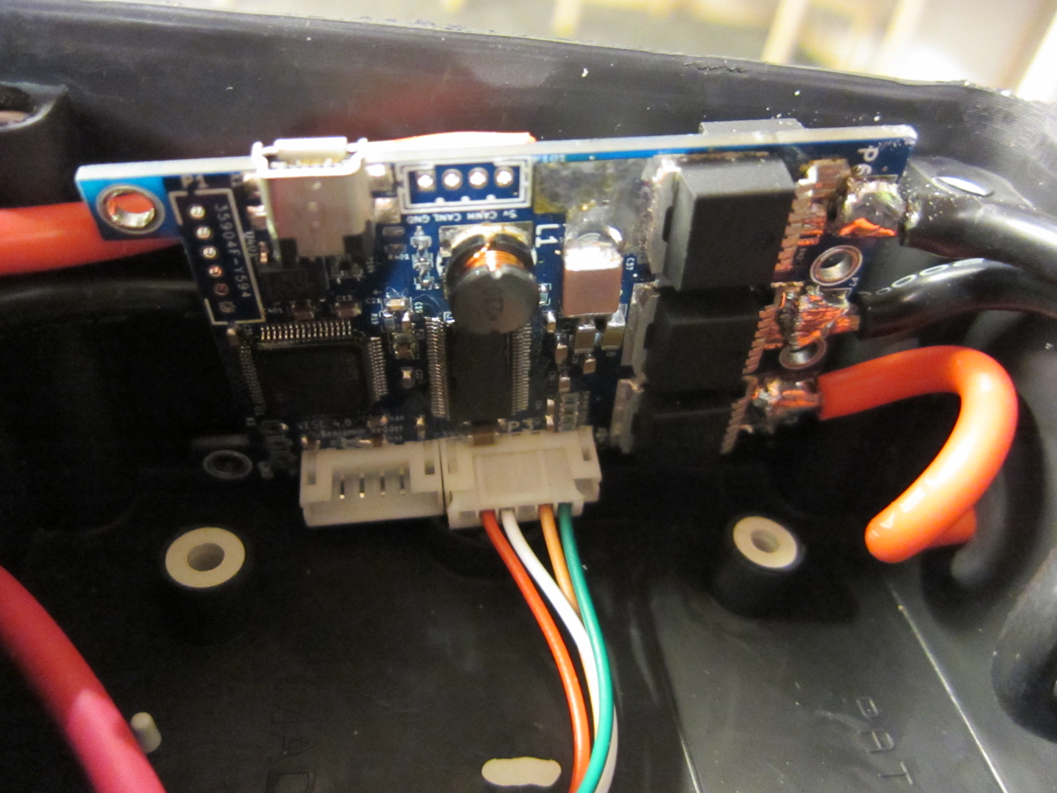
The motor driver is developed by Benjamin Vedder, he have been developing several years now and he have been implementing a lot of nice features into the ESC.
The VESC can drive a brushless motor sensorless, it measures the back-EMF and can track the position very accurate even at low RPM’s. It also has regenerative braking that charges the battery’s while braking.
A nice feature is also the cruise control, it’s PID regulated and very accurate because of the good tracking of the motors position.
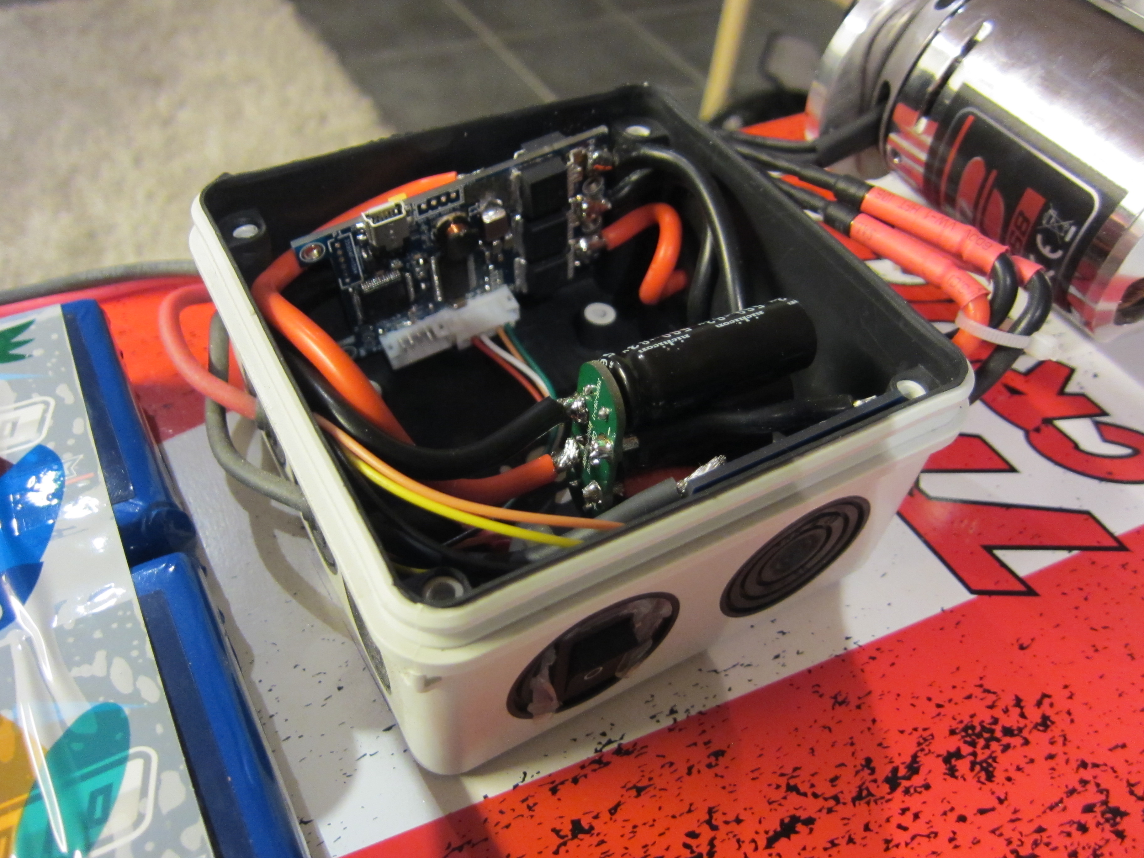
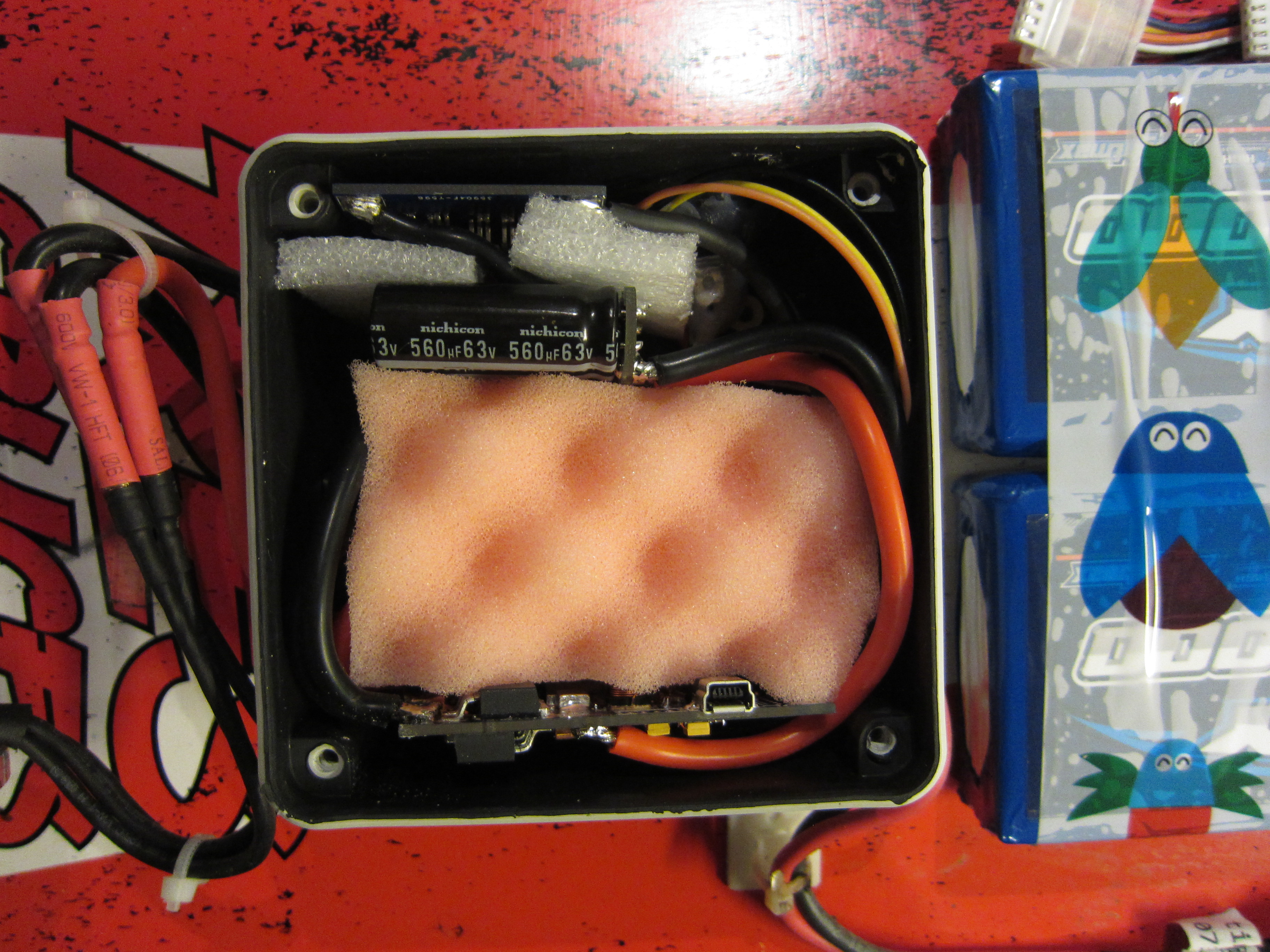
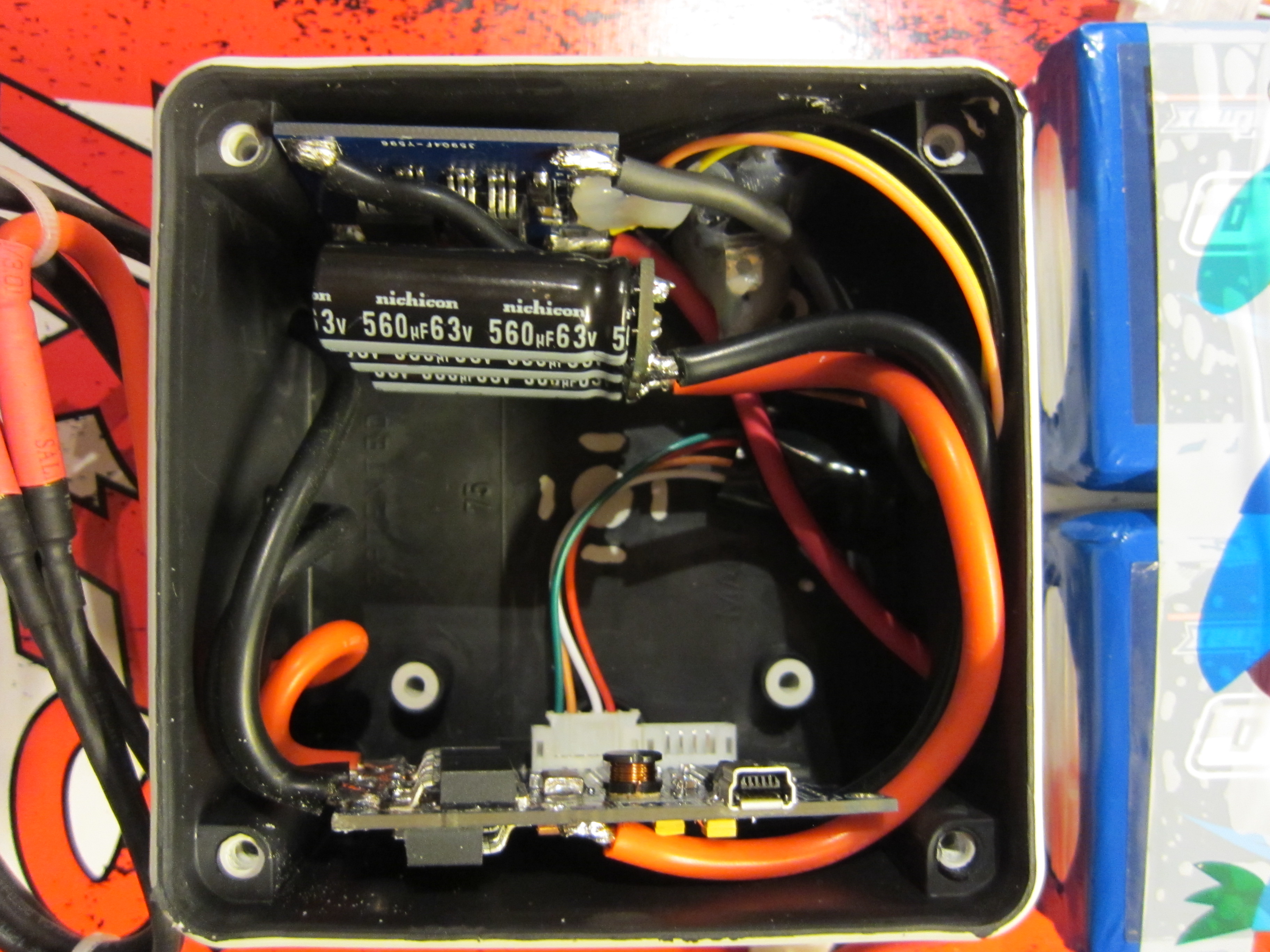
I used a nice IP67 rated rubber sealed case for the VESC (http://www.biltema.se/sv/Bygg/El/Fast-installation/Kopplingsdosa-2000021071/).
A big capacitor us coupled together with the VESC, it creates a big inrush current when the battery is plugged in. A big inrush current can create sparks that oxidizes the connectors and make big ripples in the voltage in to the VESC that can cause damages. Vedder made a small PCB that slowly charges the capacitor, it’s based on a charging schematic from the forum Endless Sphere.
The capacitors and the inrush limiter is hosted in the casing as well.
Wiimote nunchuck
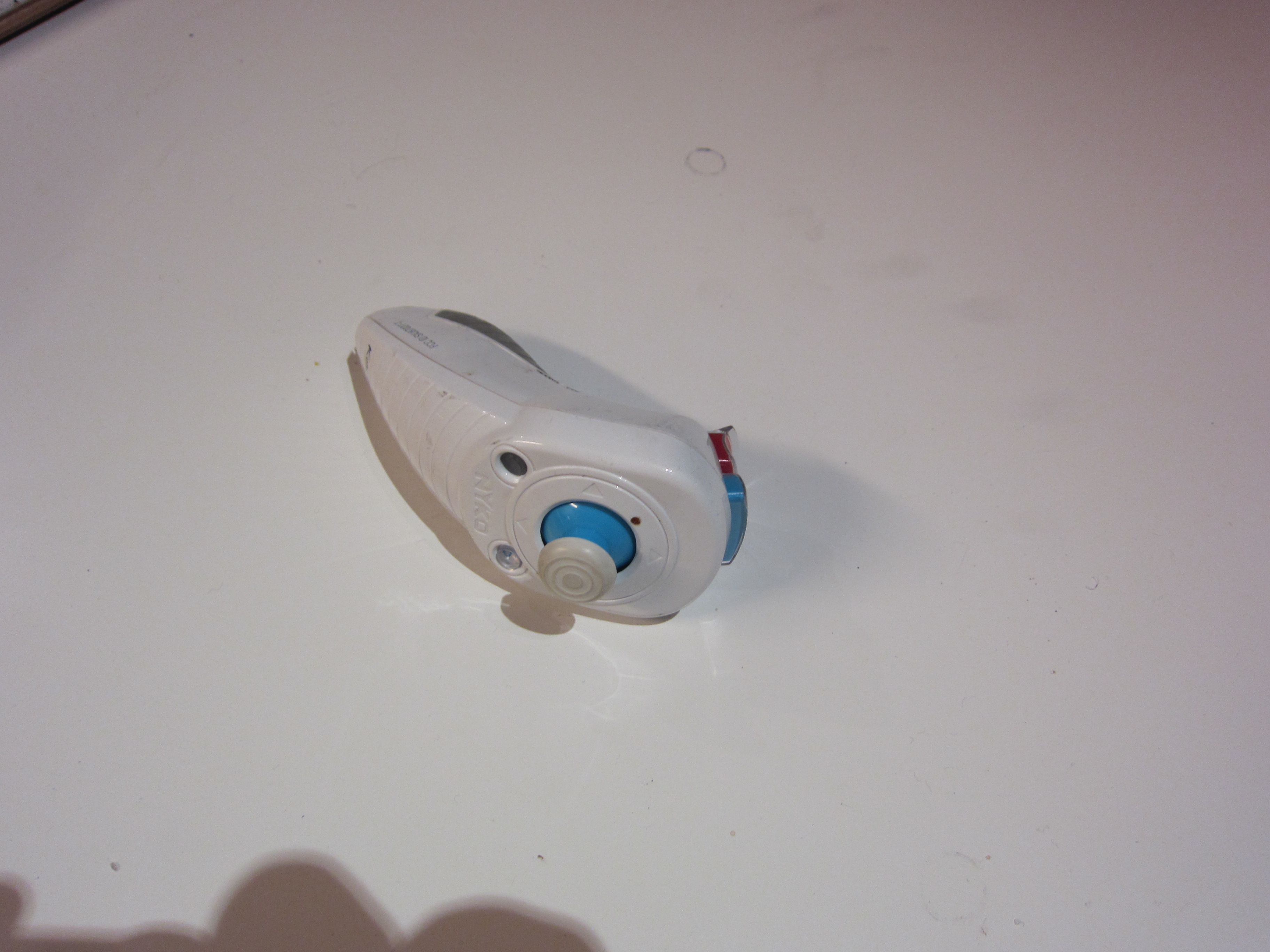
The Nunchuck for Wiimote has a nice grip and several extra buttons to use for extra functions. Nyko does make a wireless version of the Wiimote Nunchuck.
The Nunchuck is communicating with the Wiimote through I2C, so is the wireless receiver for the wireless version of the Nunchuck. The wireless receiver is stripped of its case and hooked in to a I2C bus on the VESC.
Because the Nuncuck is made for gaming it keeps sending the last known command on connection loss, for example so that the gamers gas pedal won’t be affected in game. This is not a good thing when you are driving for real.
Vedder has made a replacement PCB for the Nunchuck chassis that using the NRF24L01+ radio. It’s more safer and have a greater sending distance.
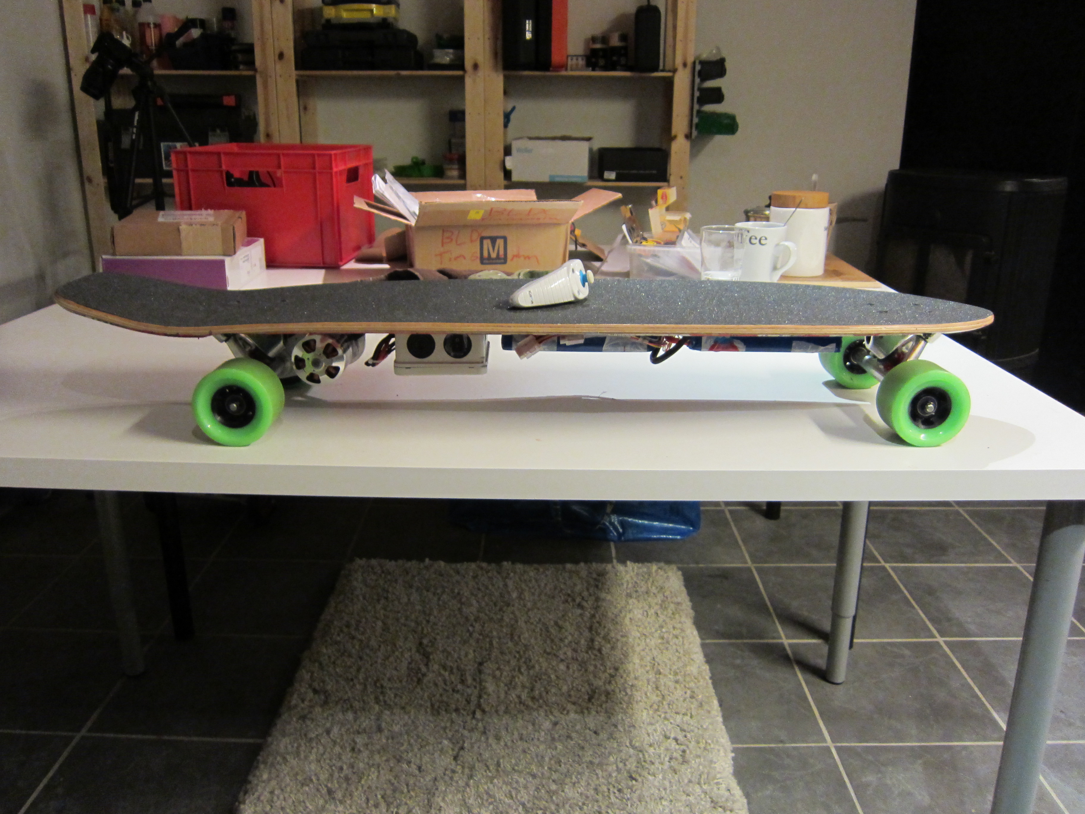
The longboard
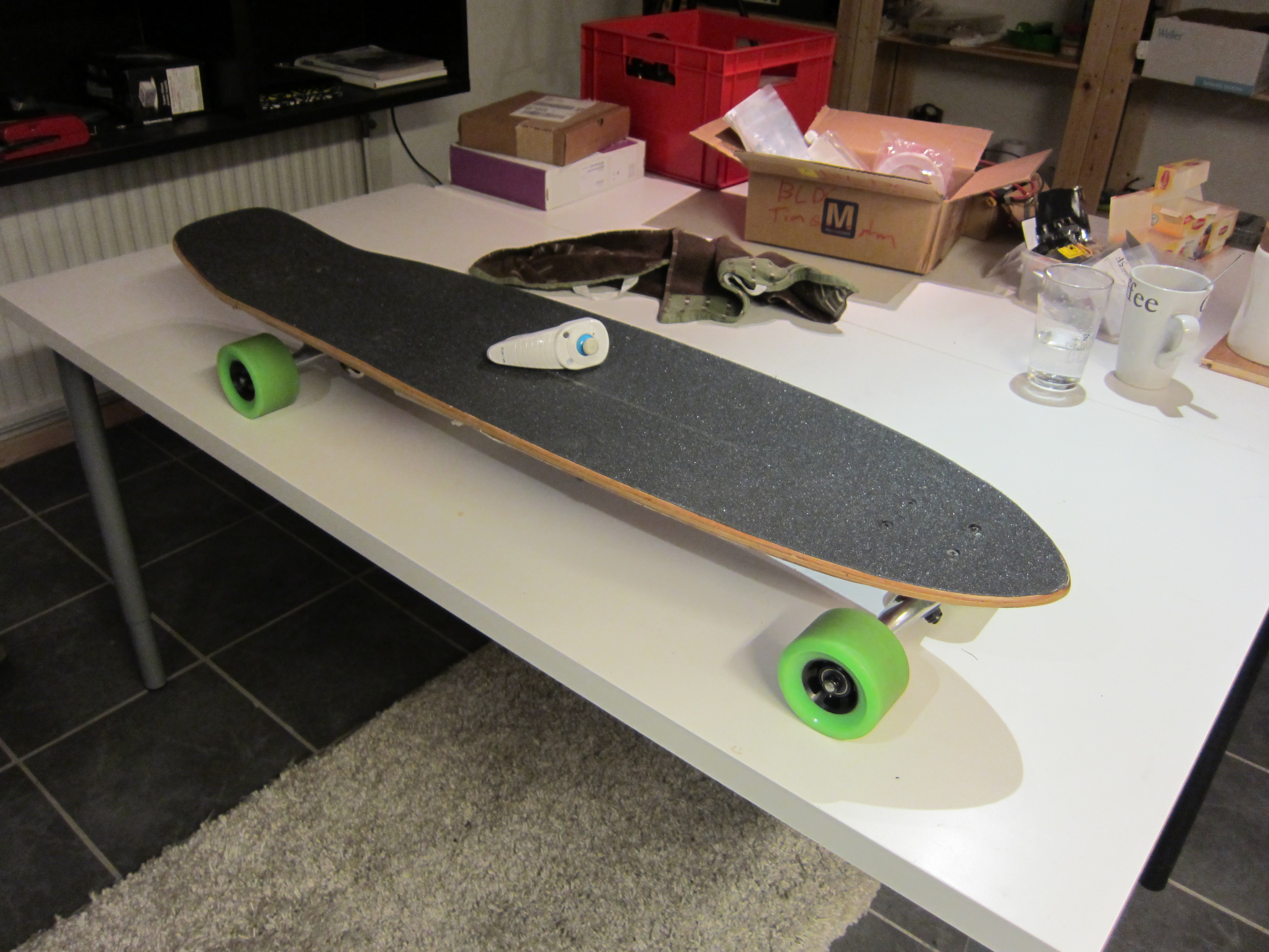

Driving experience
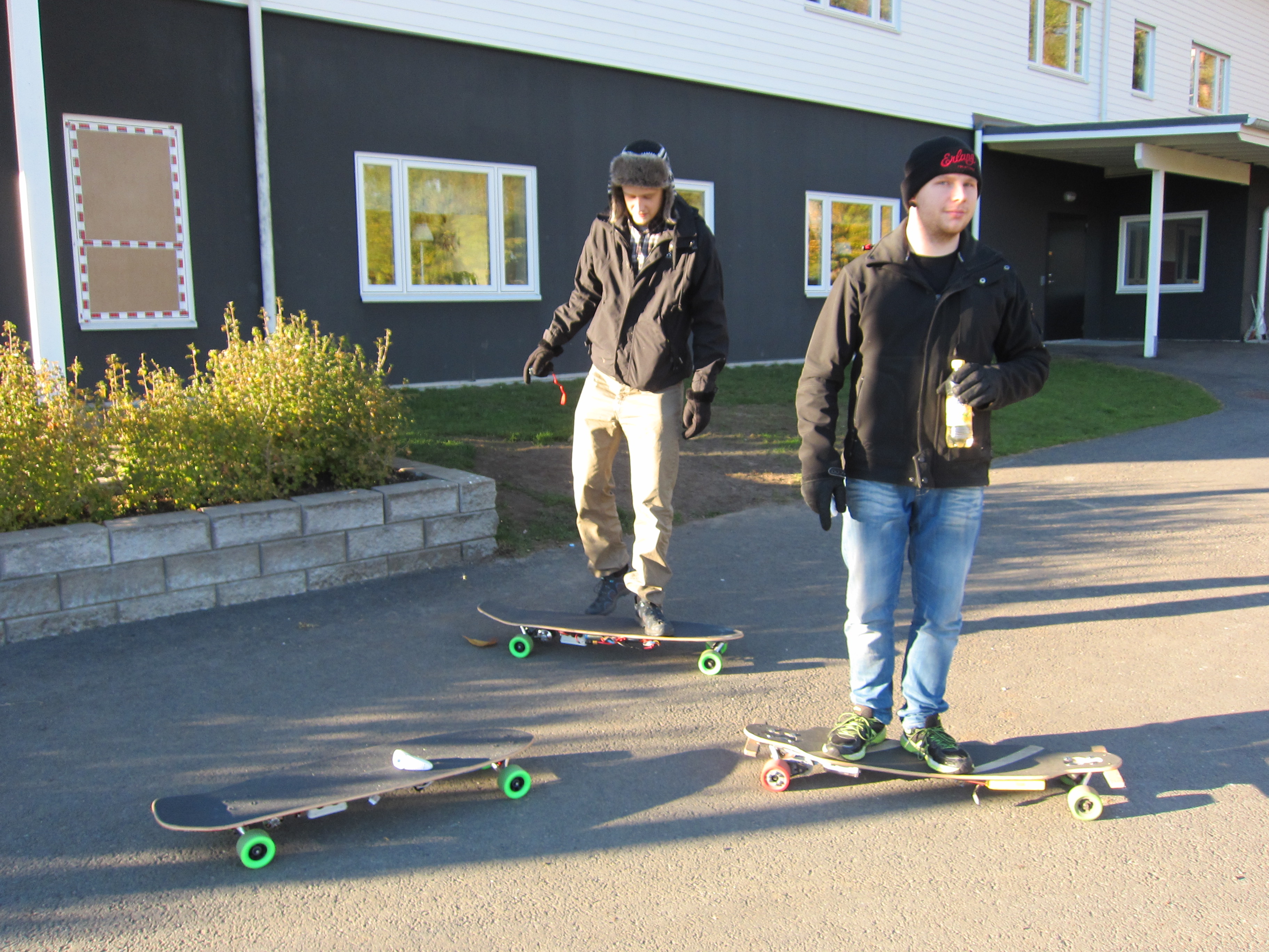
Although I have no longboarding or skateboard experience i found it quite easy to ride the electric longboard. I found it easier to keep my balance on the board while having constant power driving it forward. The ability to brake also makes it easier to get on and off.
It’s a really fun way of transportation, it’s fast and you can carry the longboard every where when don’t driving.