
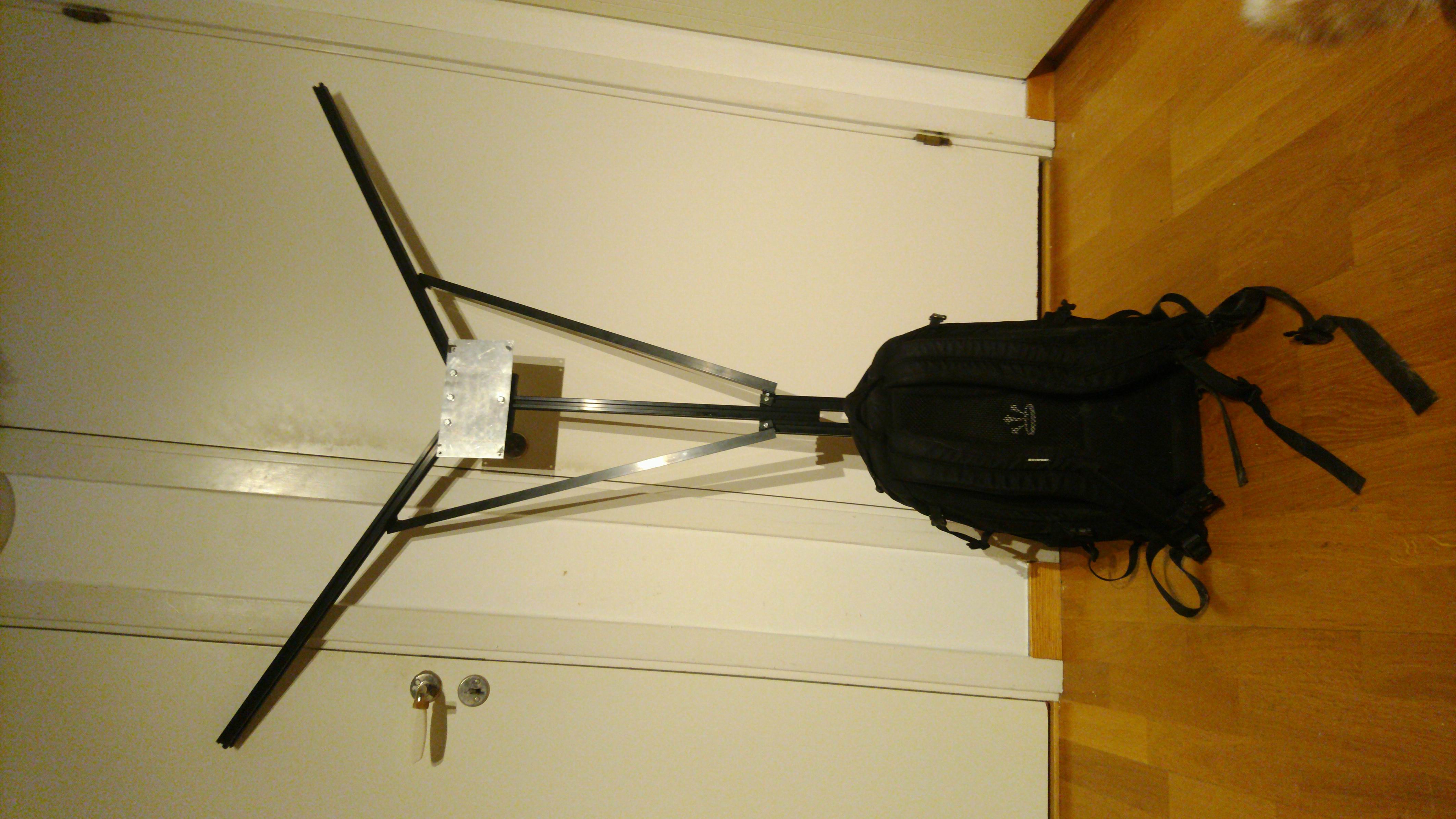
Ljusmaskinen is a portable light rig attached to a backpack. It’s made for complementing Festmaskinen.
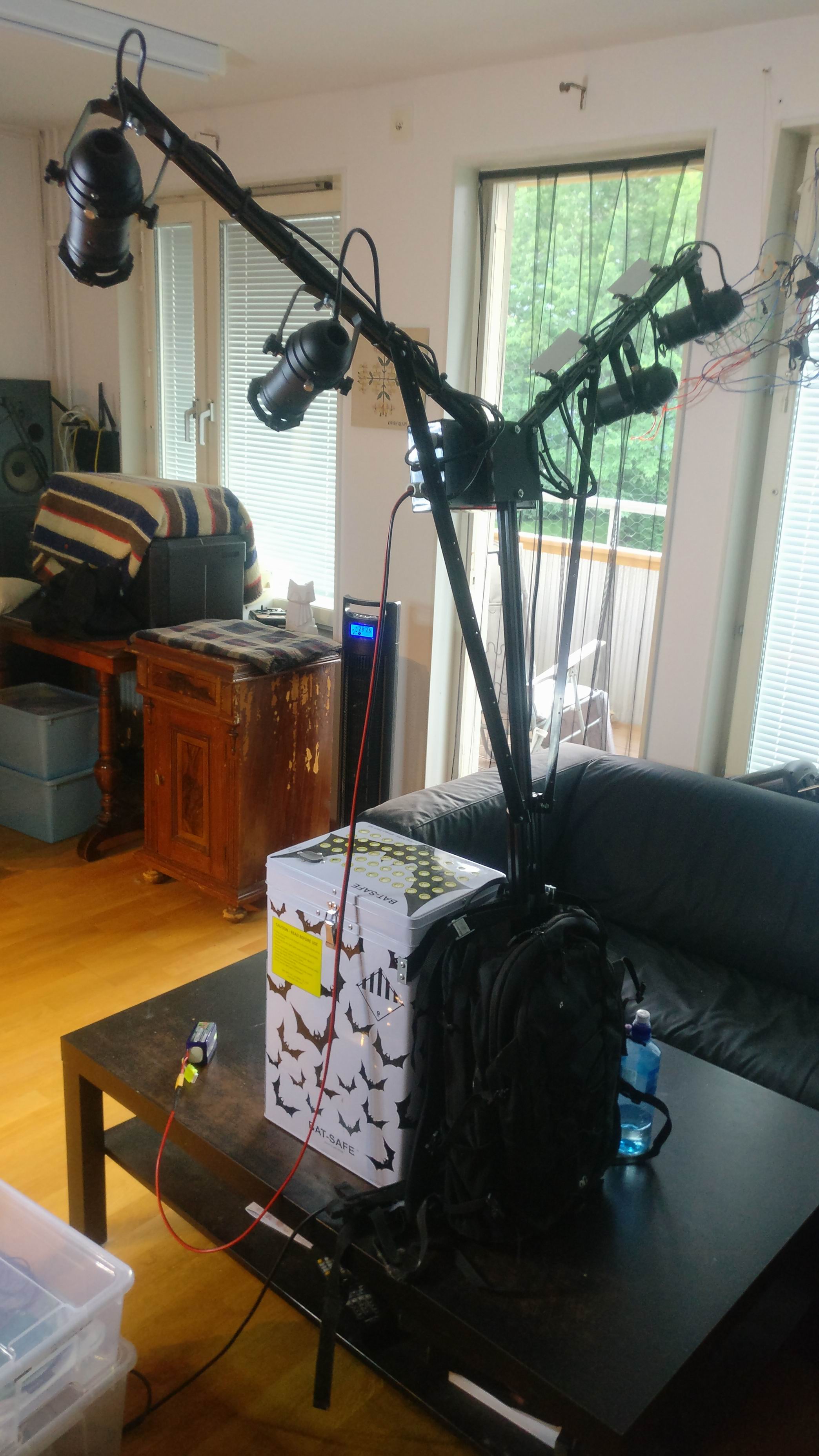

It’s got 4x4W RGBW spots and 4x10W COB LED’s mounted on a rig made out of aluminium profile.
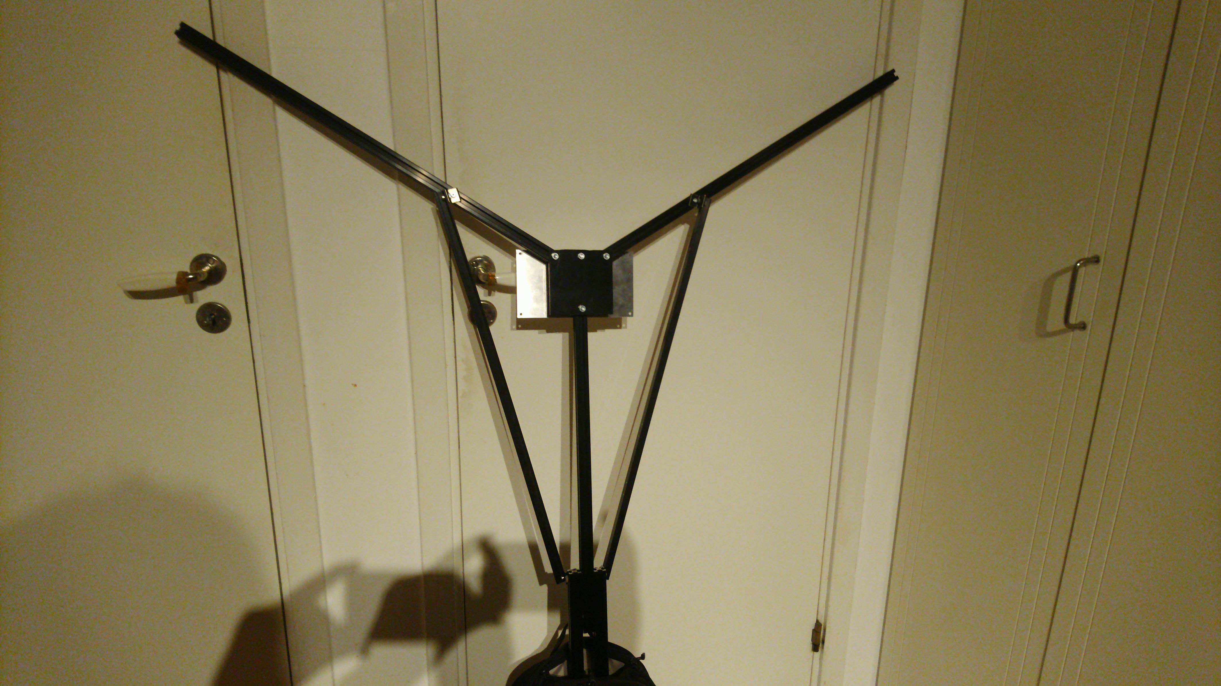
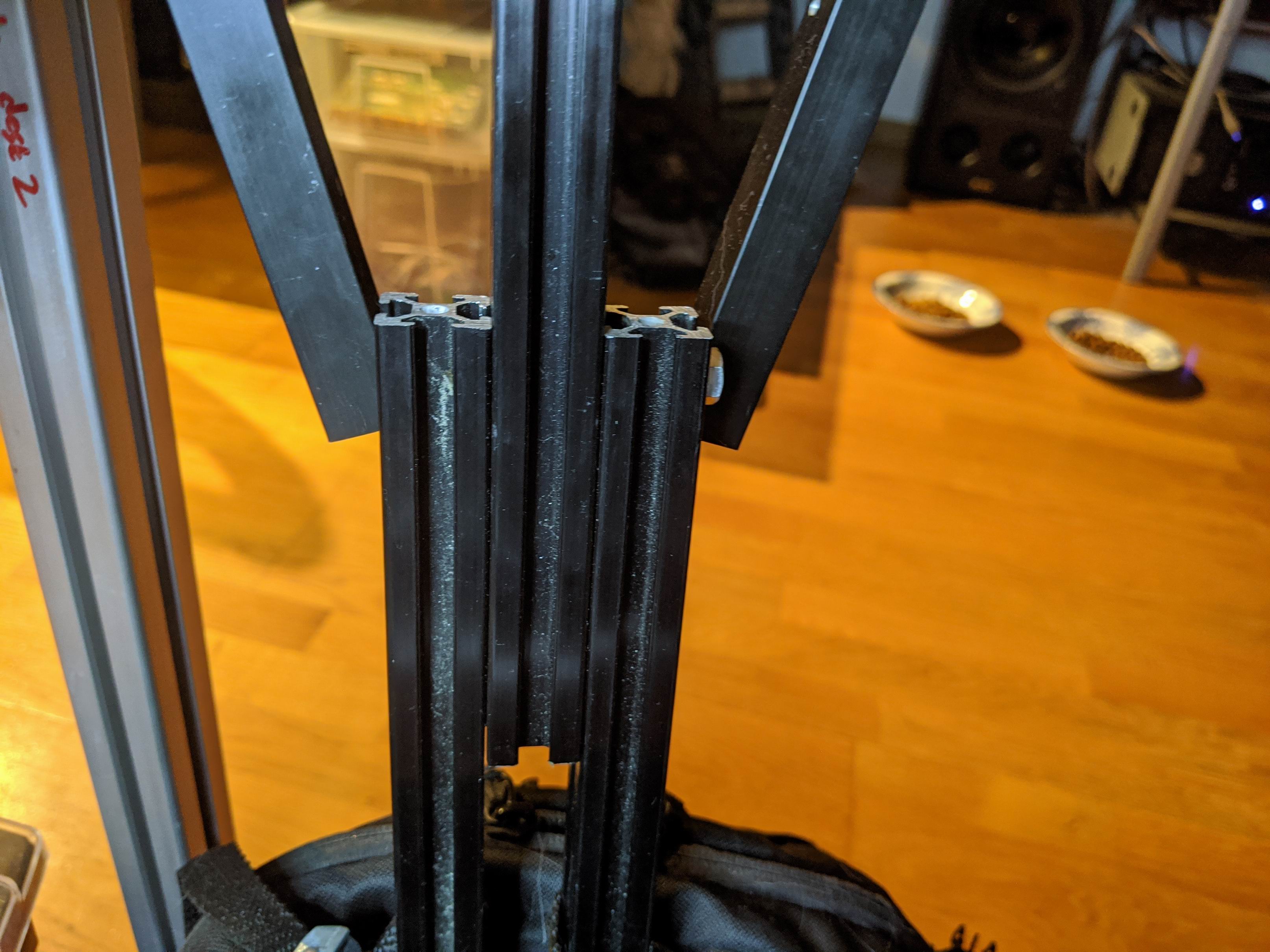
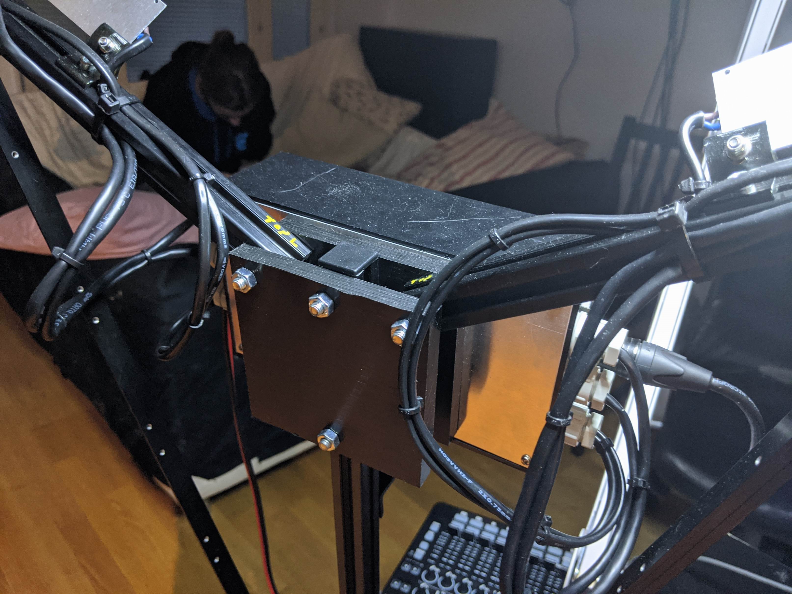
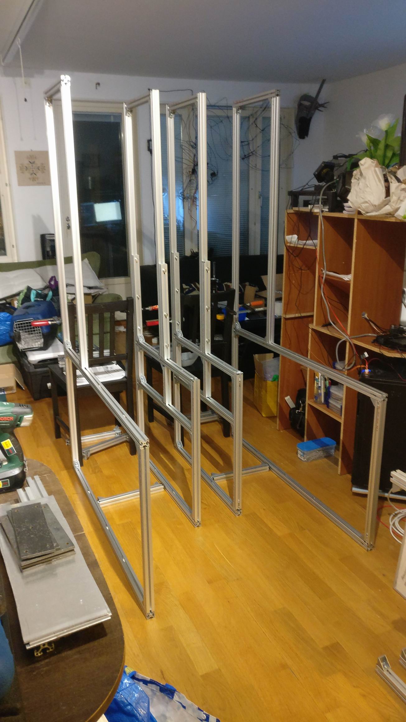
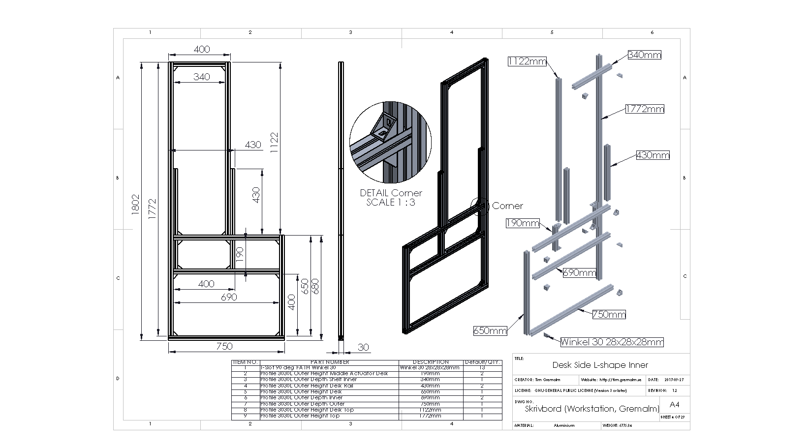
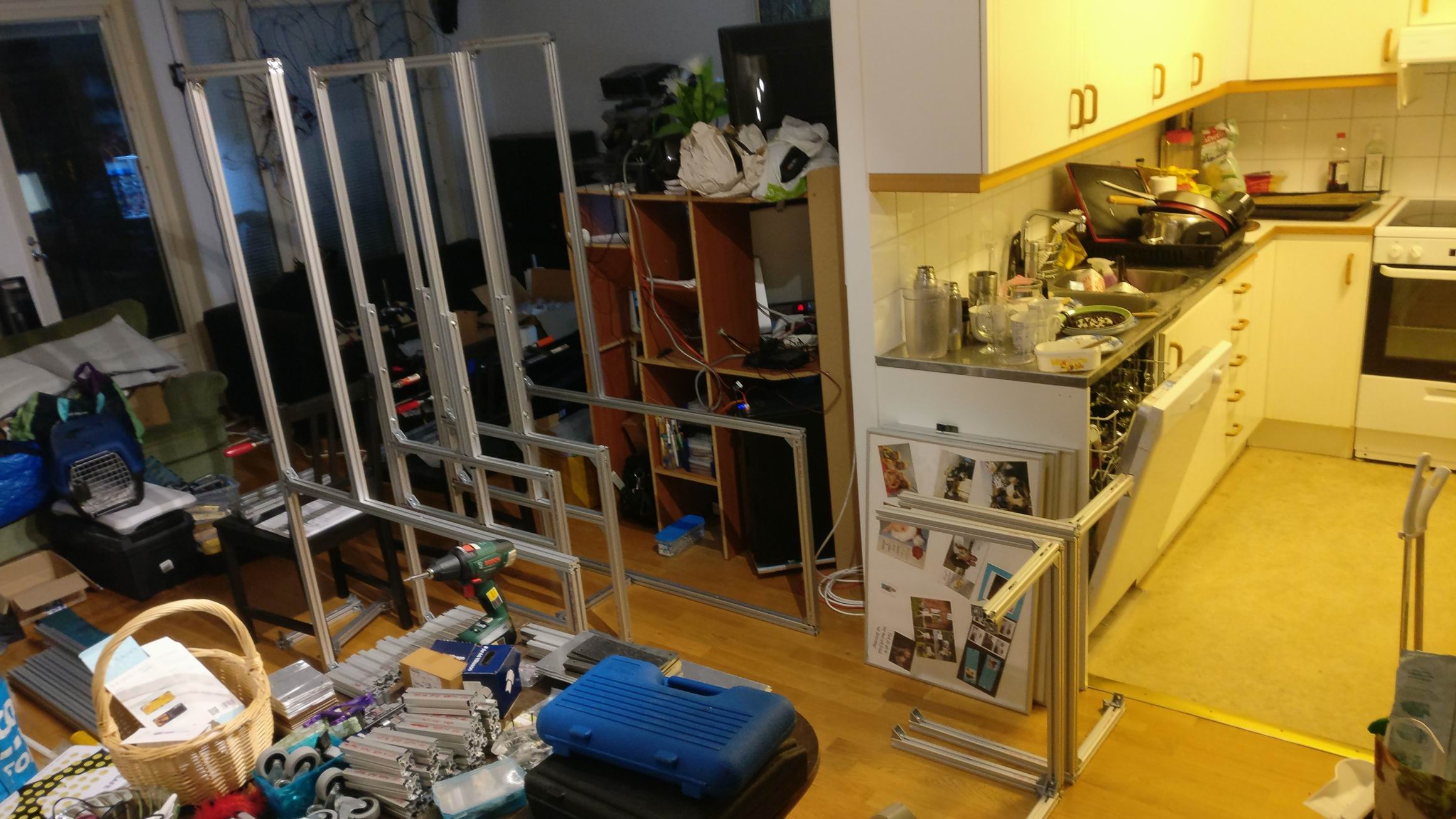
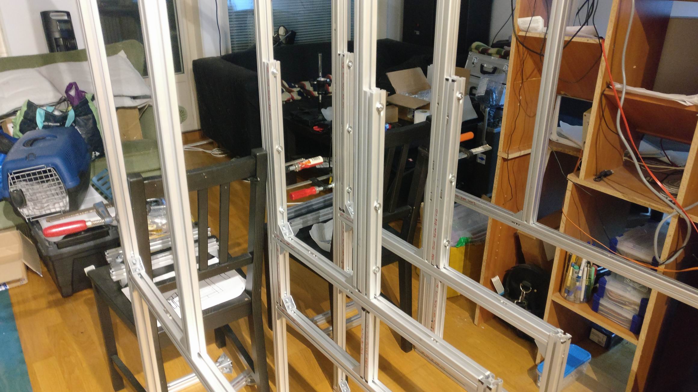
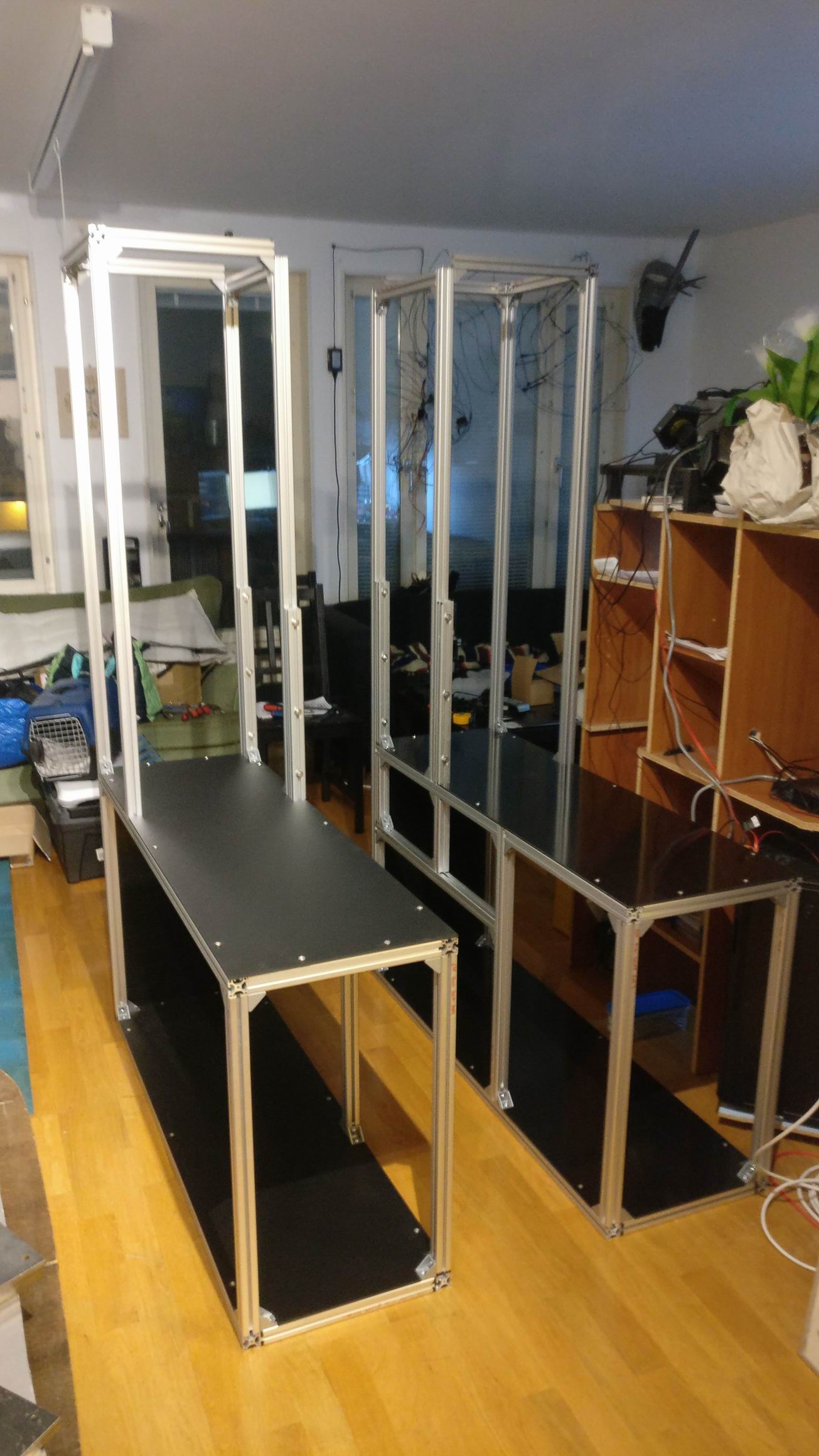
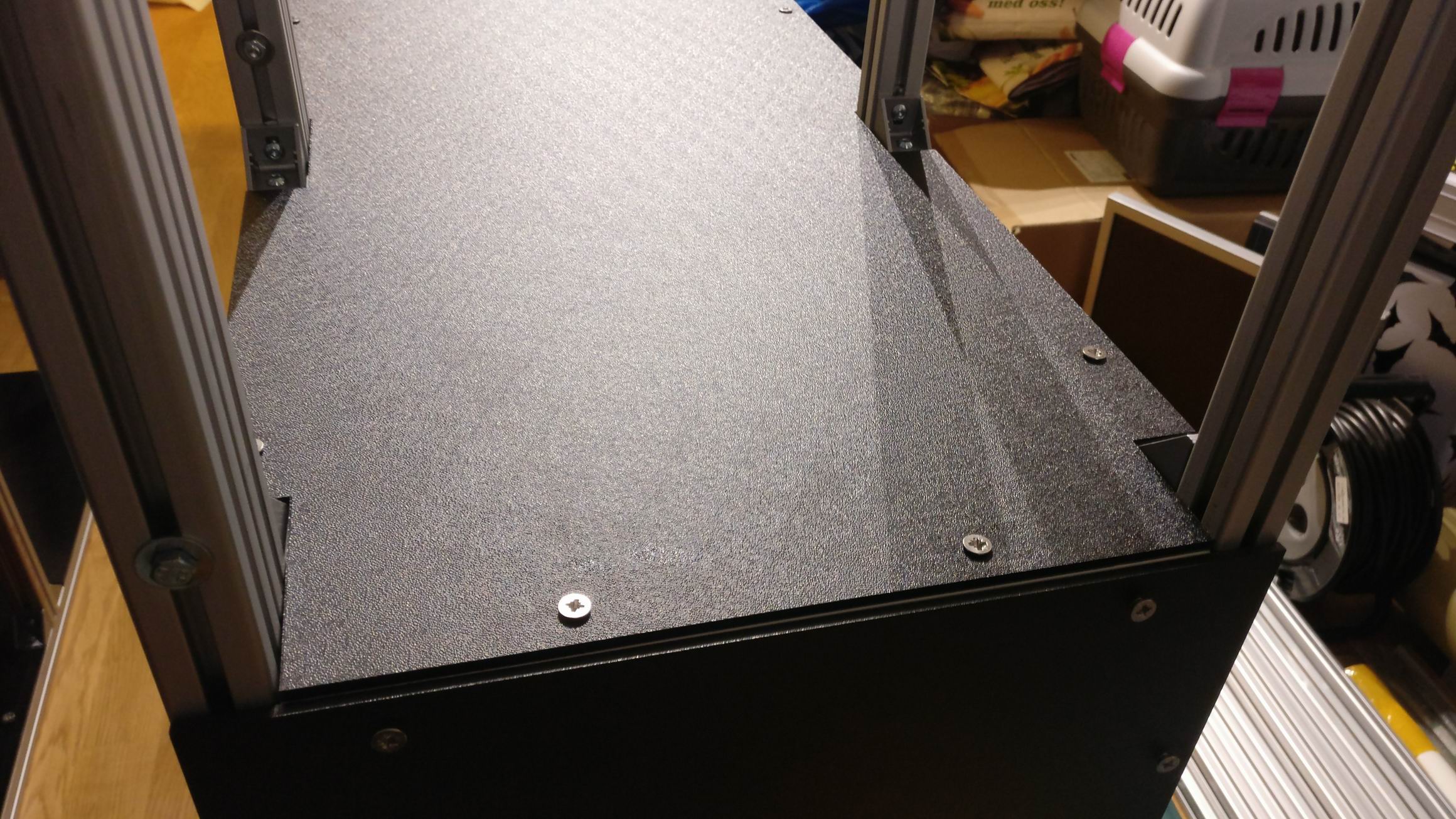
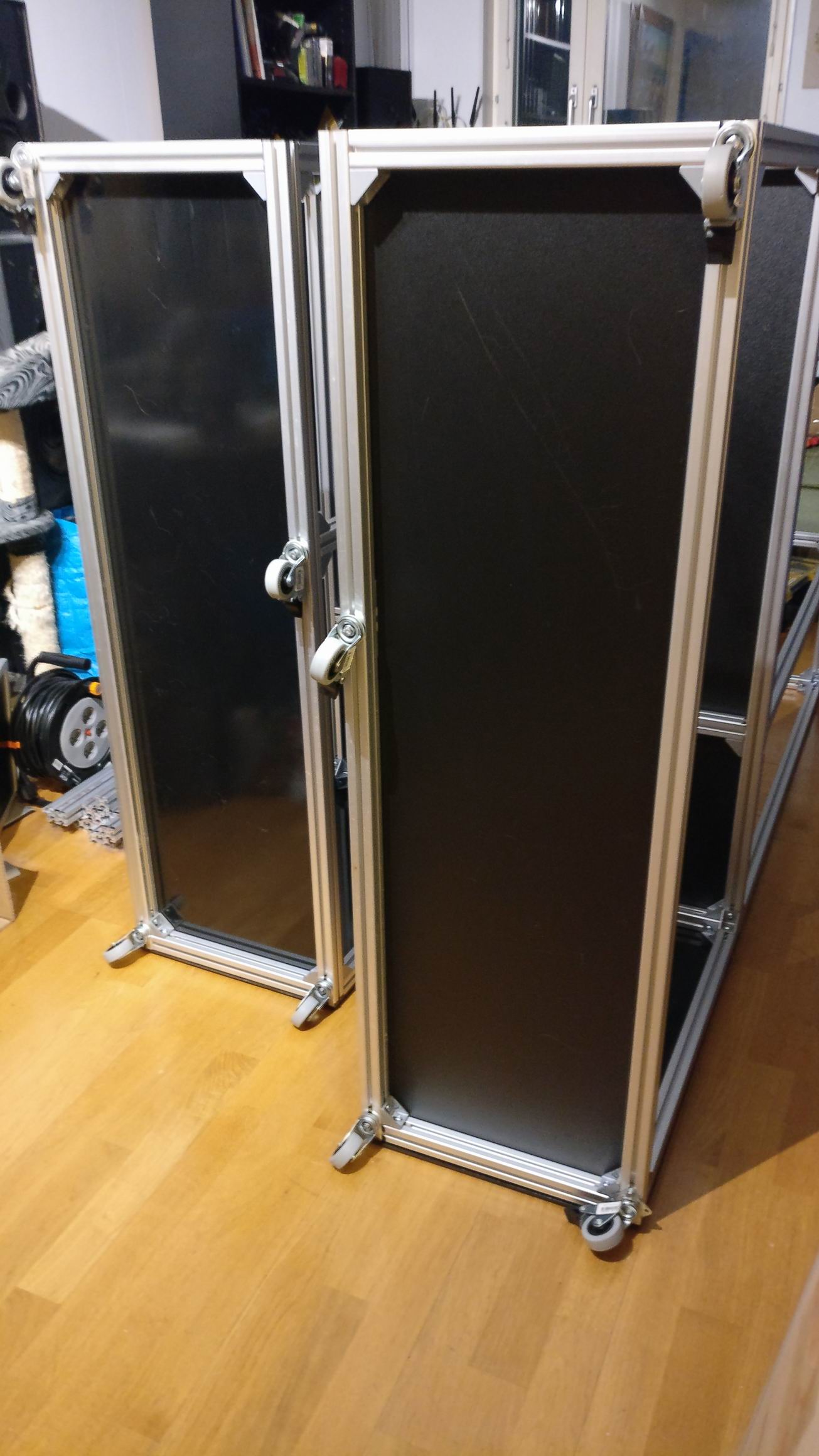
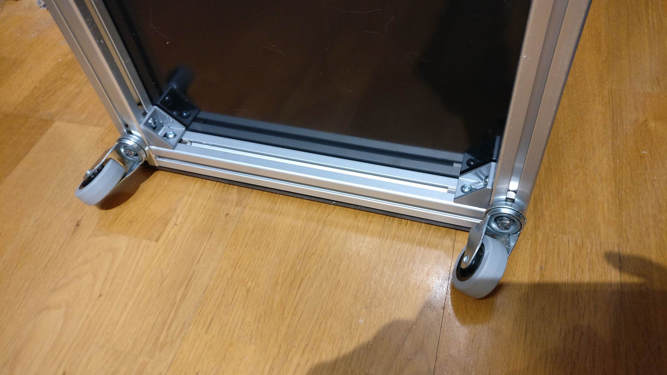
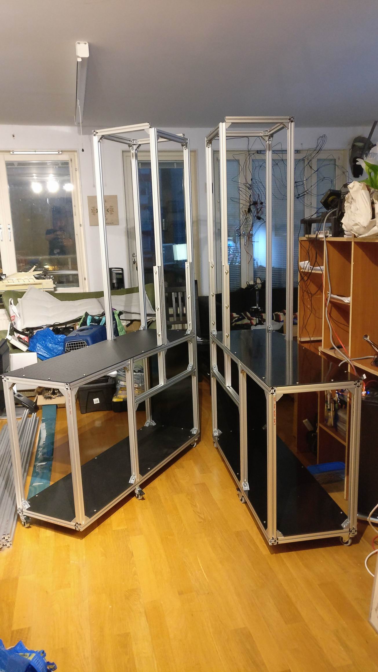
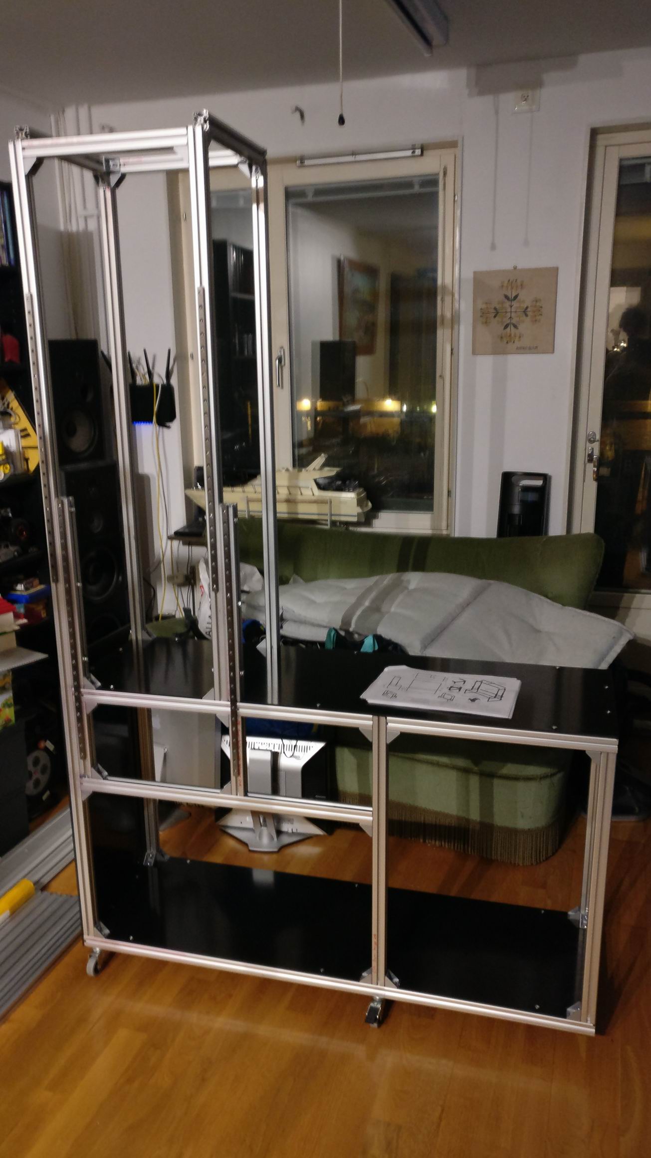
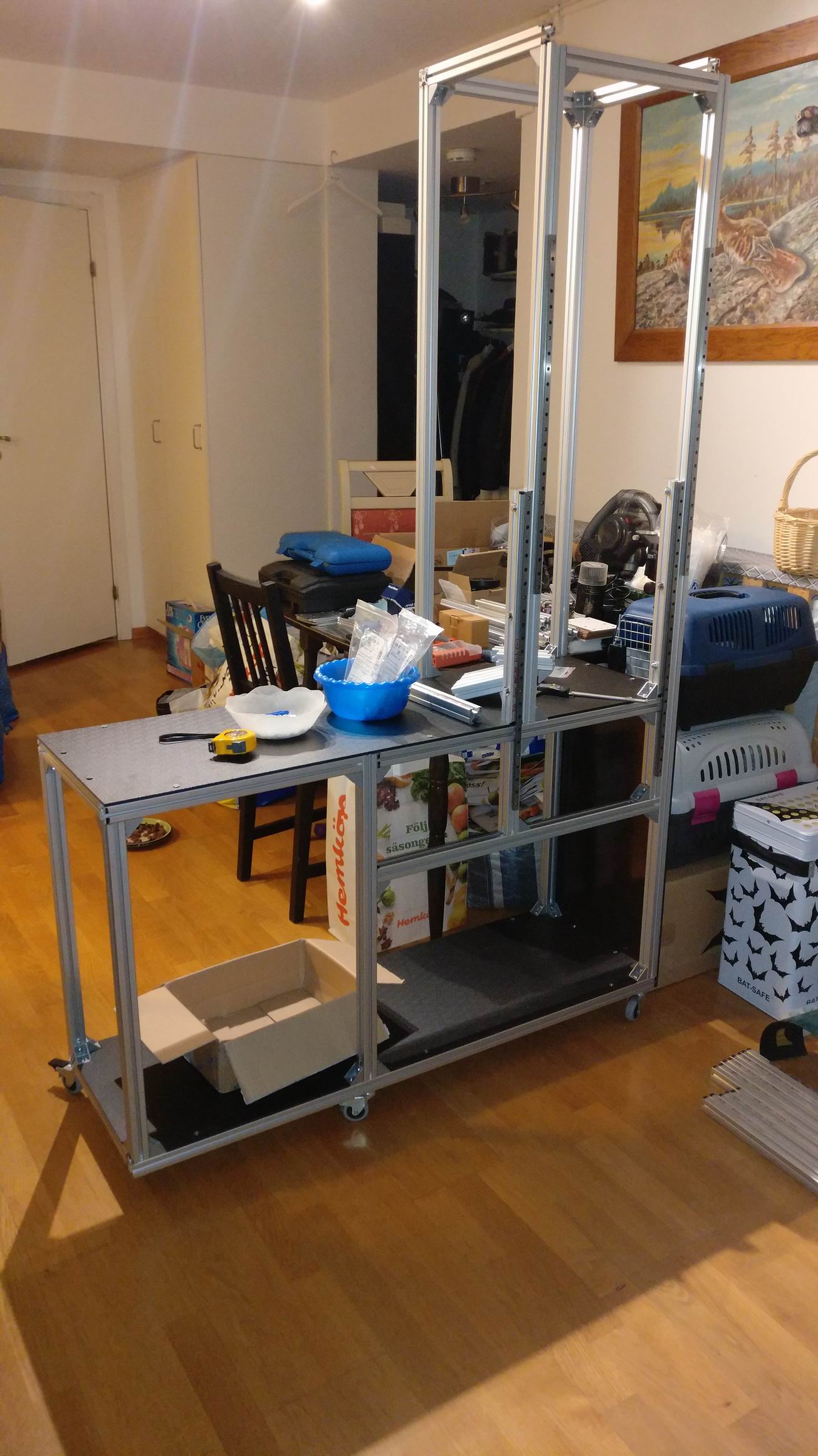
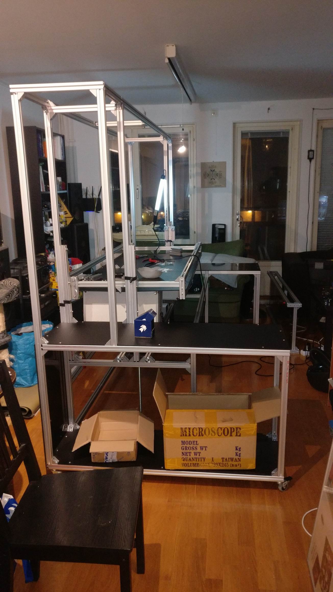
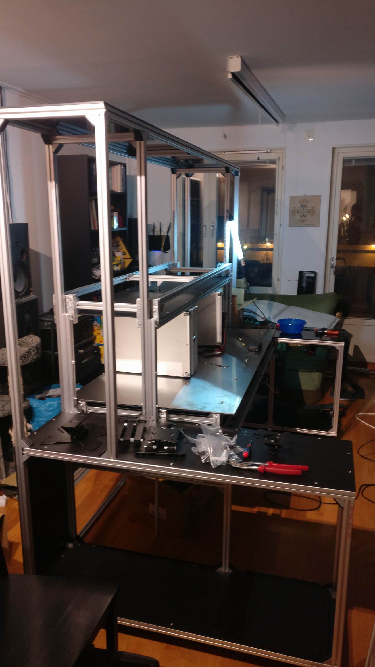
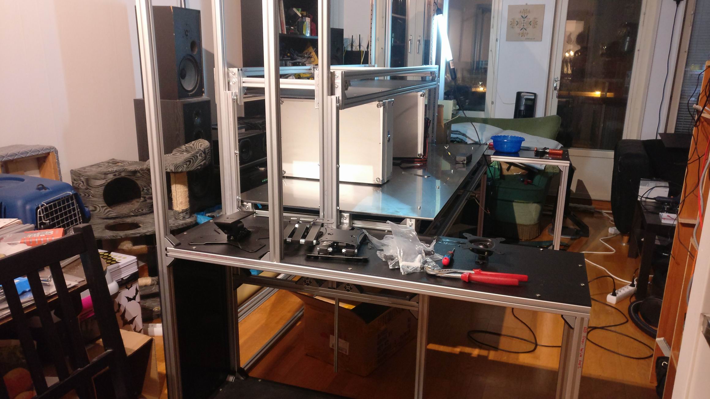
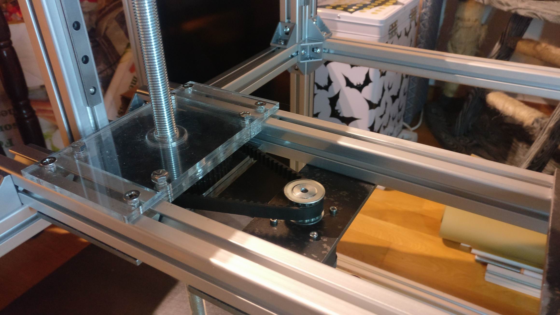
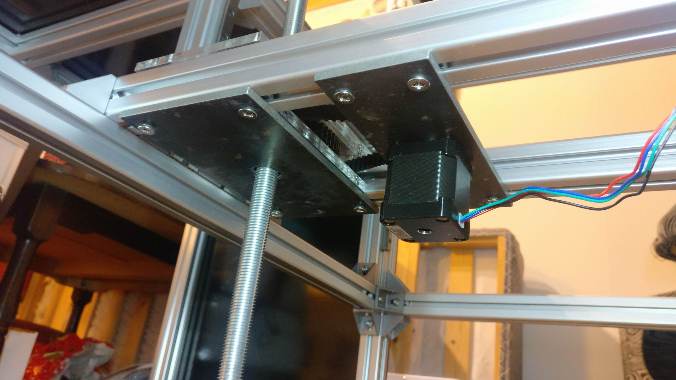
Chassis

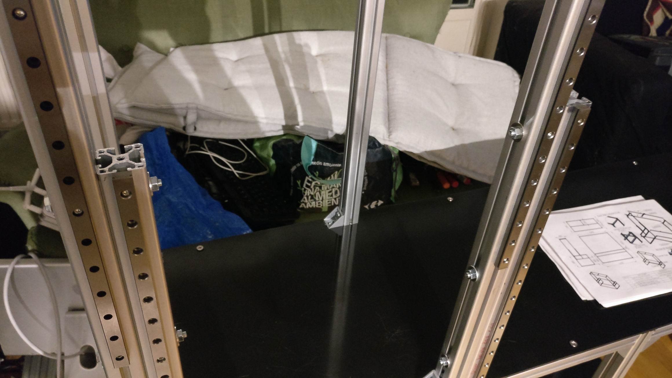
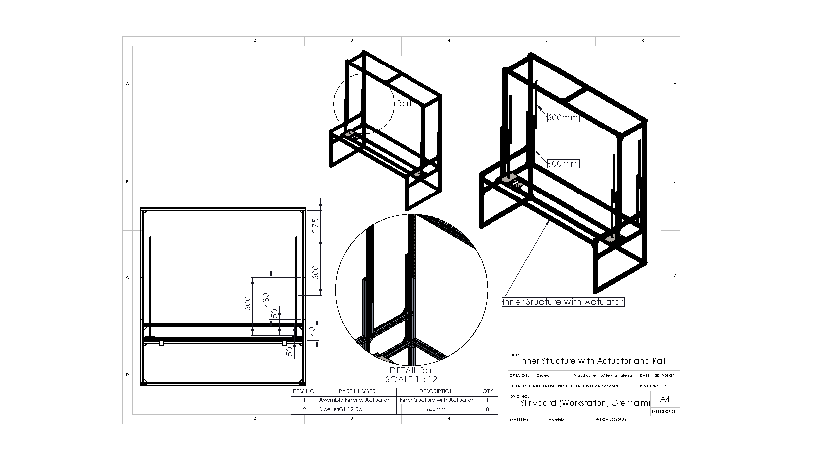
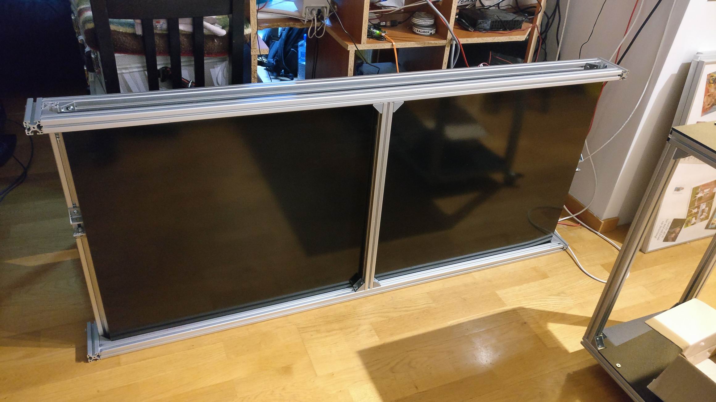
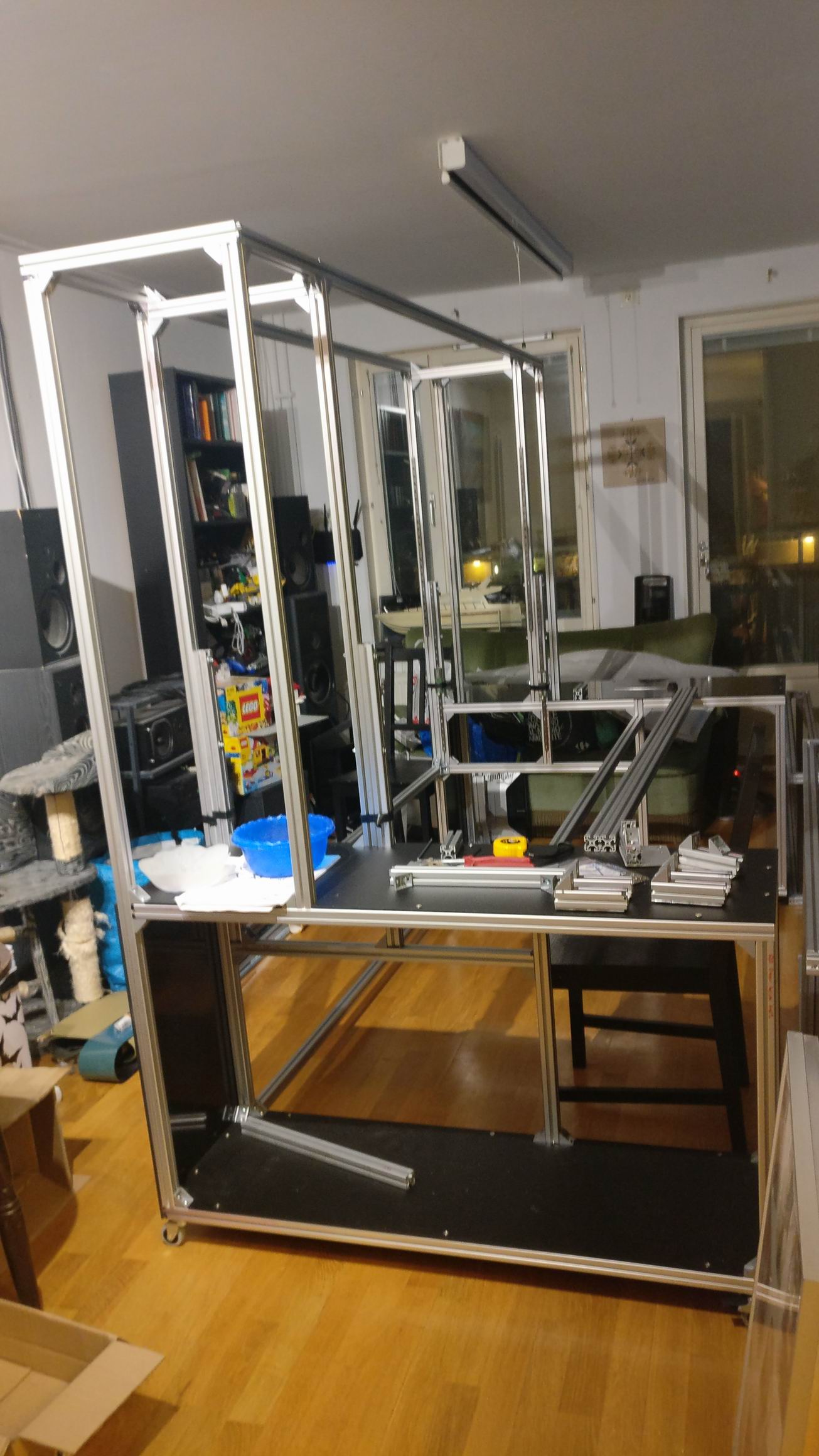
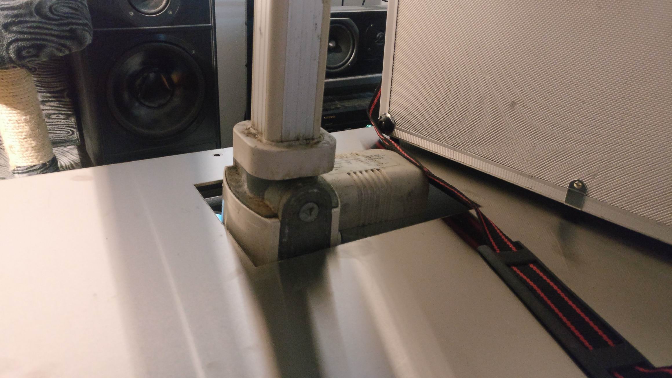
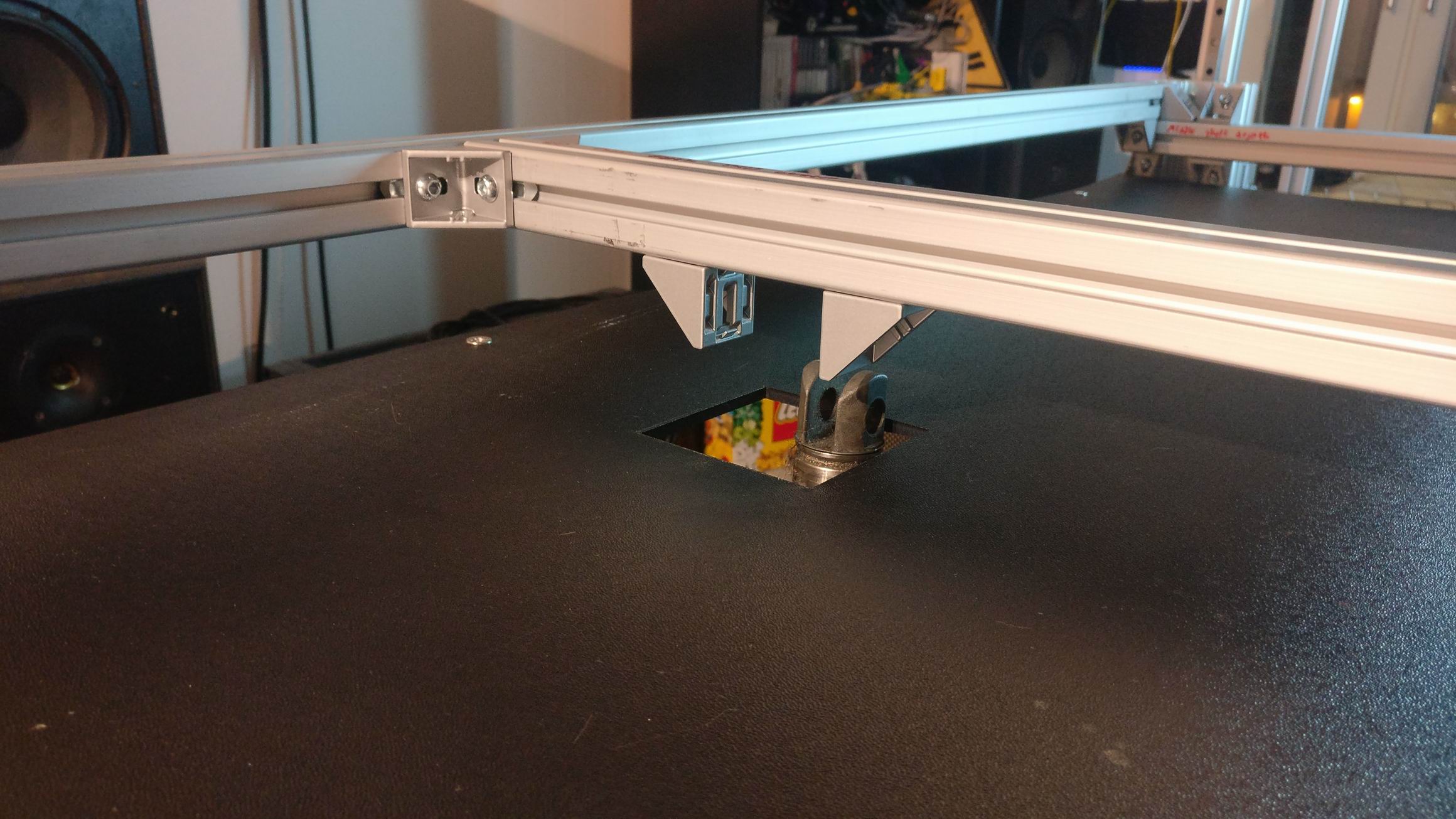
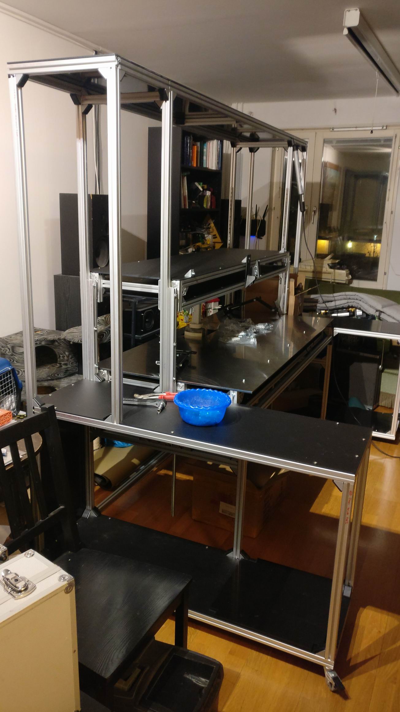
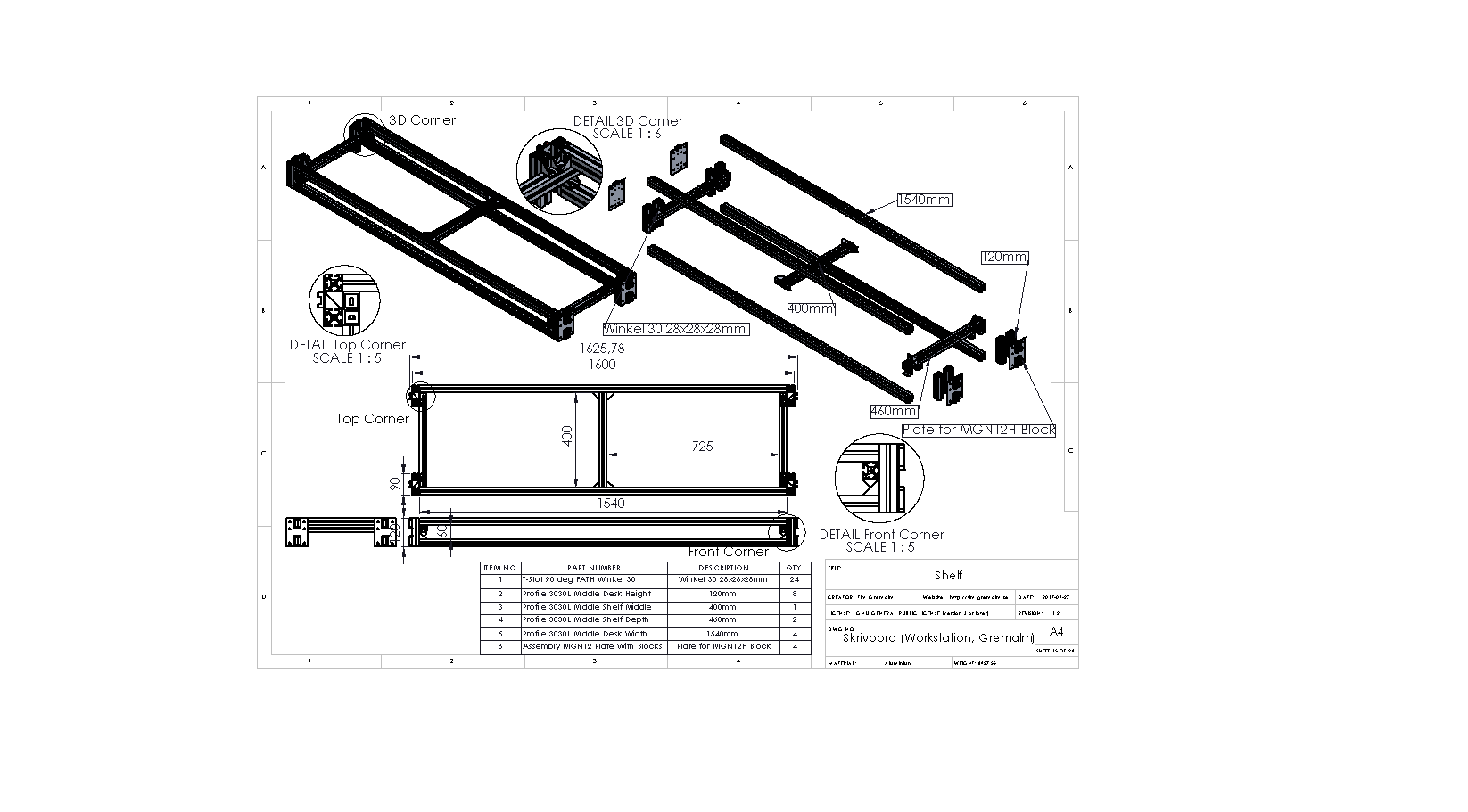
The chassis is build up of 2020 aluminium profile and can be folded to take up less space when transporting.
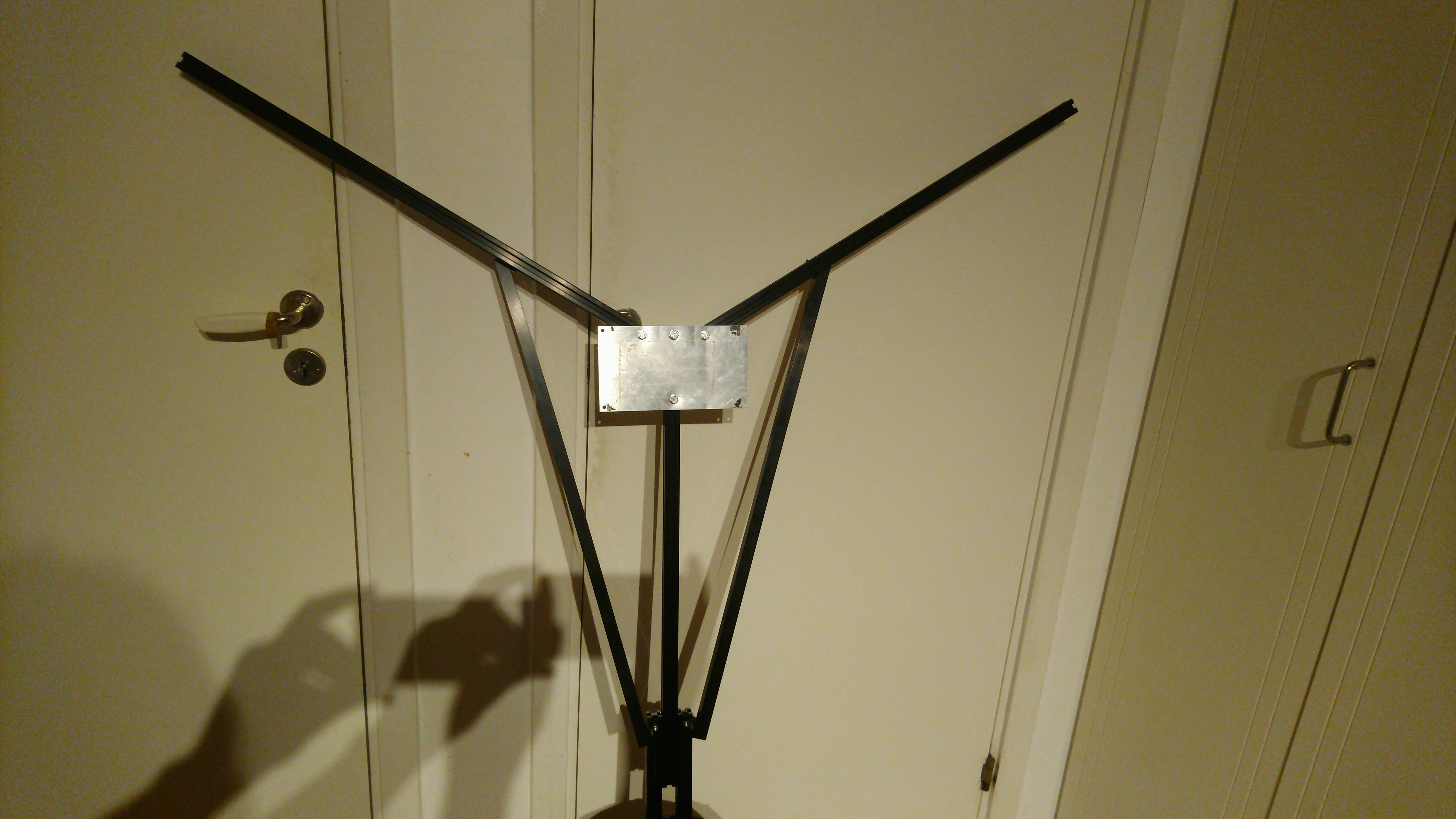
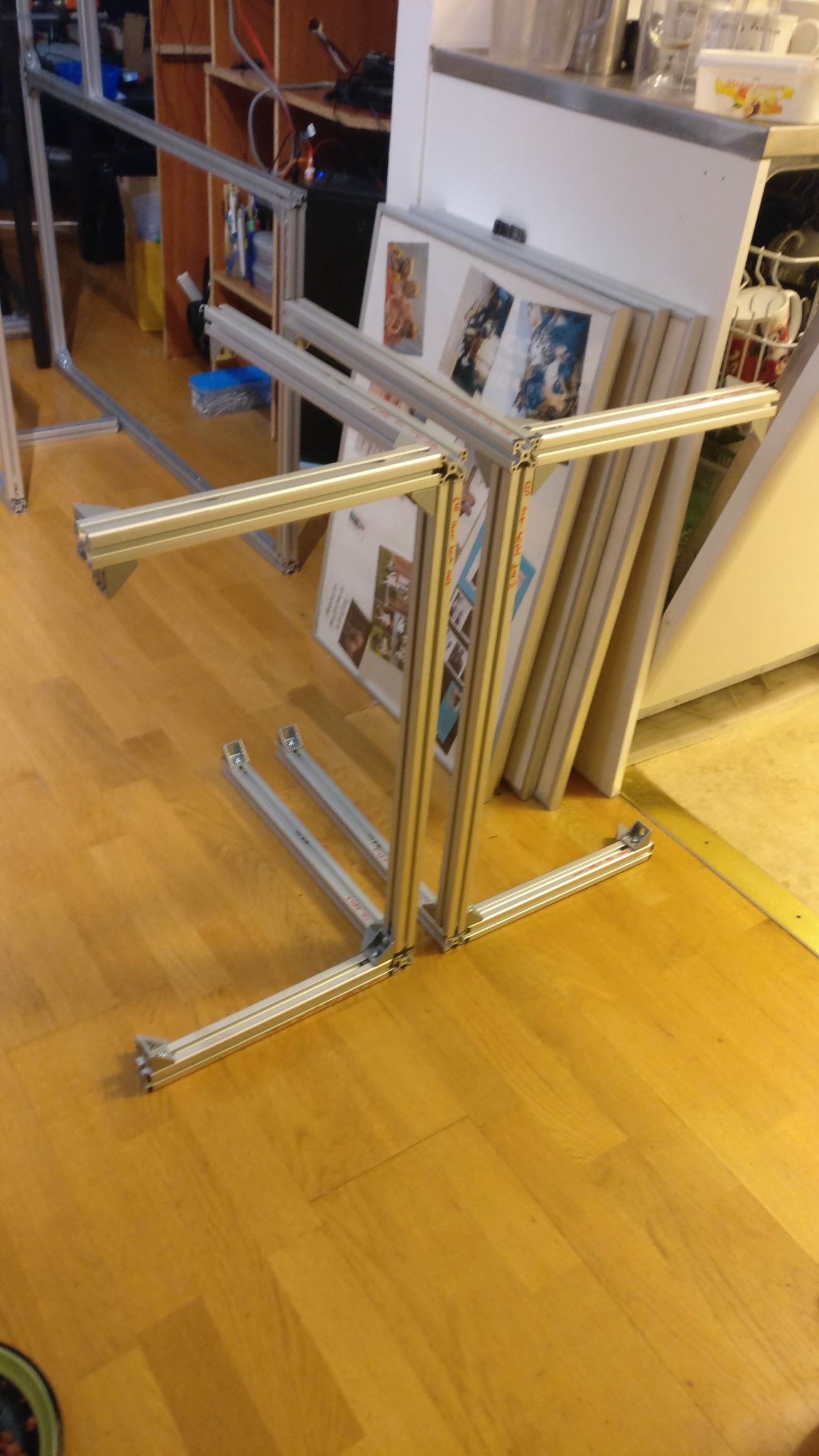
The main section is the Y-arms that is made to carry mini spot lights.
The arms can be raised and lowered, also the whole Y can be raised and lowered.

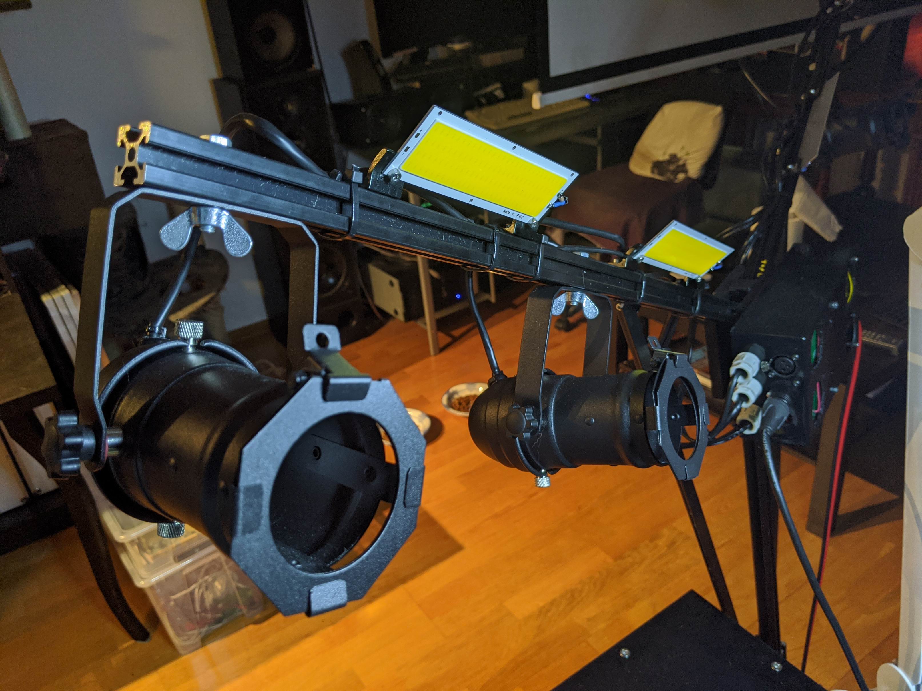
PAR Cans
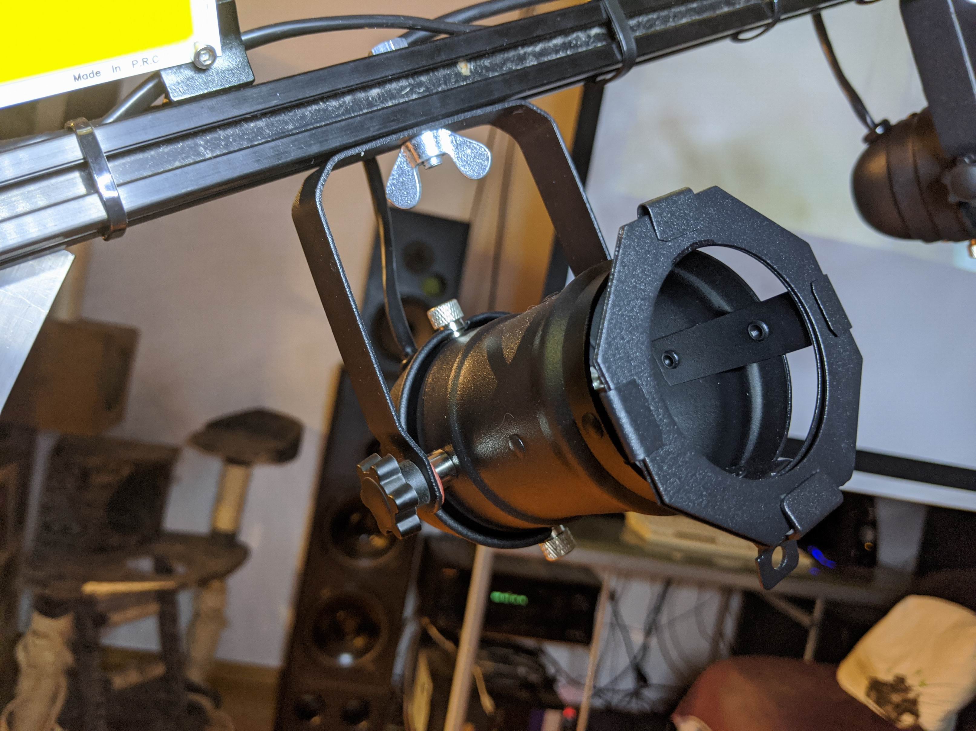
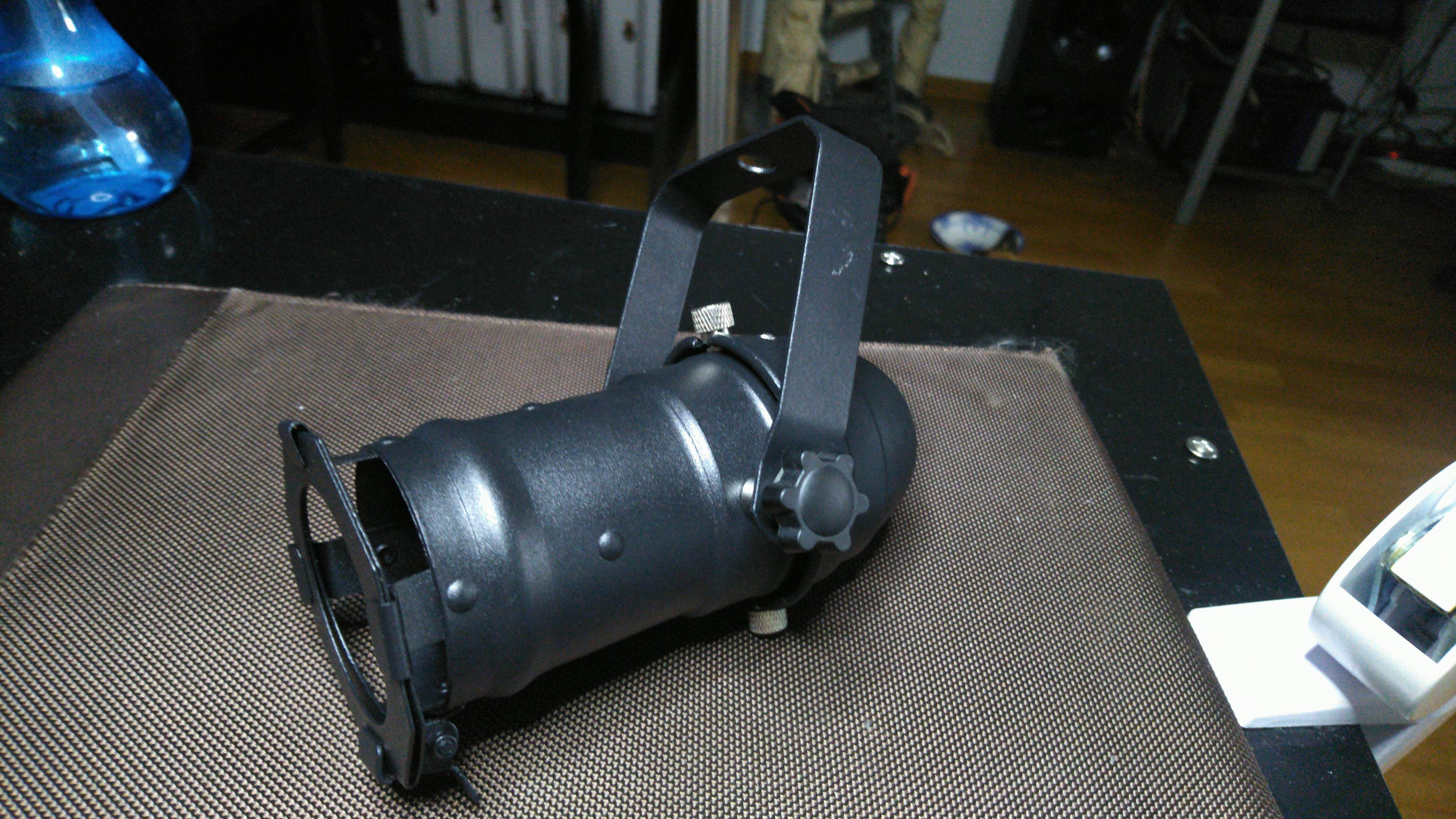
The body of the PAR Cans is a small product intendet for GU10 halogen lamps.
Black 230v Mains Pulse PAR16 Birdie Can Parcan Lantern DJ Stage Spotlight
My idea was to tear out the halogen part and exchange it with LED’s instead. It worked out okay, but it was very fiddly.
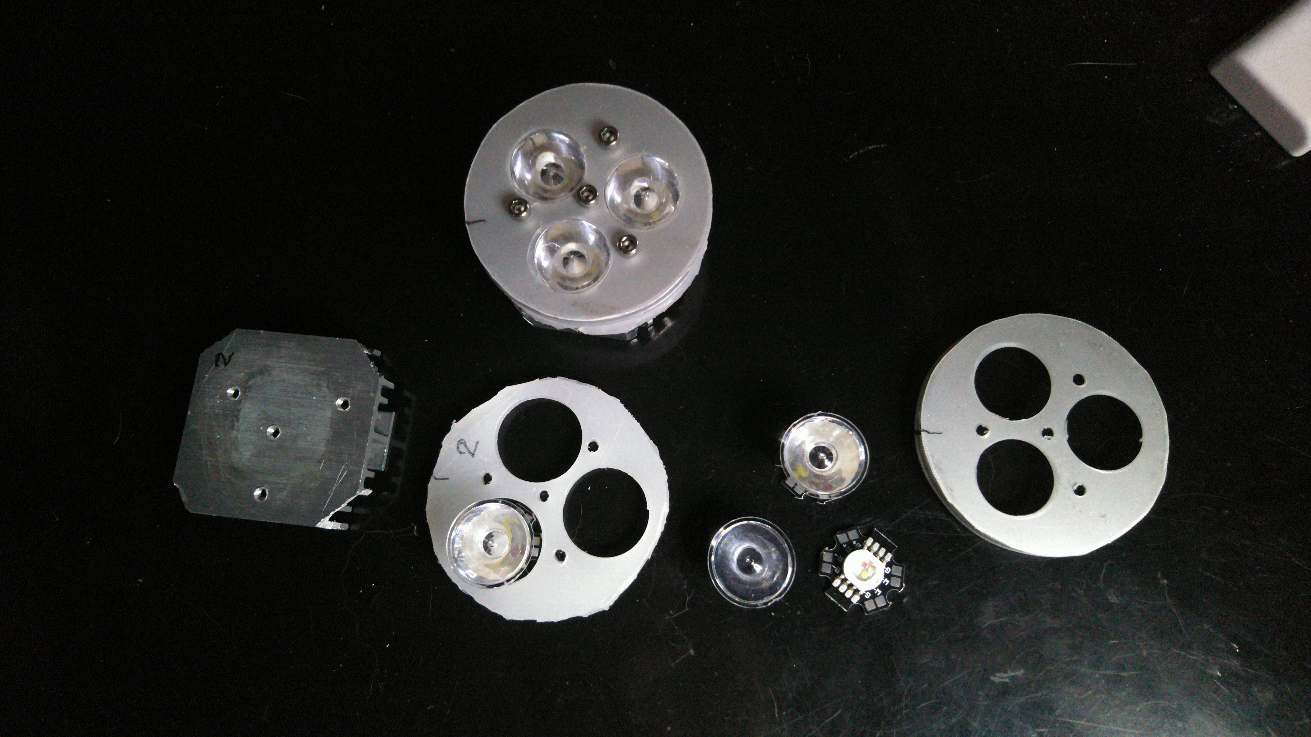
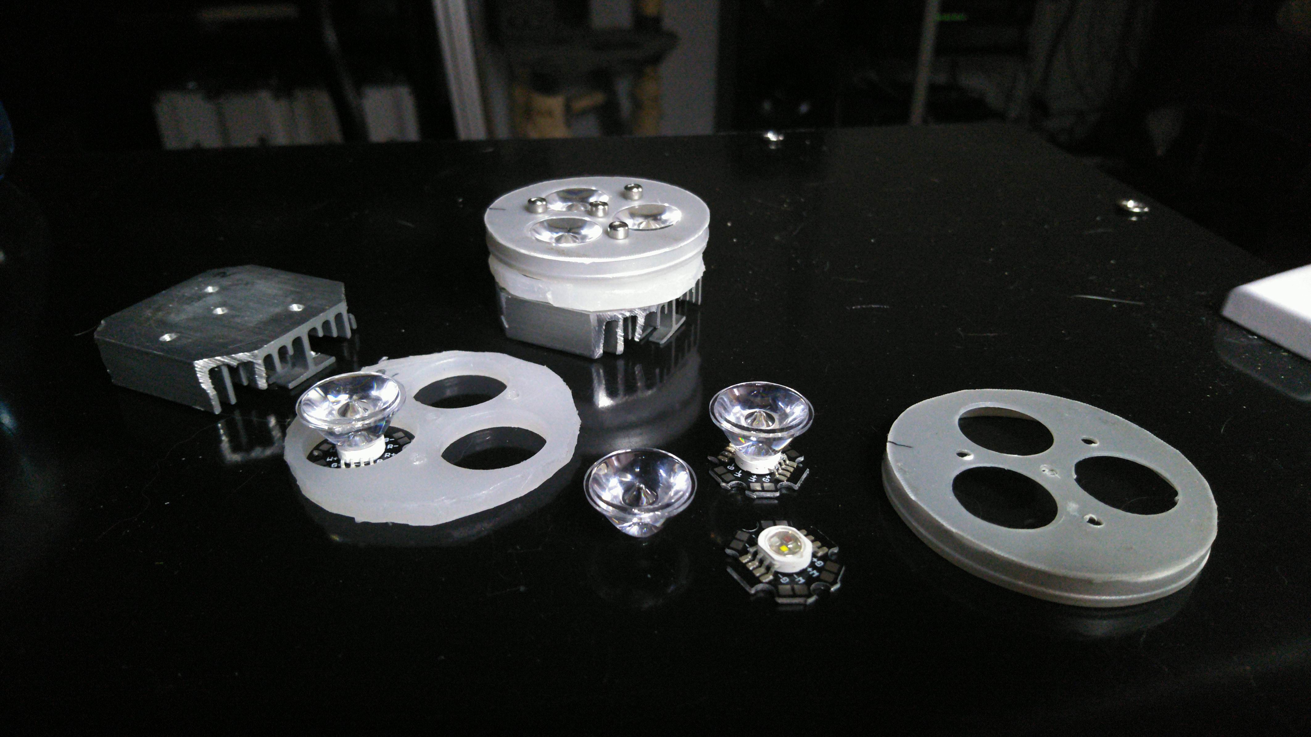
The LED assembly is basically these layers bolted together:
- Plastic lid
- Collimating lens 5 degree 21.8mm
- Star LED RGBW 4W
- Plastic holder for LED’s
- Heatsink 45x45mm
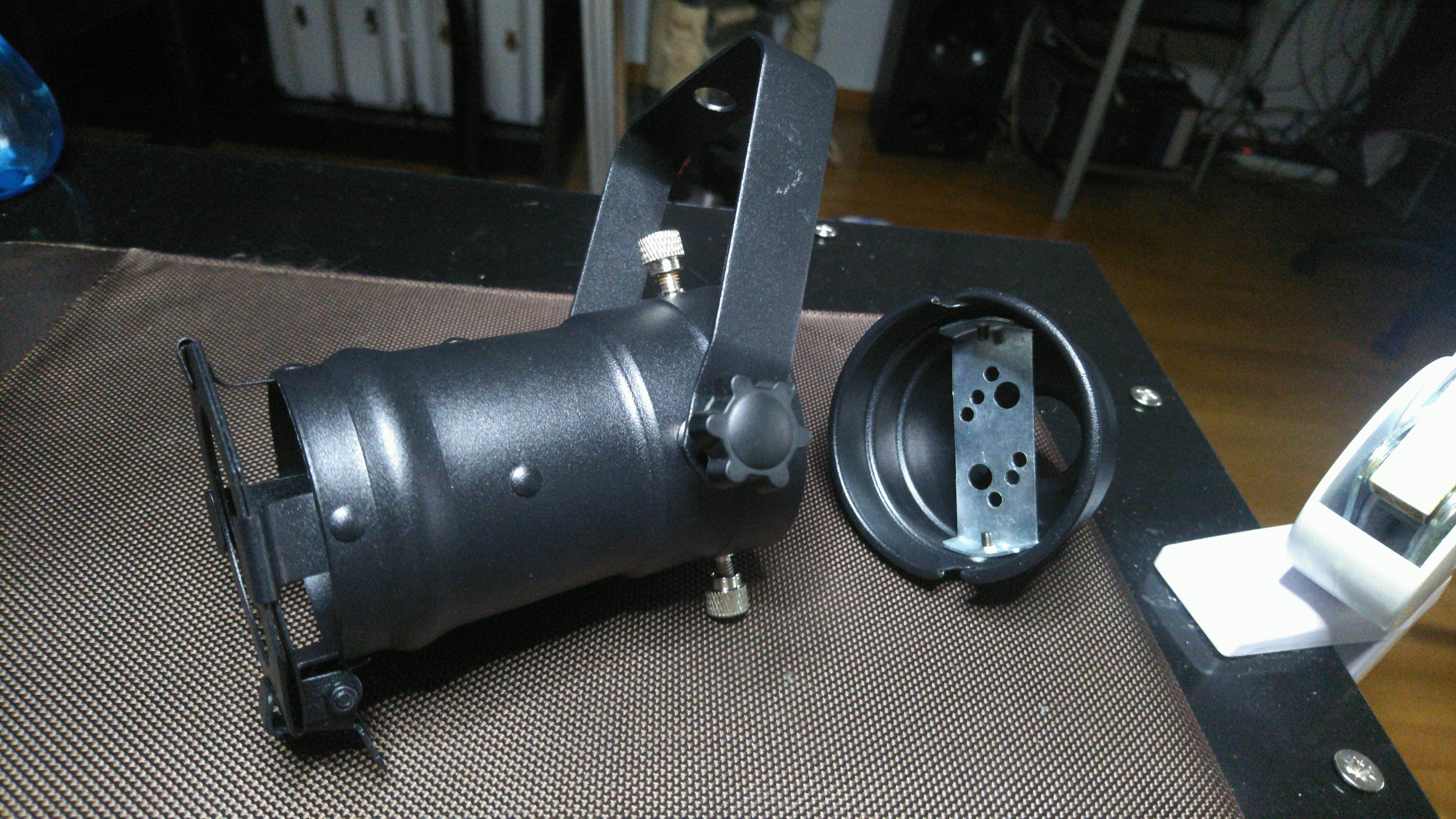
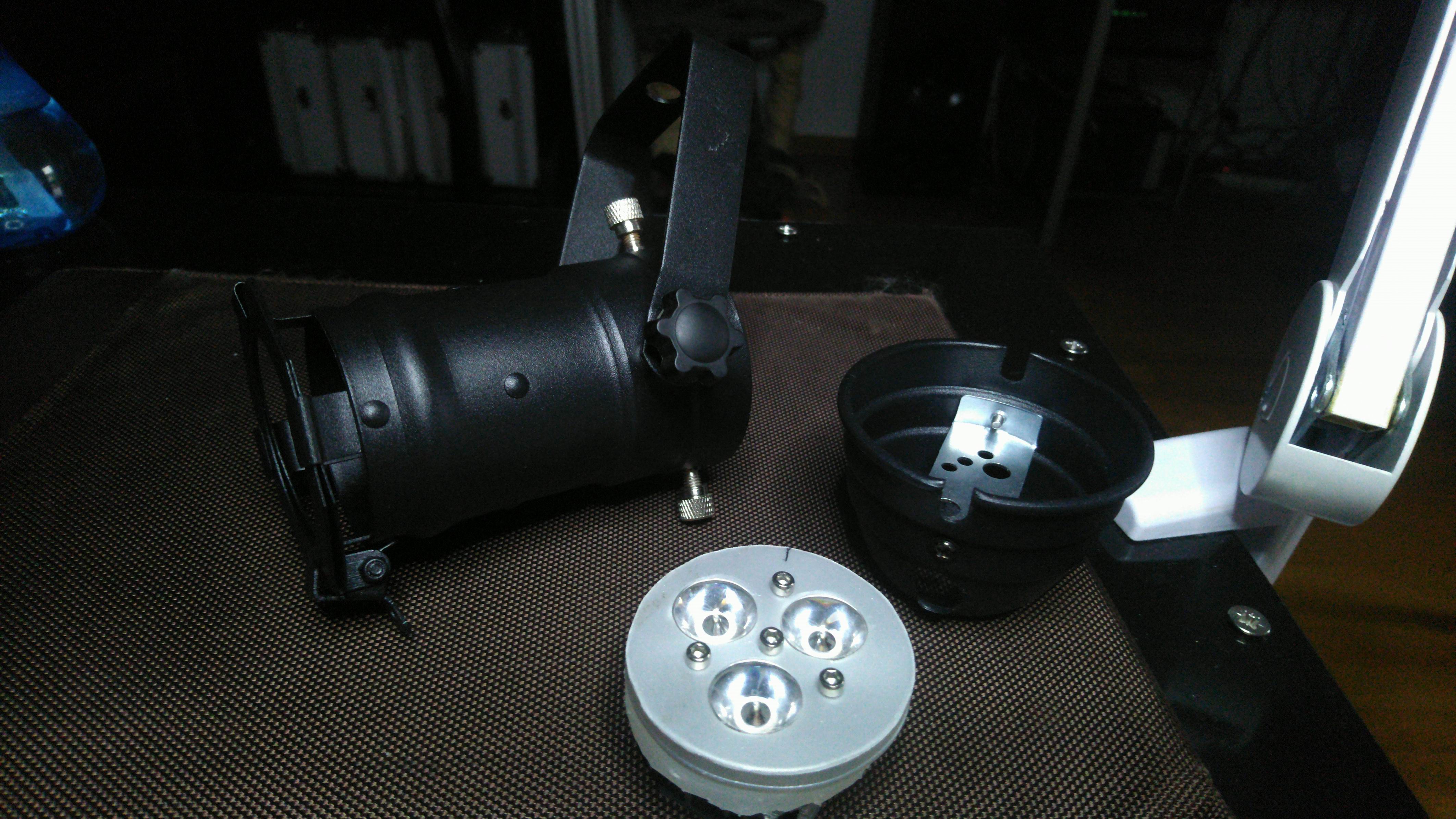
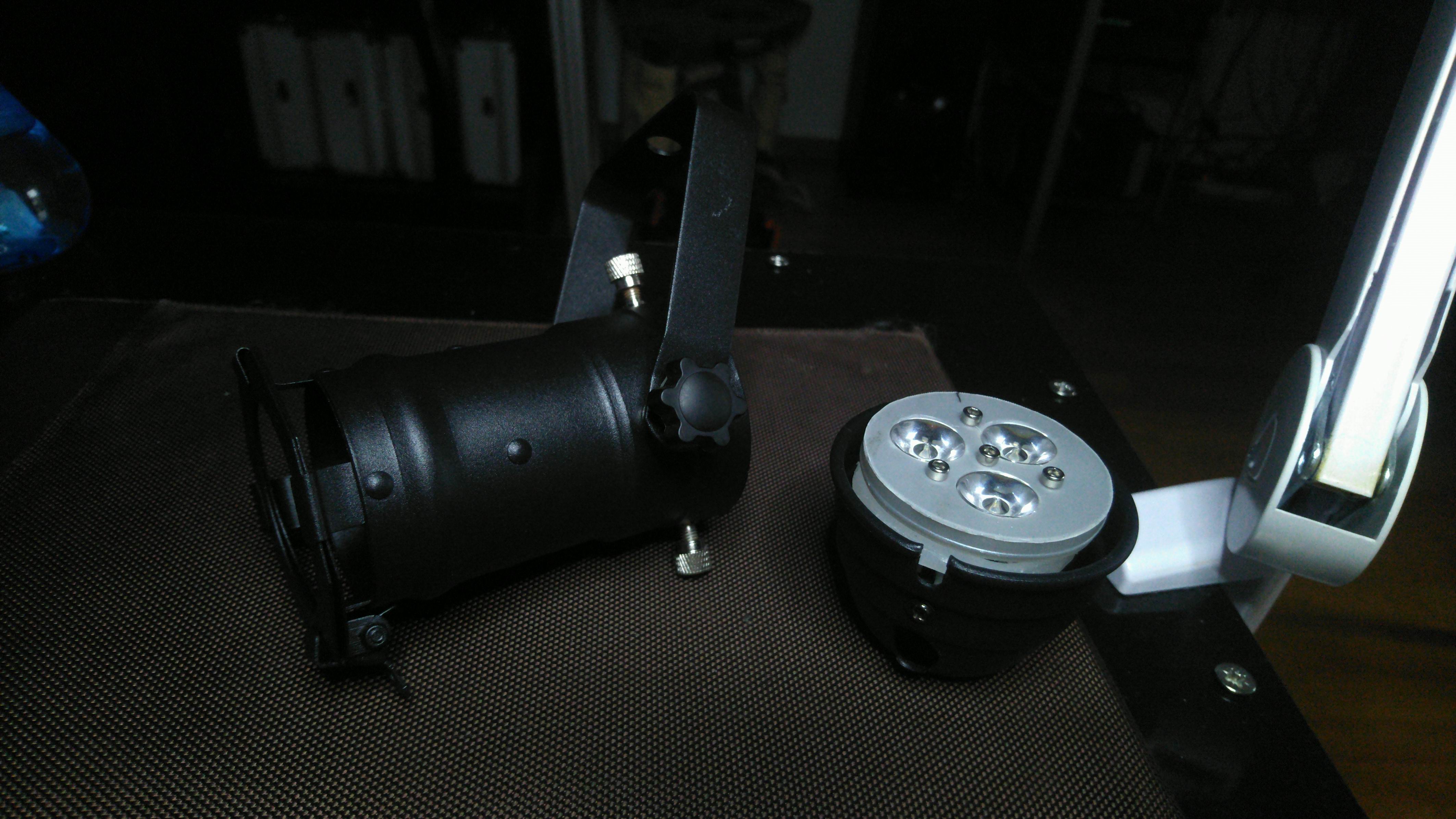

The LED assembly pretty much replaces the old halogen GU10 base. Then the whole back of the PAR can be mounted as before.
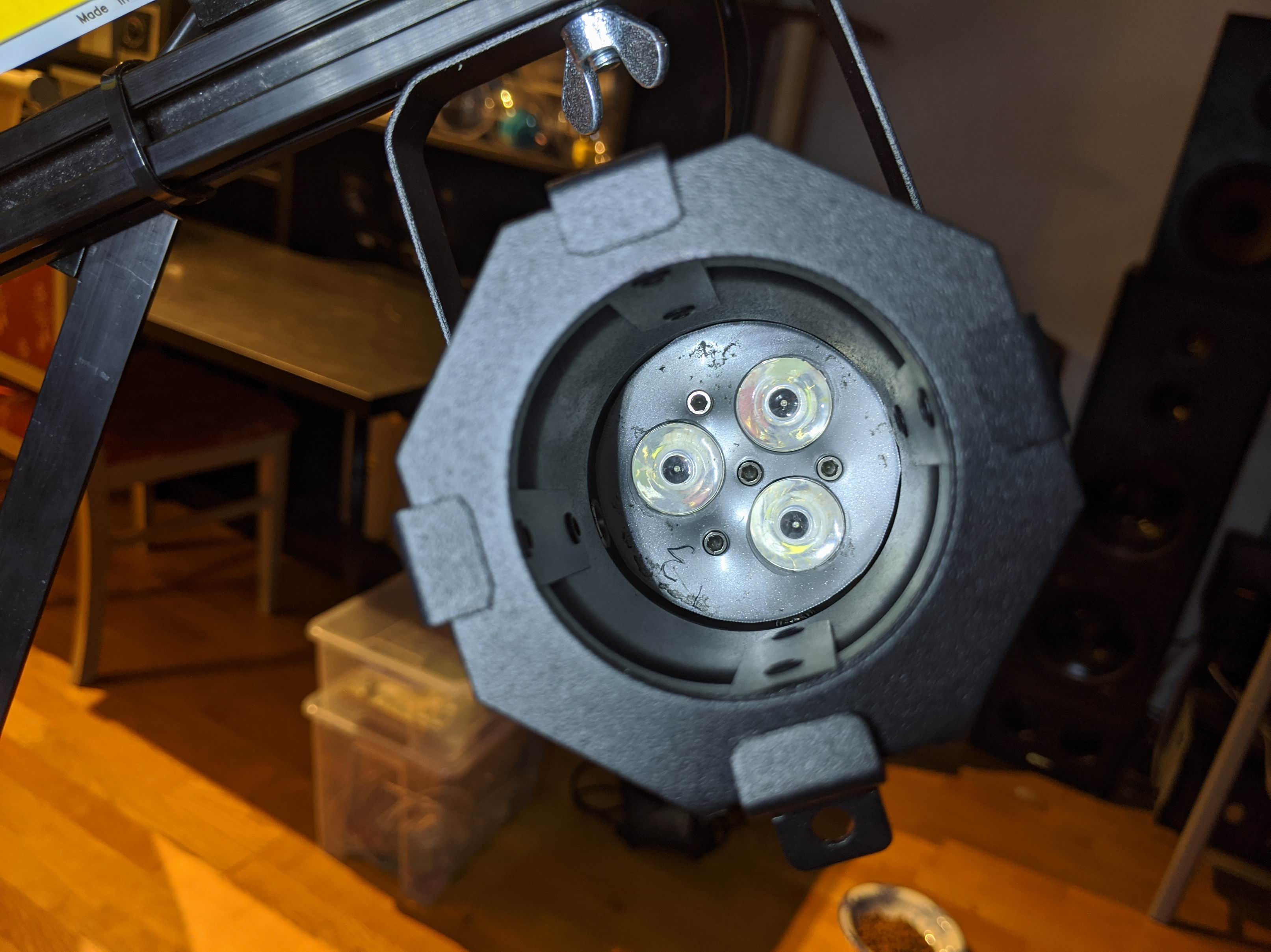
The angle of the 3 LED lenses titling inwards a bit, that means that the light beams overlap a bit. The natural tube shape of the PAR cans absorb any lights escaping the lenses which get rids of the halo-effect that so easily can occur.
PAR Can LED drivers
I went with a little unusual LED driver for this build. Since this is a battery operated product I didn’t want to limit the current with resistors and loose a lot of effect on them. Especially since effect of the LED is 1W per color channel.
I decided to limit the current consumption of each color of the LED by supplying it’s forward voltage from a buck regulator. By simply adjusting the voltage in the buck I could trim it to around 200mA per channel.
The extra potentiometers in the bucks would also give me the option of adjusting each color channel separate. That made the color calibration of the light so much easier.
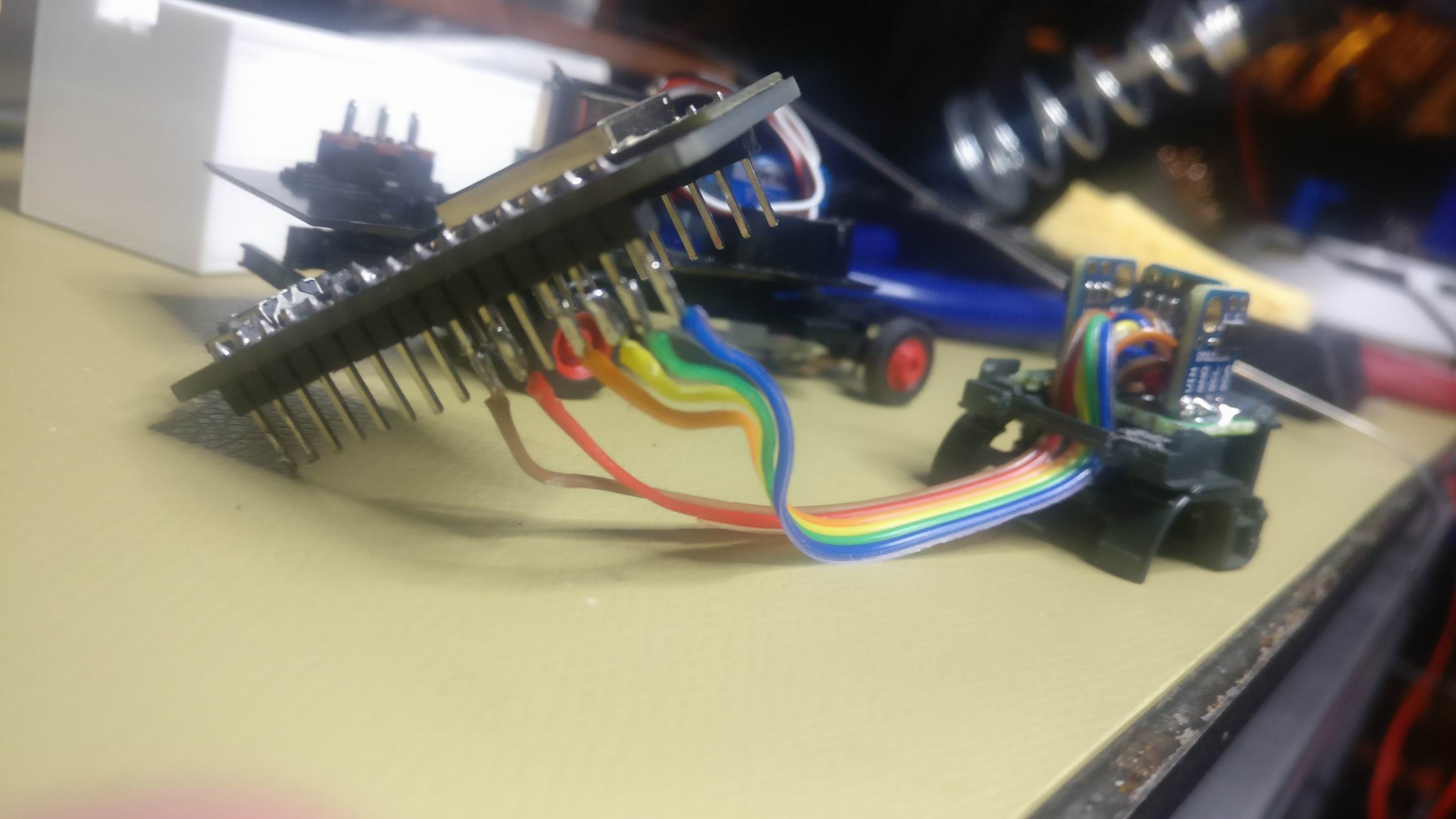
I also find a cheap and available power cable; I used a ethernet cable. It comes in 4 twisted pairs with colors almost matching red (orange), green, blue and white(brown). According to Wikipedia a 24AWG ethernet conductor can handle 0.577A. The ethernet cable worked great, my current is about 200mA.
The maximum current rating on the LED’s is 350mA. I decided to put 3 of them in series at around 8V, that would also lower the current and make it easier for the ethernet conductors.
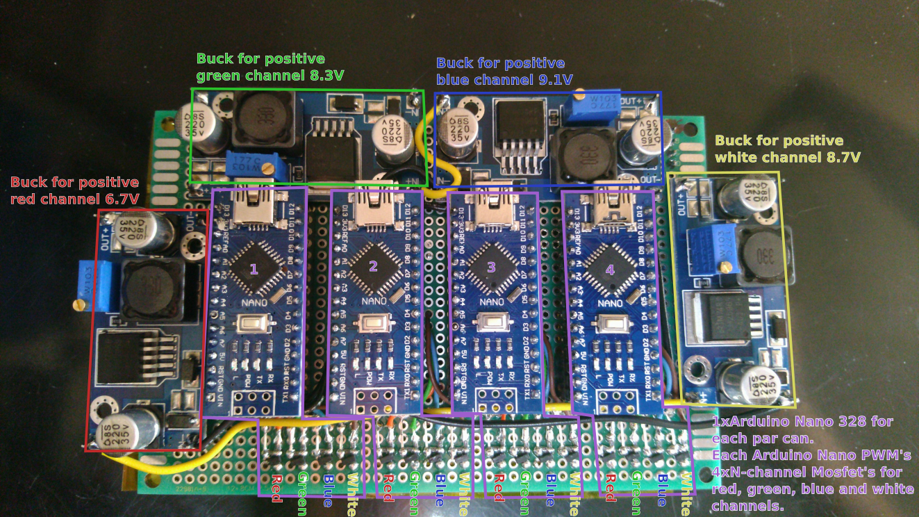
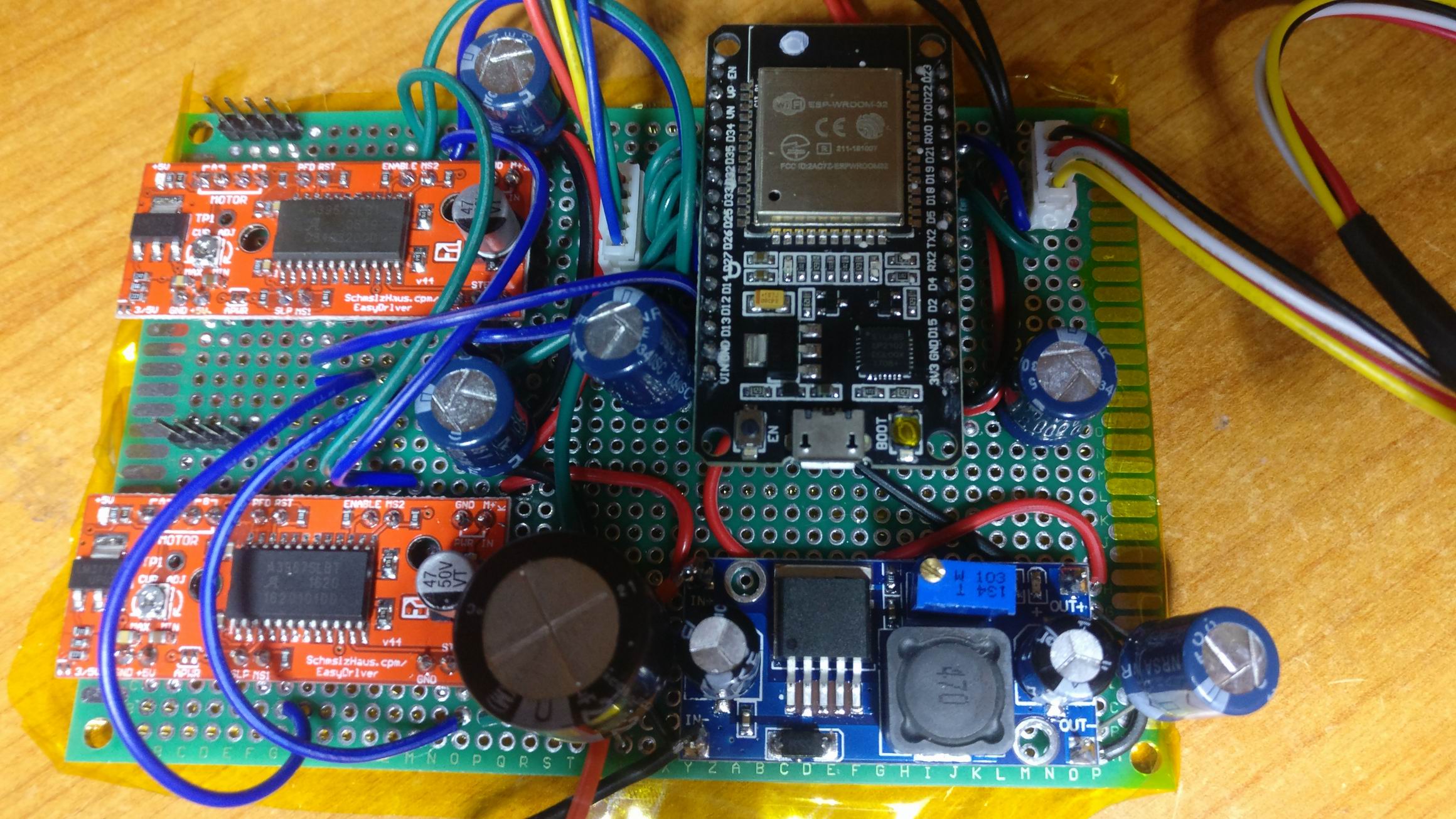
The PCB for the PAR lights consists of 4 Arduino Nano 328p that controls the PWM to RGBW for the 4 PAR cans. It also holds 4 buck converters for corresponding color.
The LED’s packaging have 8 pins that leads to separate anodes and cathodes on each color channel in the RGBW package. That is a little bit unusual, most packages have a common anode (positive) and separate cathode (minus) to control the LED on the low side.
My setup is a little bit unusual since i don’t limit the current via resistors but set the voltage per channel on the anode side. The 8 pin packaging allows me to have a separate voltage dependent on the color and still use simple N-channel mosfets to PWM on the cathode side.
I used 4 Arduino Nano because one of them don’t have enough PWM outputs. It was also what I had available at home at the time.
COB LED
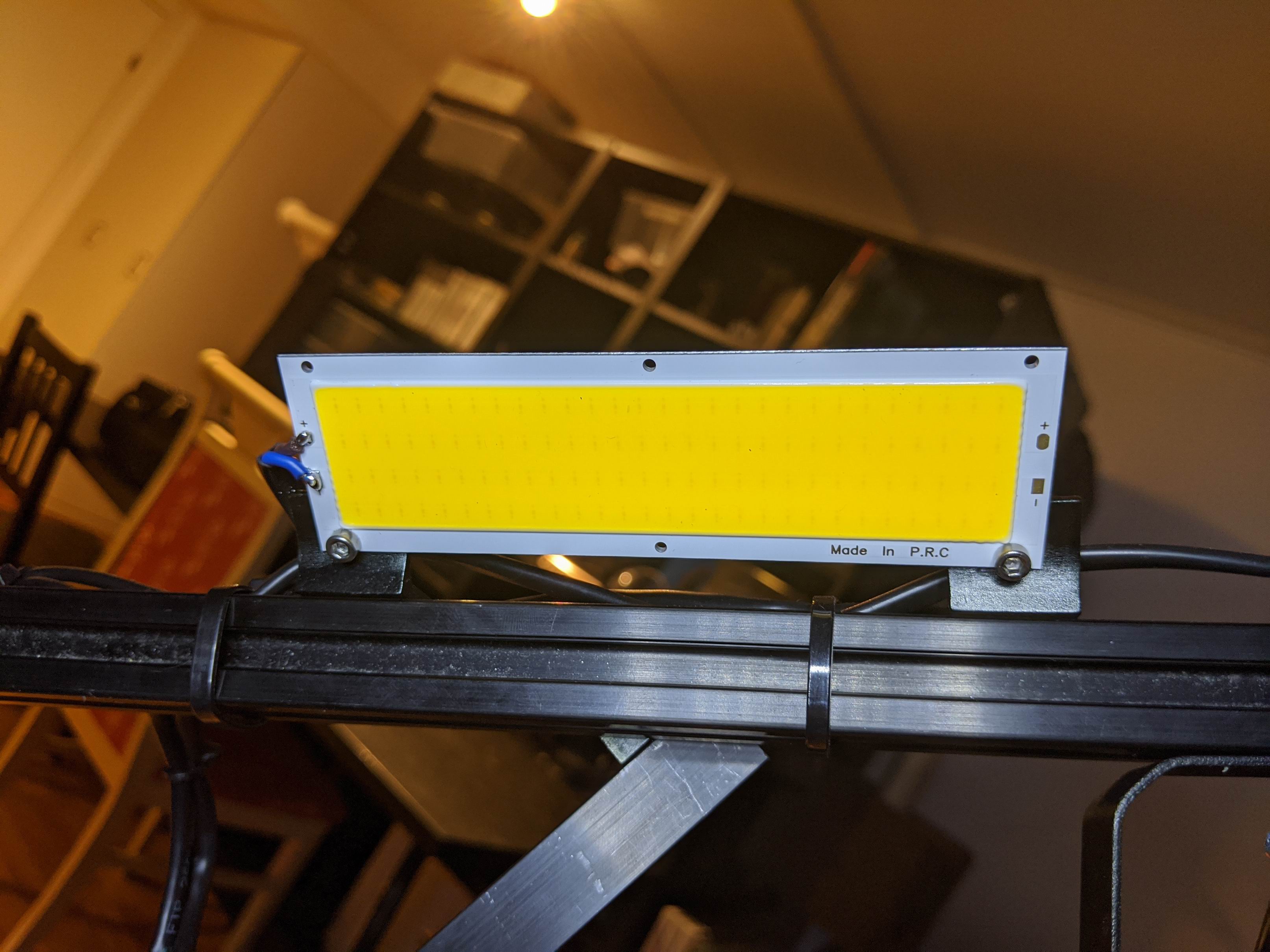
The big 10W COB LED’s goes in between the PAR cans and will act as a strobe and/or blinder.
COB LED Panel 120x36mm Warm White 112 LED 10W 12V is a powerful LED with a big aluminium back for sinking the heat from the 112 LED array.
The mounting was pretty easy with a couple of 90 degree aluminium profile and some screws. I also bended them outwards towards 135 degrees. This light rig will be around 3 meters up in the air, so aiming the blinder downward felt necessary.
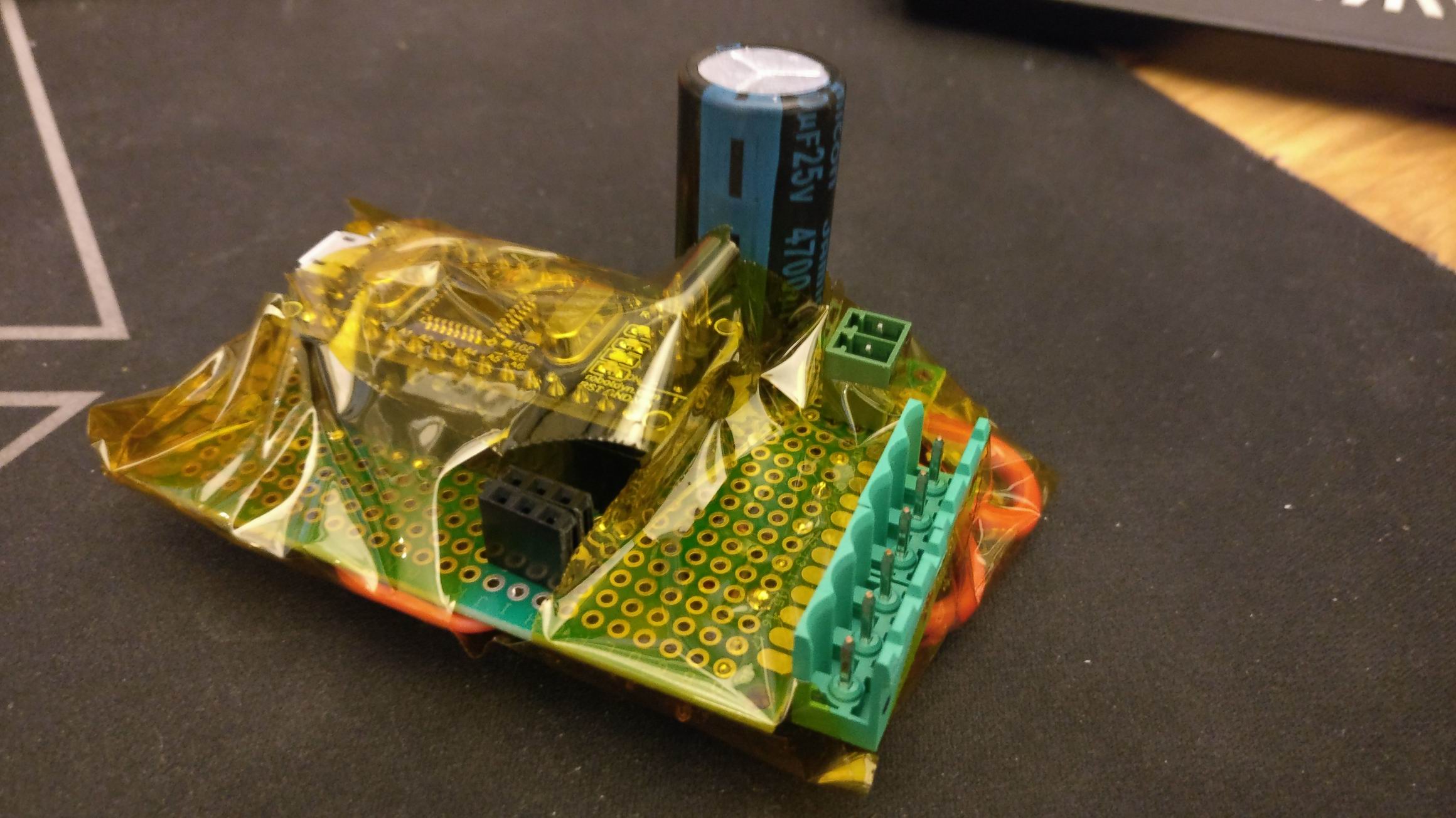
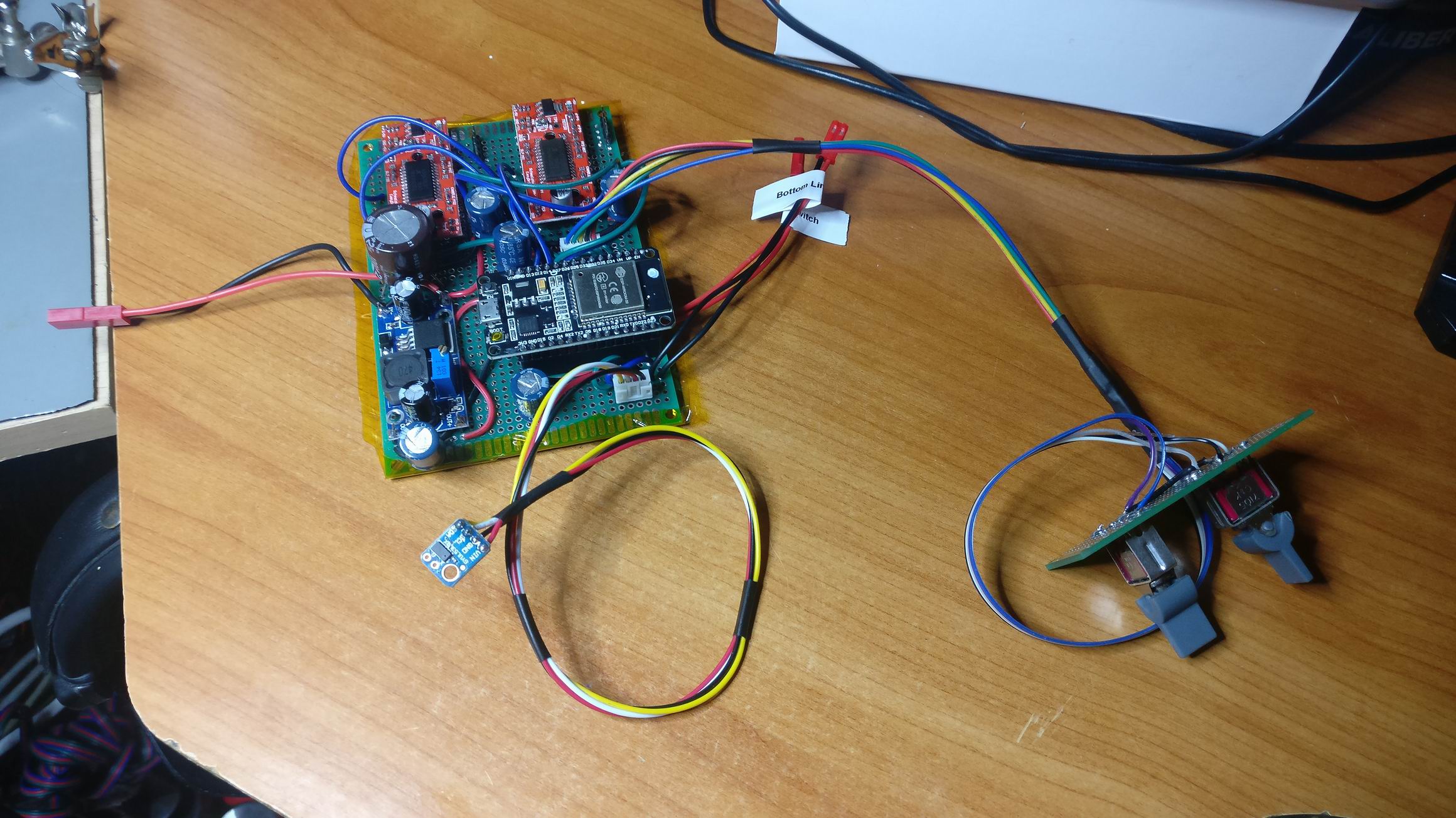
DMX Reciver and COB LED Driver
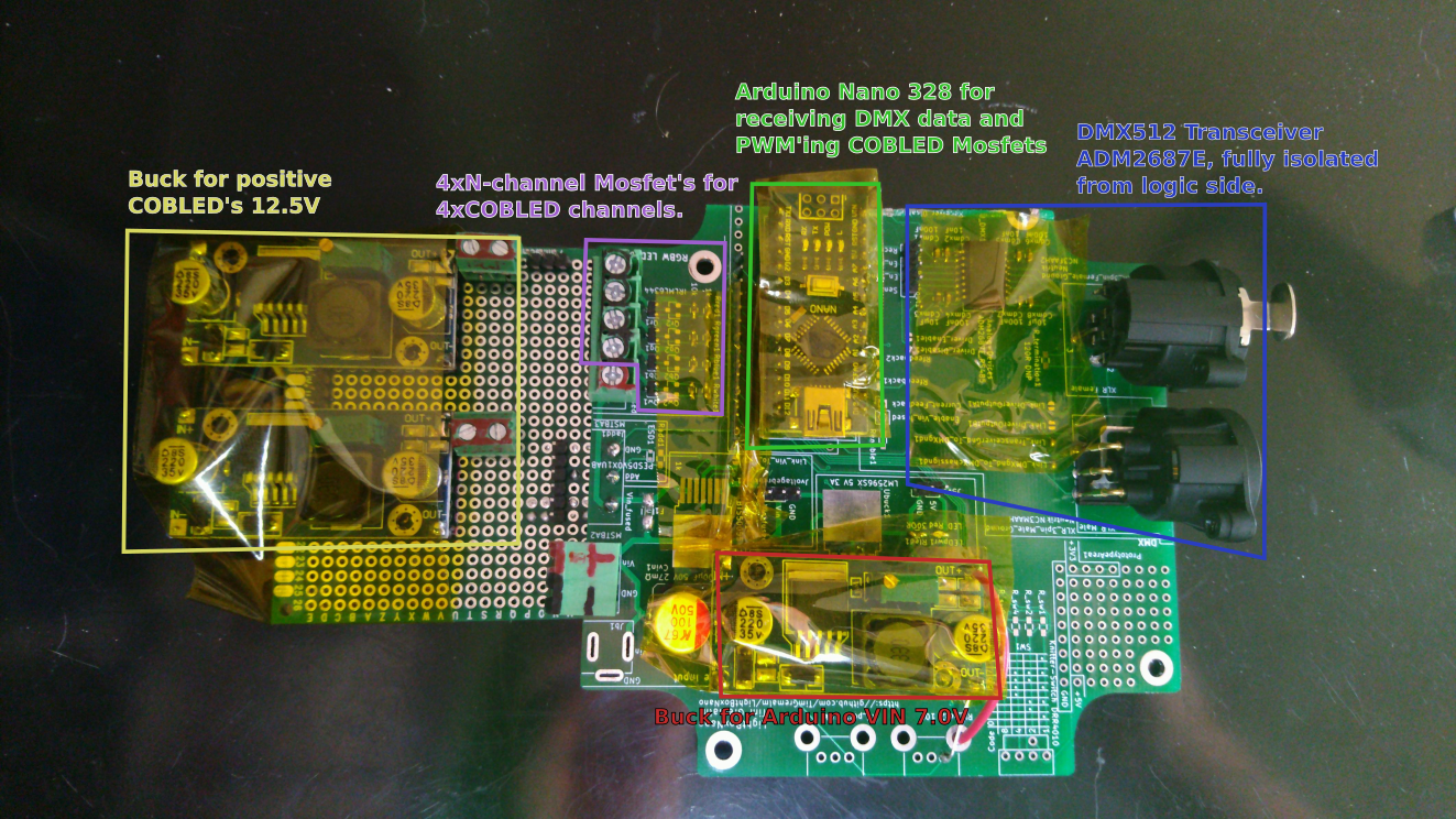
The PCB for the COB LED’s also takes care of the DMX512 light control input. It’s based on a LightBoxNano which is populated with 4 N-channel mosfets and a Arduino Nano.
The LightBoxNano have a RS485 transceiver populated that enables it to receive DMX512. The transceiver is a ADM2687E which have a built in isolated dc-to-dc converter.
Many DIY DMX products completely forgets about the importance of isolation from the MCU side. A DMX bus can stretch hundres of meters in a installation and the probability of getting 230V on the DMX side is a real danger.
On most 230V mains powered devices transceivers solve this by bridging the isolated side with a transformer and AC power. But since this is a battery operated device we don’t have access to AC. The ADM2687E transceiver is around 4 times more expensive than the commonly found MAX485, but the ease of the DC-DC isolation makes it worth it.
I’ve extended the LightBoxNano with some protoboard to attach 2 12.5V buck converters for the positive side of the COB LED’s.
The same driver technique is used on the COBLED driver as the PAR can LED driver. I don’t want to waste energy as heat, and a simple adjustment on the buck’s potentiometer makes it easy to set the current.
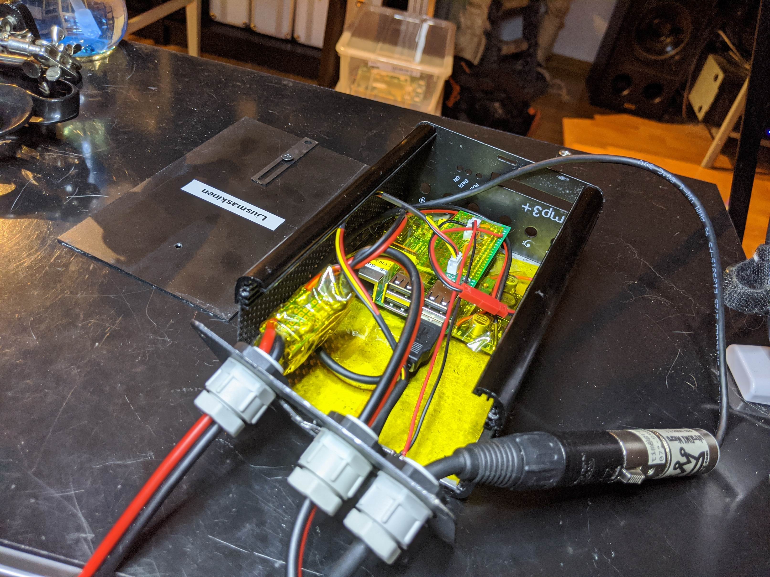
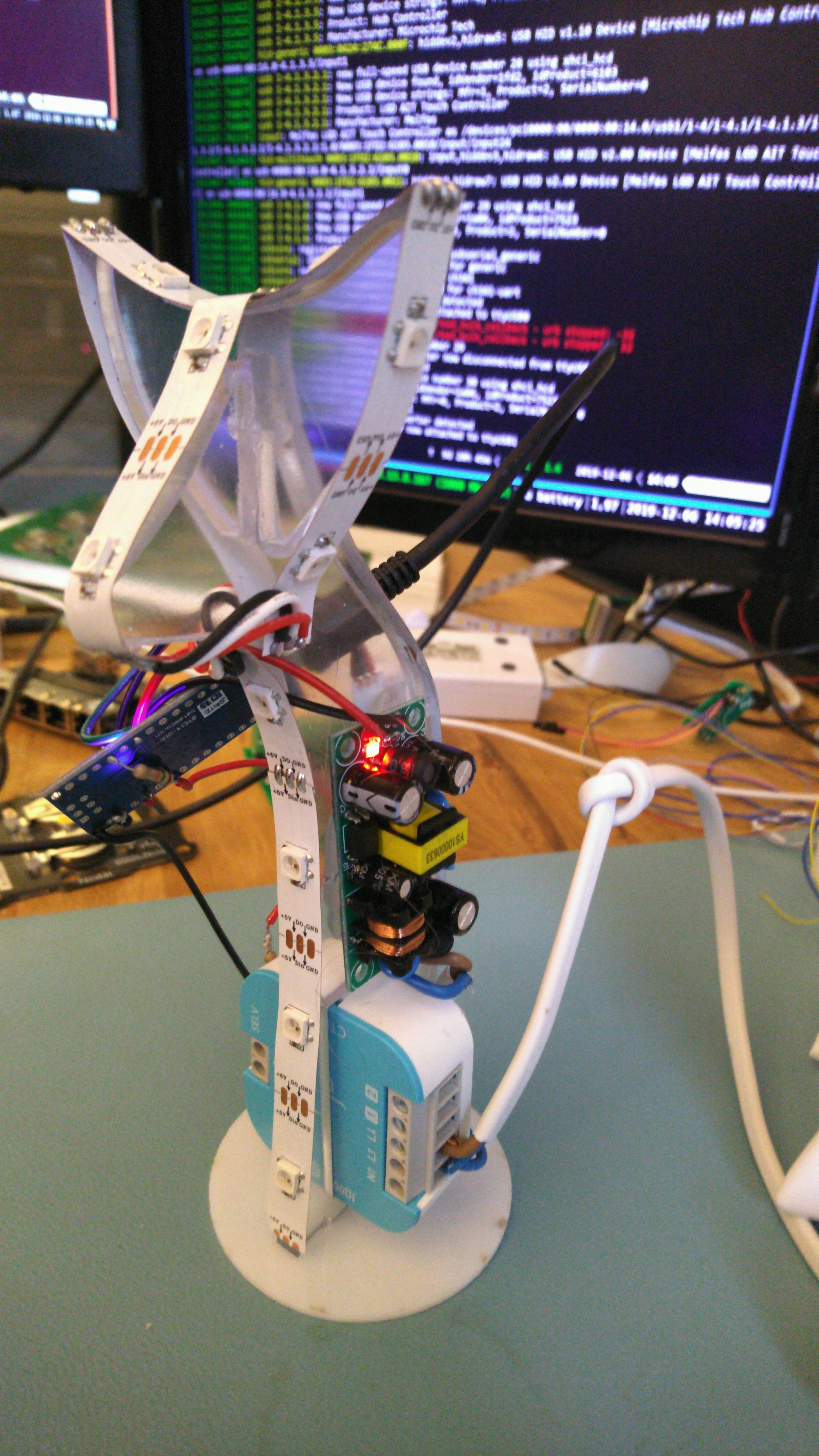
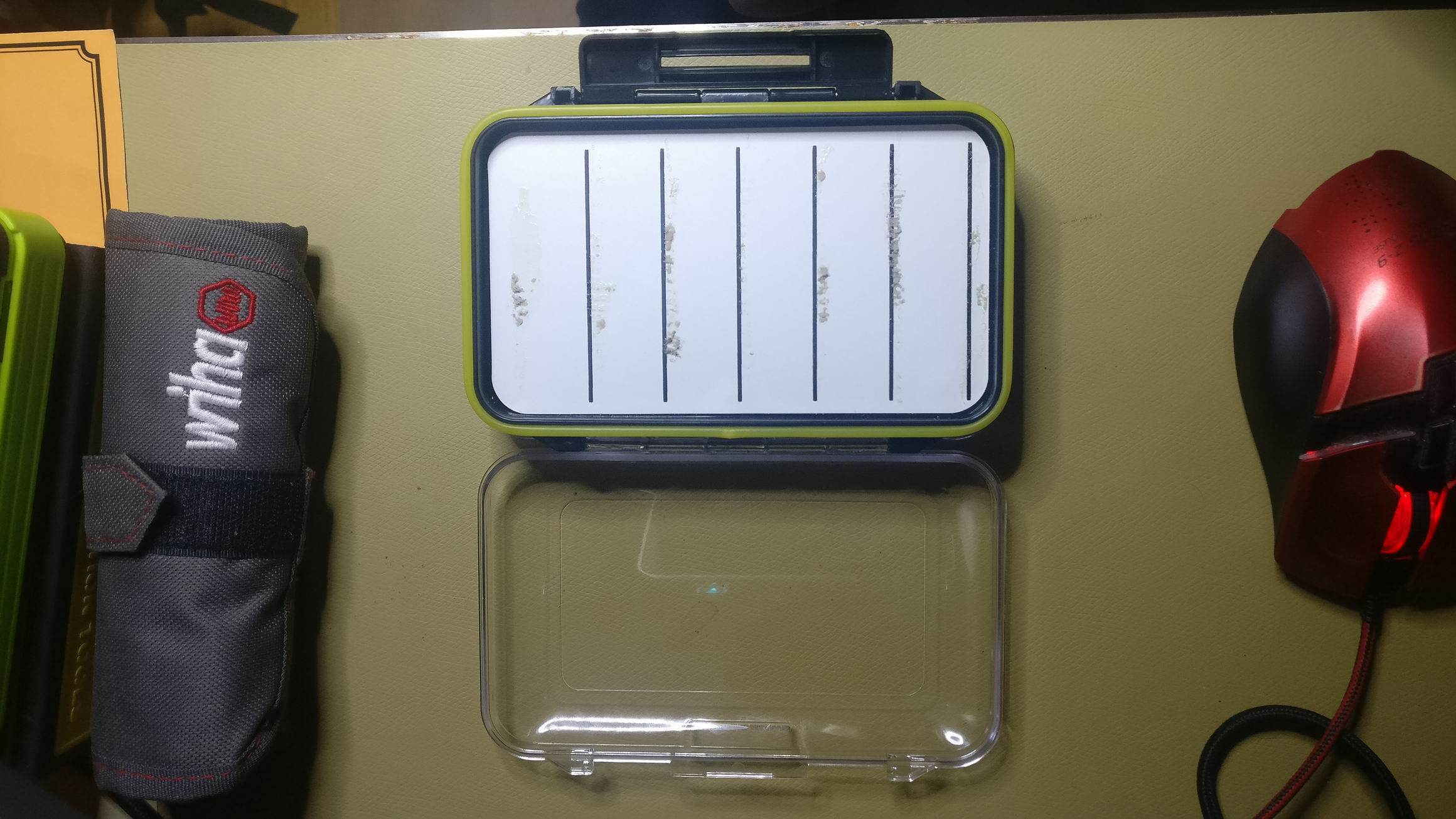
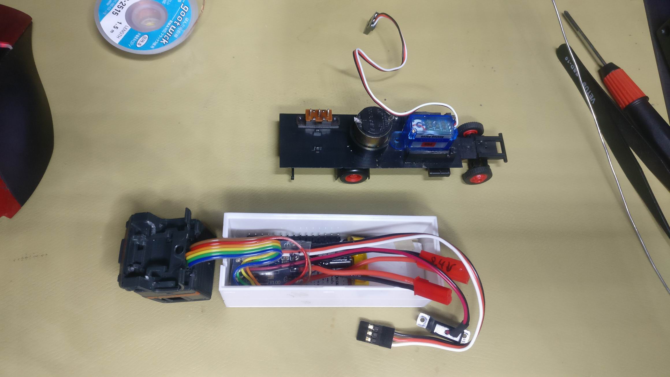
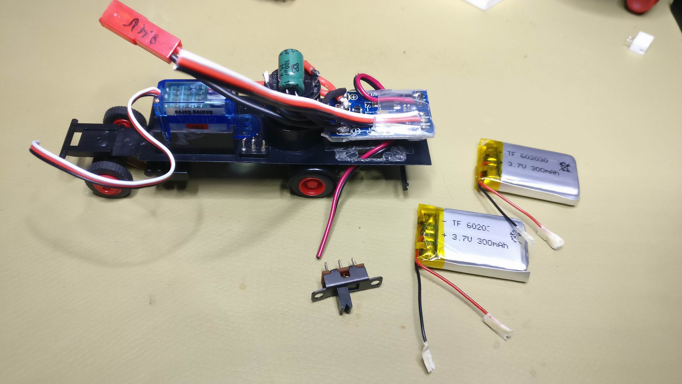
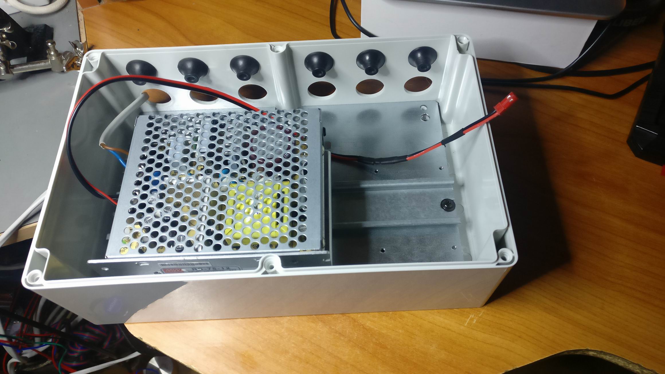
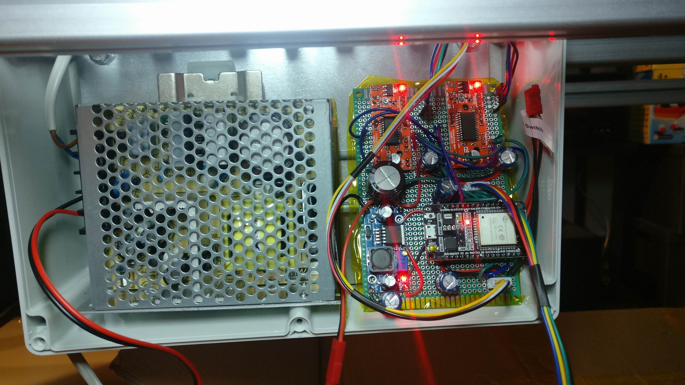
The case is a rats nest
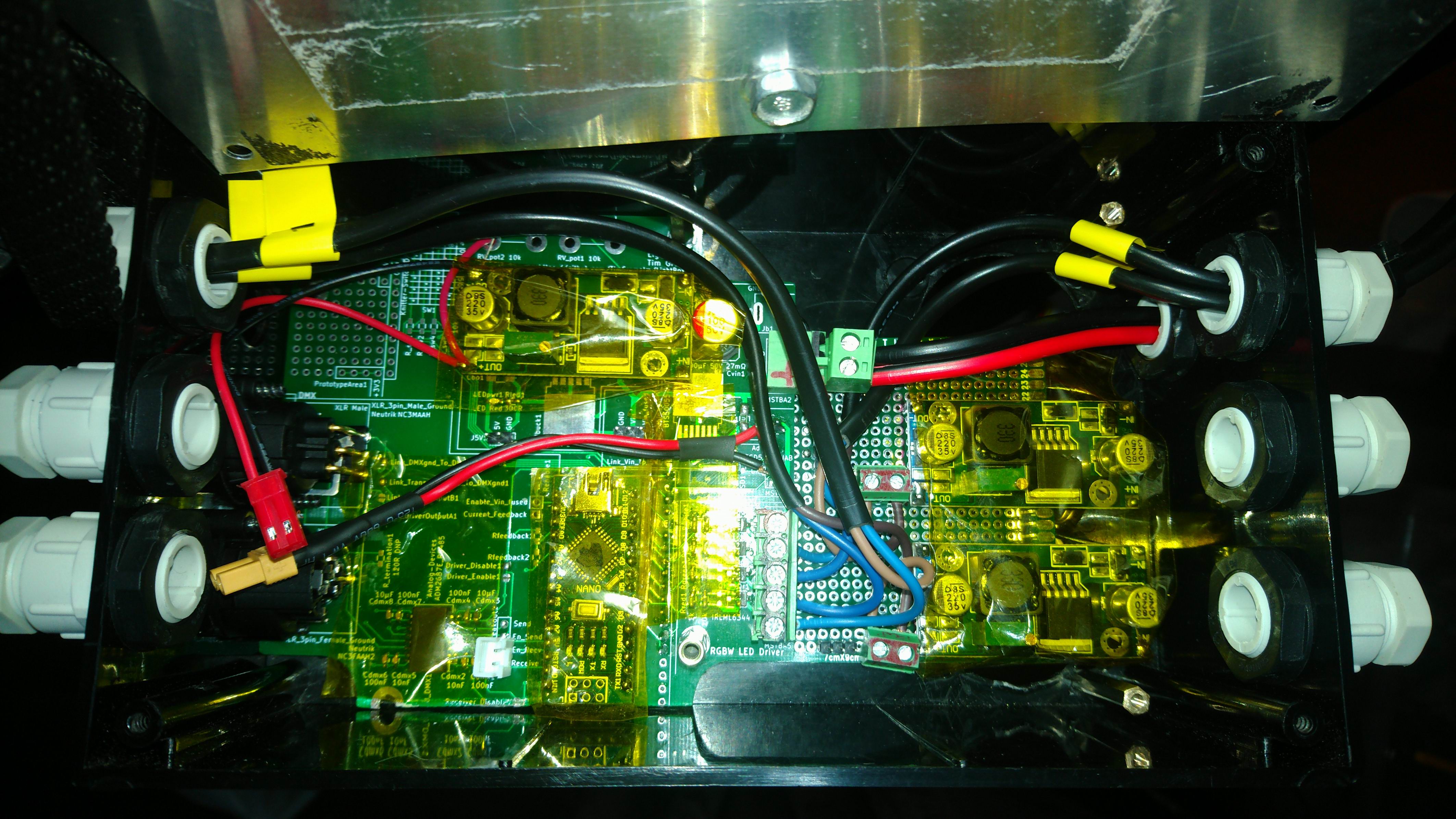
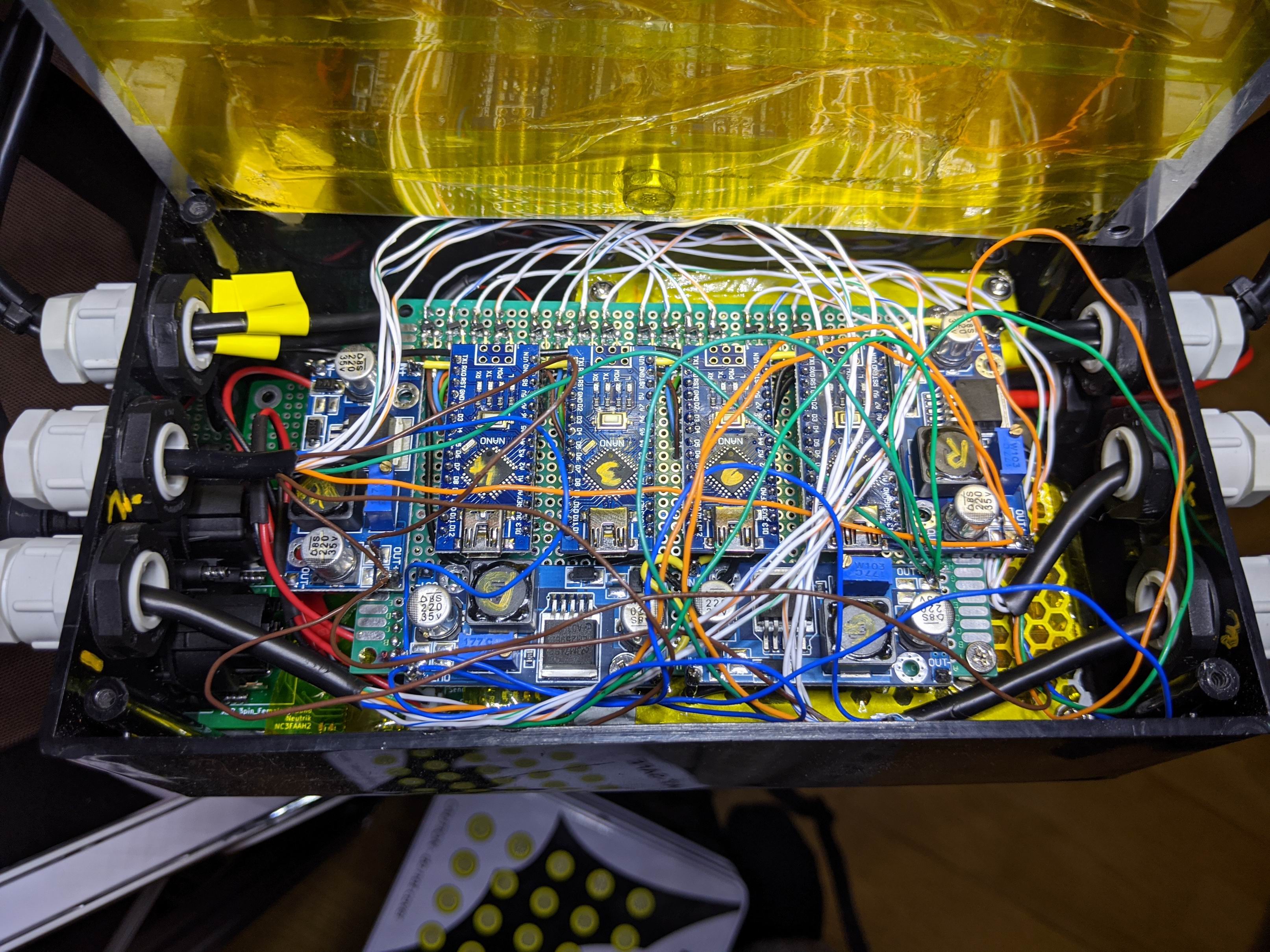
Power input, DMX, 4 cables to the COB LED’s and 4 ethernet cables with 4 pairs each goeas in to one case.
The mess is real.
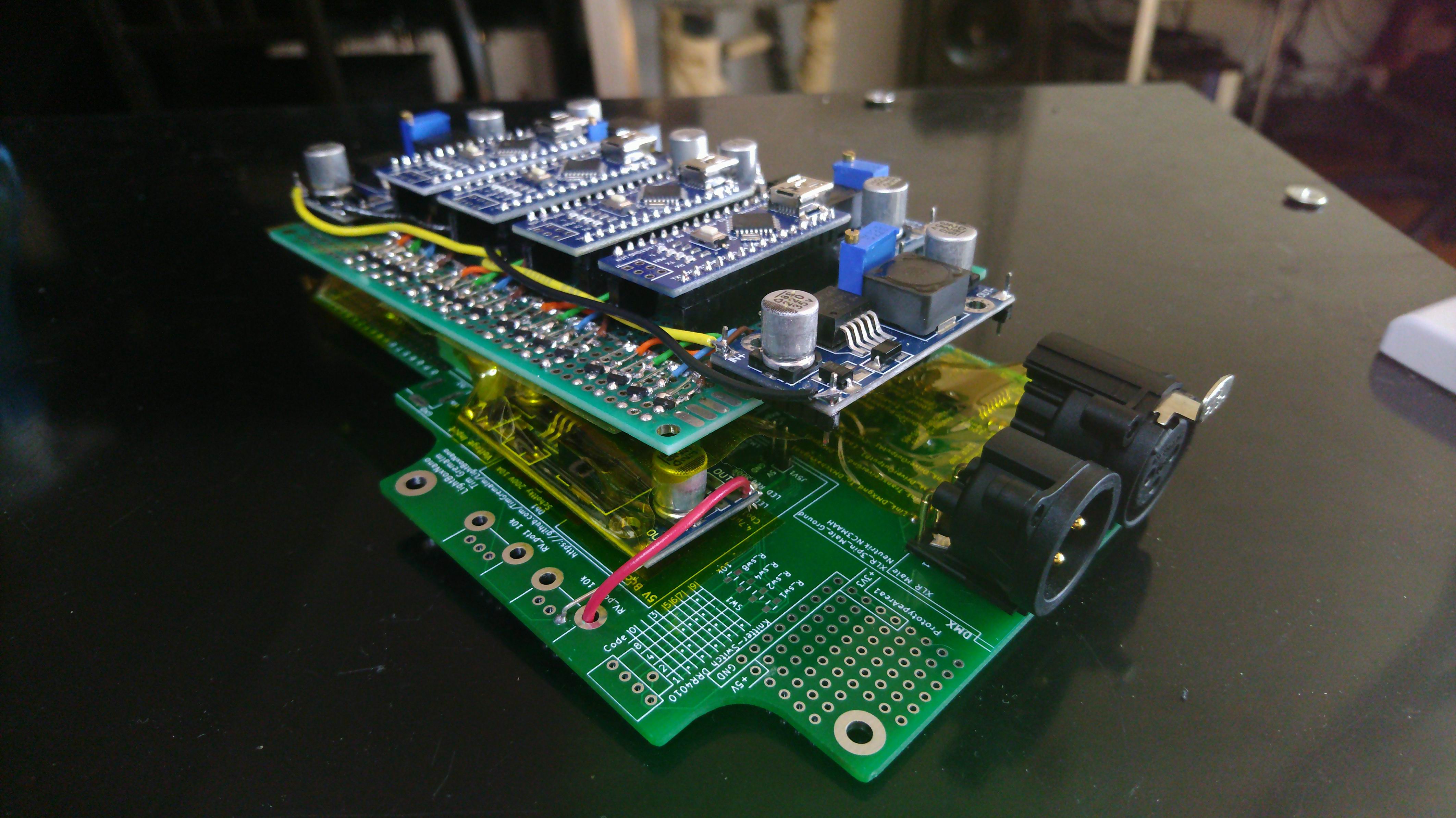
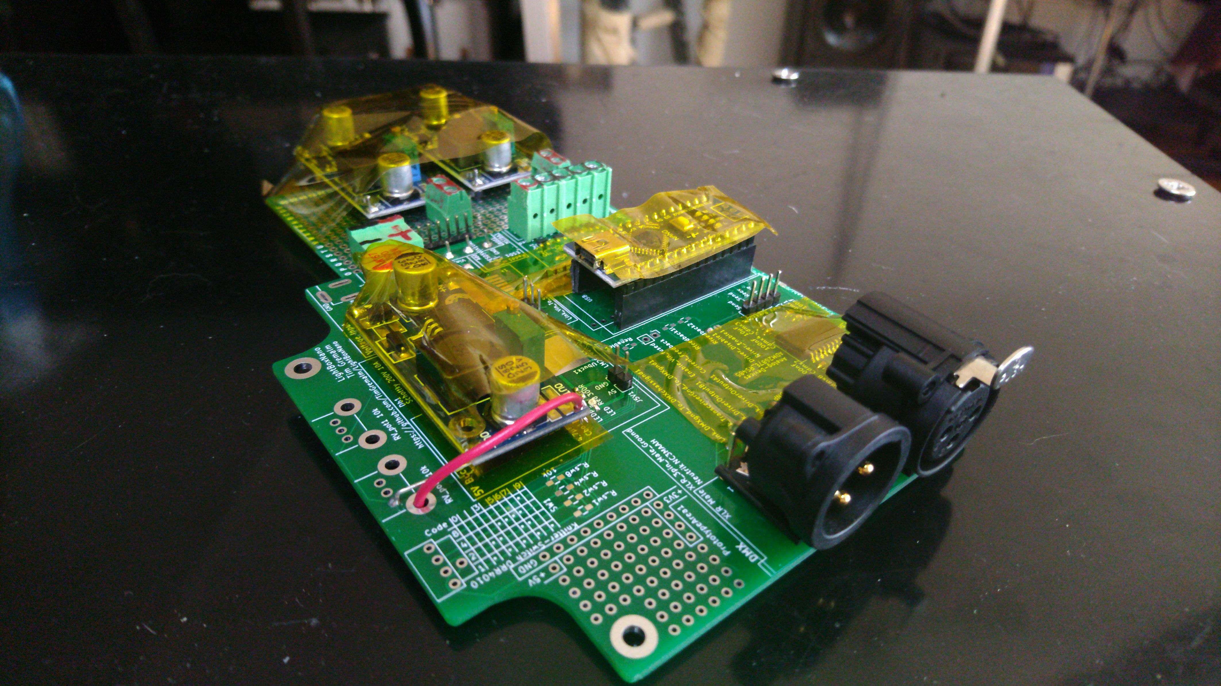
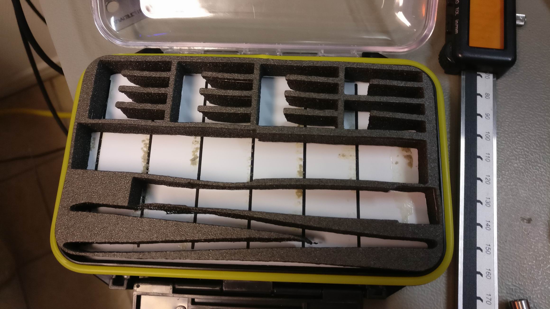
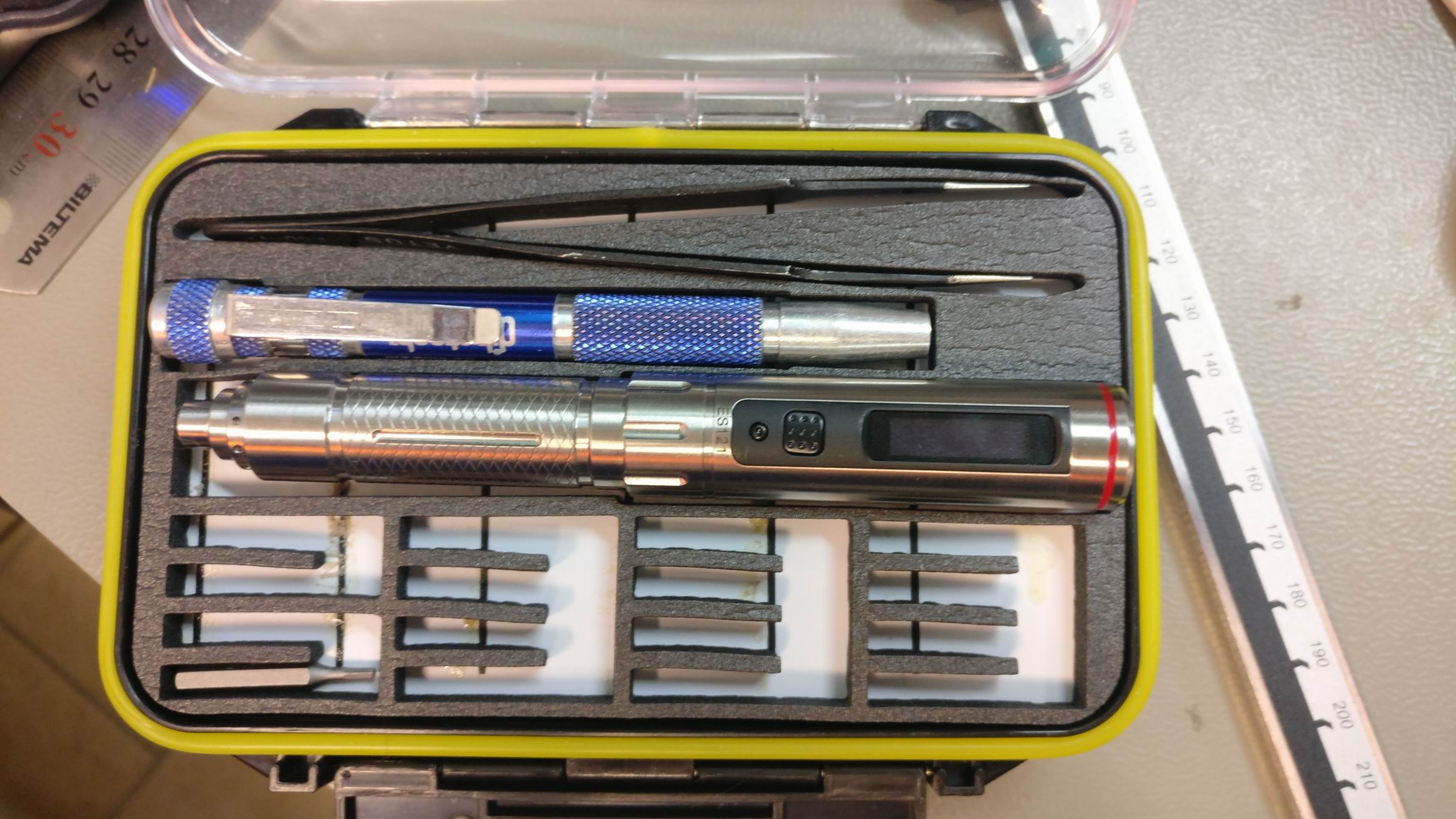
The two LED drivers stack.
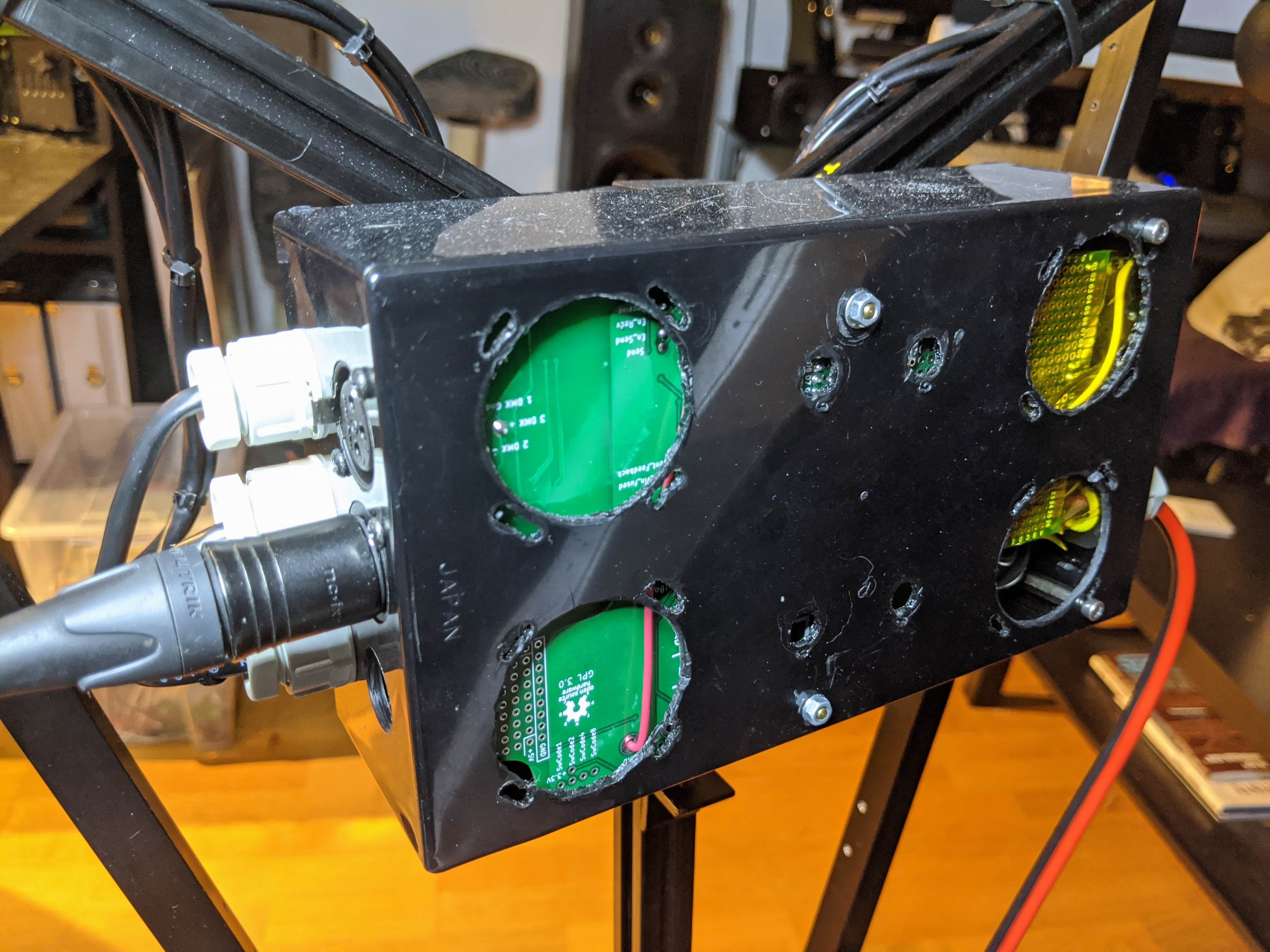

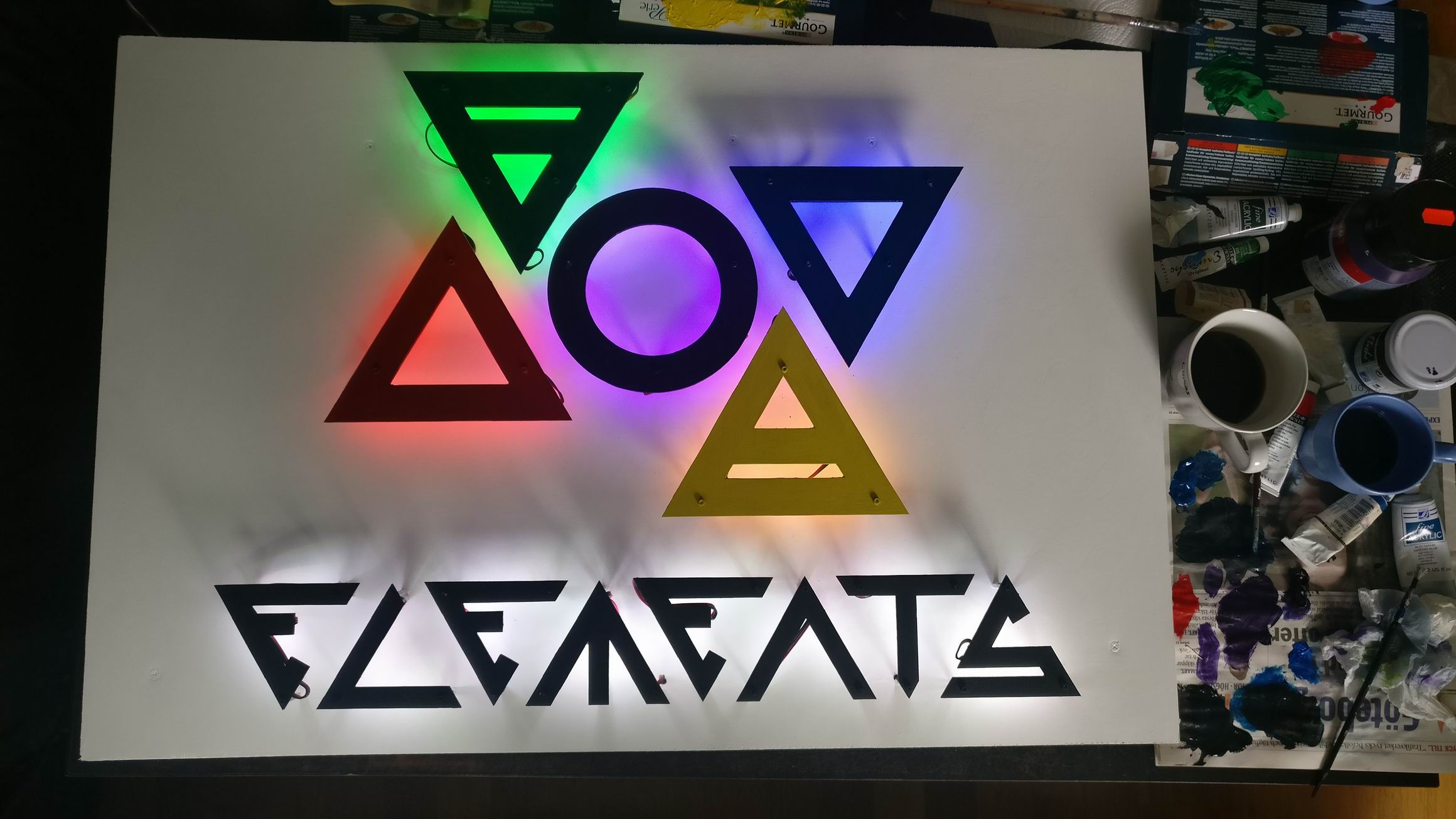
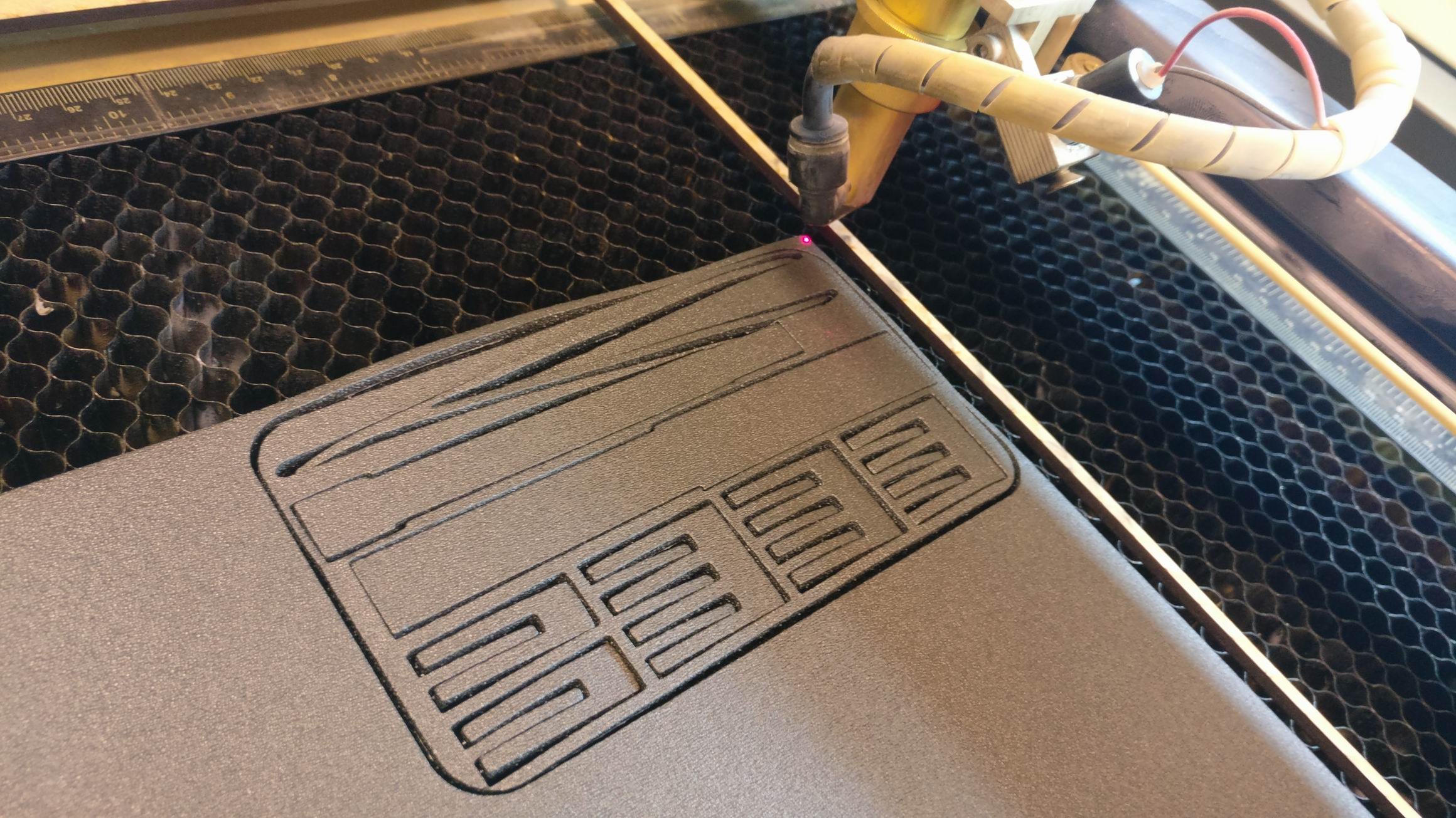
I used an older case for the LED drivers, the size was perfect but i got a lot of old holes. I’ve to find a cover for this. Maybe I’ll put a “Ljusmaskinen” logo here in the future to cover up the ugly parts.
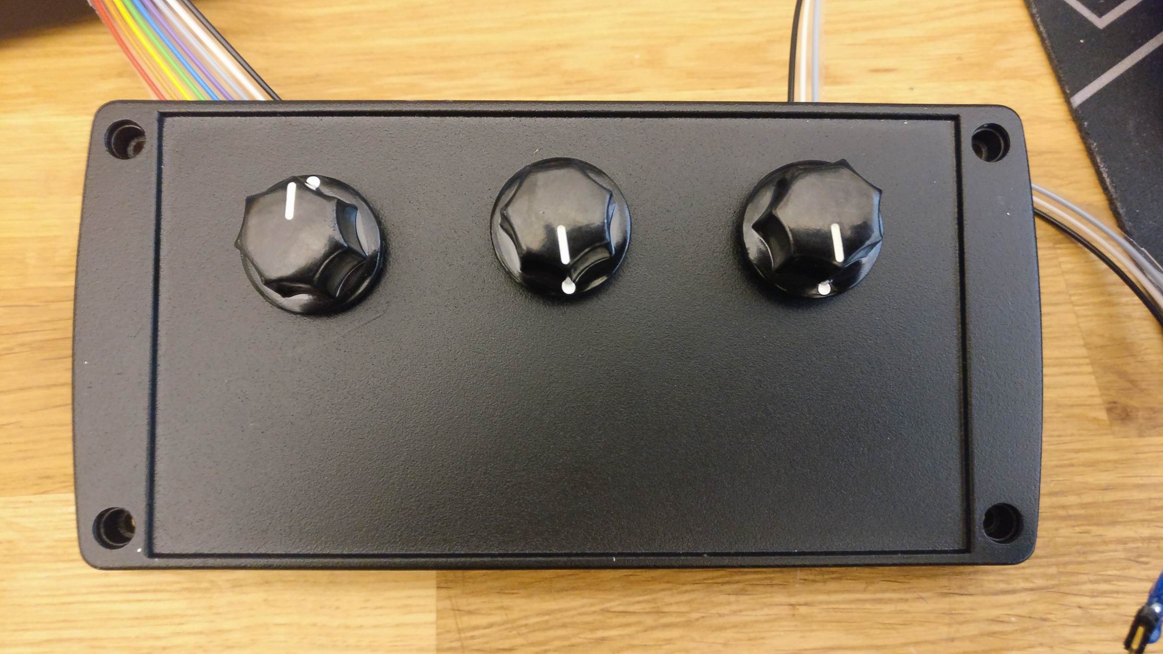
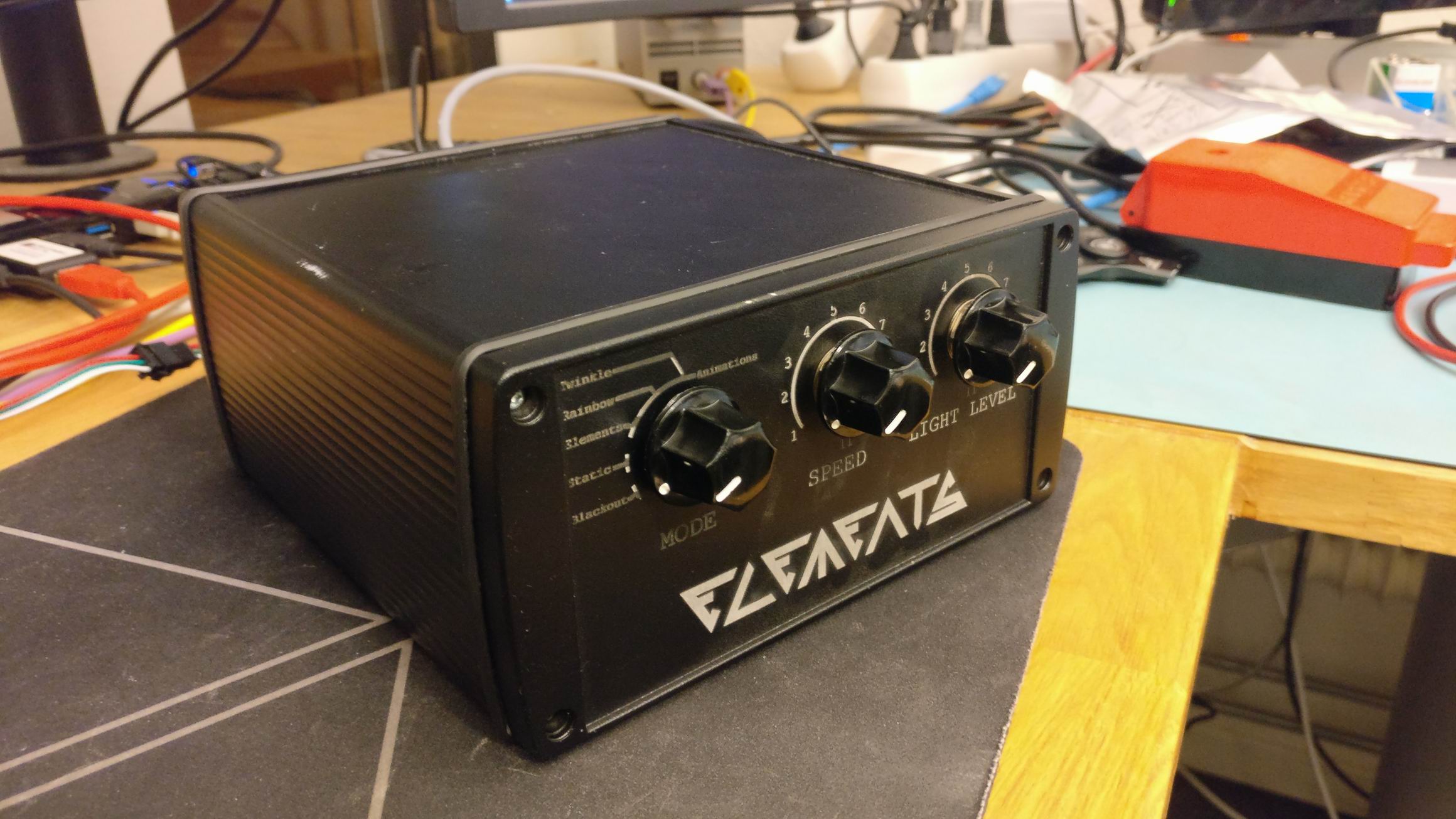
Light Controller
I could have written some software for the MCU to run the lights, but that would make it hard to control and change in the future. Therefore I decided early on to use QLC+ for controlling the lights. It’s an awesome software that holds a professional grade for scene lighting. It’s also free, free as in freedom.
Using QLC+ I could program the lights easy and achieve total dynamic control.
But I needed a computer for running the software. I thought of a laptop, but the cable mess and potentially glitching DMX dongles in the backpack freaked me out.
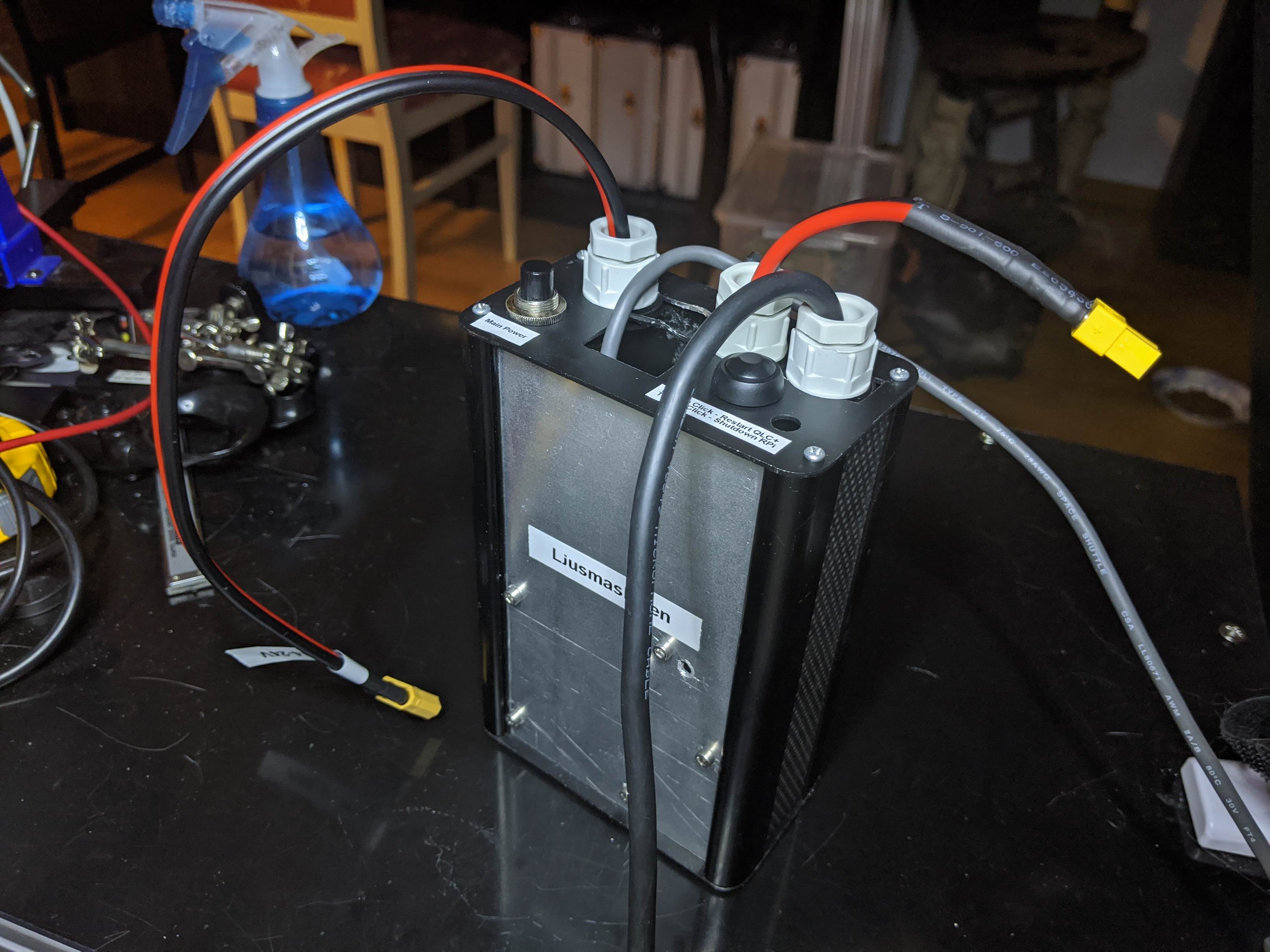
I decided to use a Raspberry Pi, that way I could mount everything in a case and it would use very little power compared to a laptop.
A laptop will still be used for configuring QLC+, but at runtime it would be completely standalone.
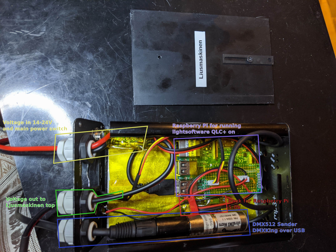
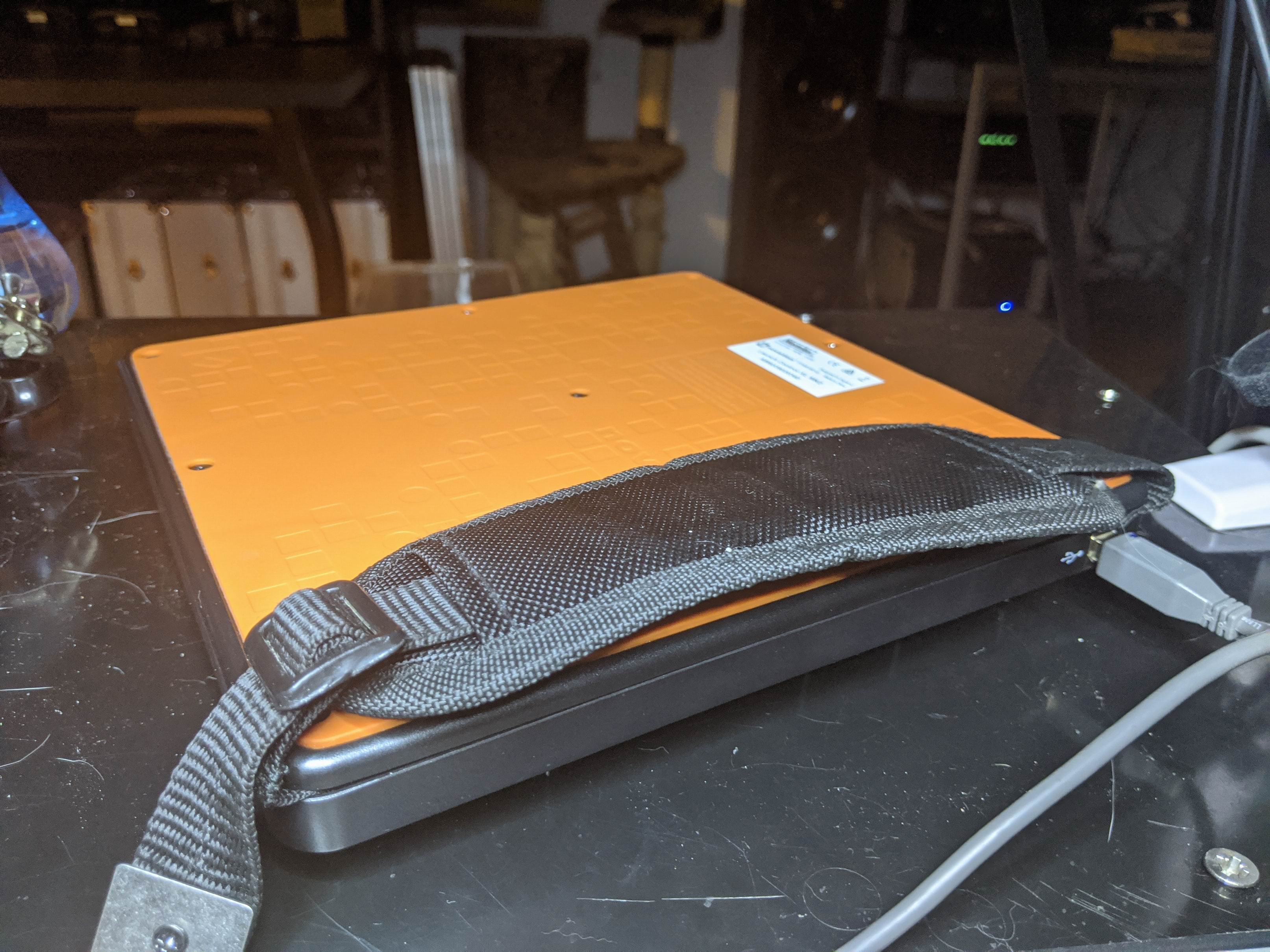
The case holds a Raspberry Pi, a small buck converter to lower the input voltage to 5V and a DMX King USB dongle.
It also has a main power switch for cutting the power.
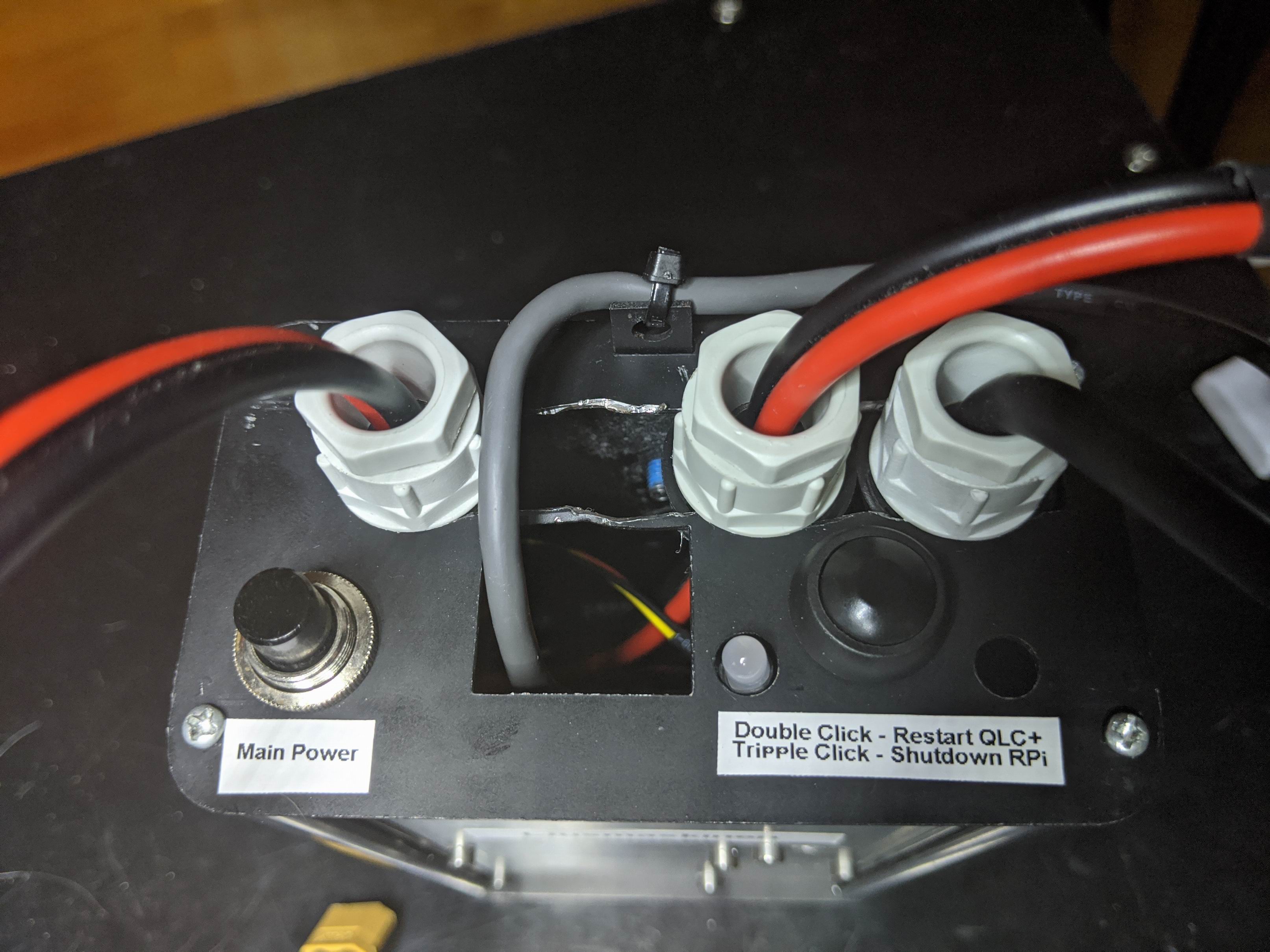
I’ve also attached a button and a two color LED as interface. Since I’m going to use a MIDI controller as input the USB connector can possibly glitch and then the QLC+program could potentially act up.
So a small Python script is listening for double click and triple click on the button and shows the status on the two color LED.
Double click will restart QLC+ and make all USB devices initialize.
Triple click will make a safe shutdown to the Raspberry Pi which avoids a corrupt SD card.
MIDI interface for controlling light
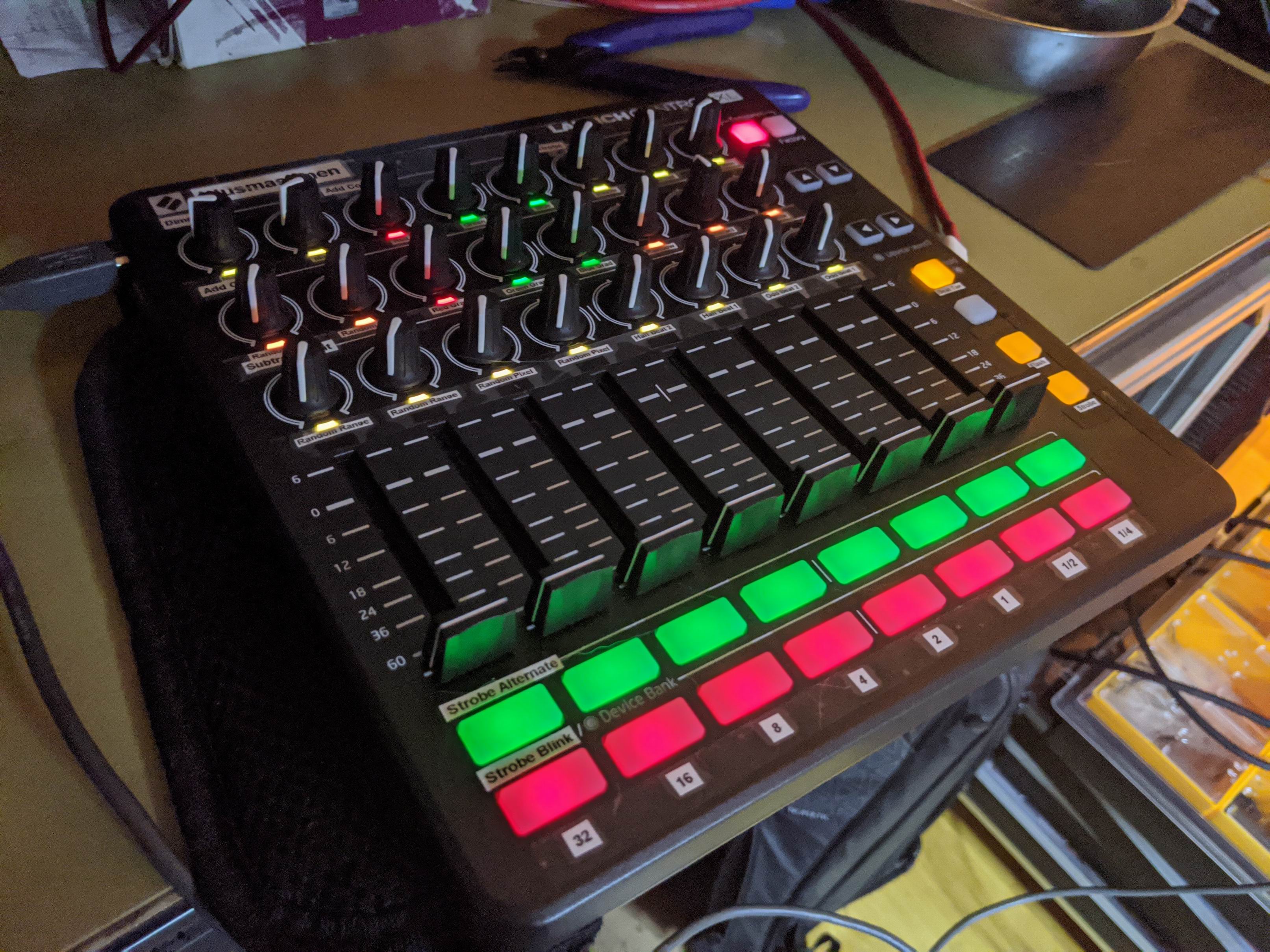
I usually control my light setups in QLC+ over OSC (Open Sound Control) over UDP. But a friend of mine use a MIDI controller and it makes the timing and control so much better. So I decided to invest in a Novation Launch Control XL.
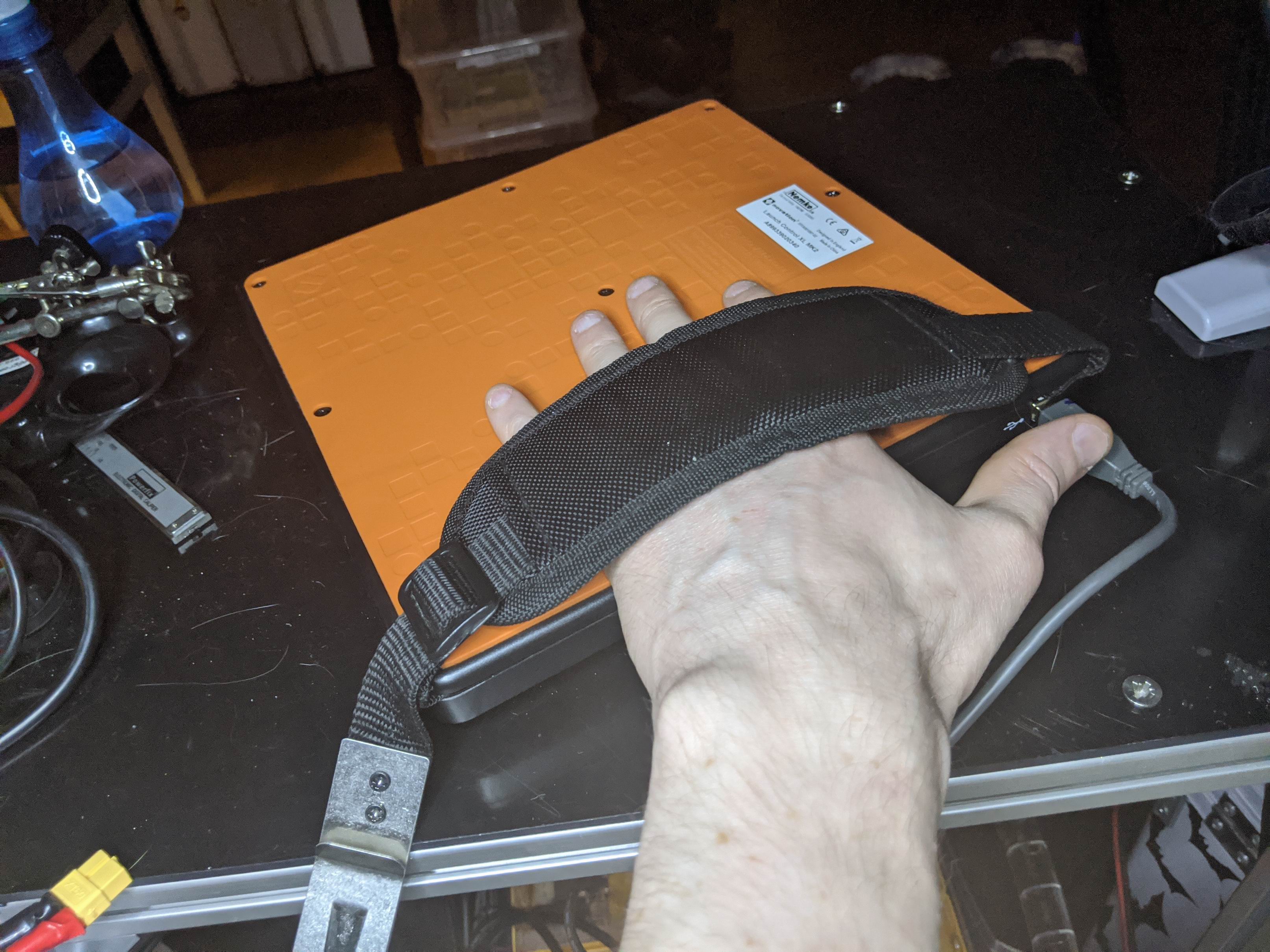
But holding this big 239x239mm wide beast with one hand is hard. So I mounted a mount for my hand, this way I can hold the MIDI controller with one hand and adjust the knobs with the other.
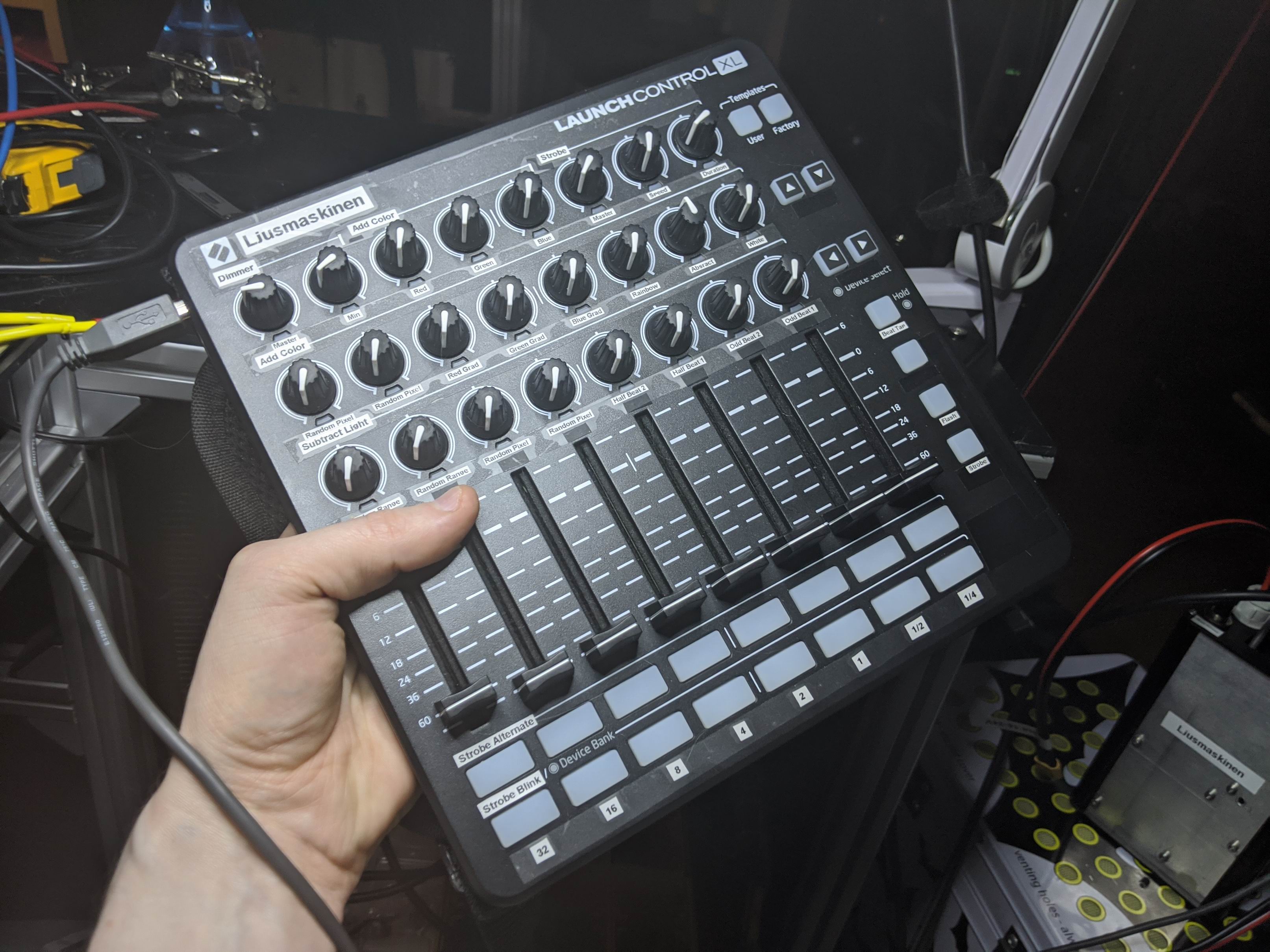
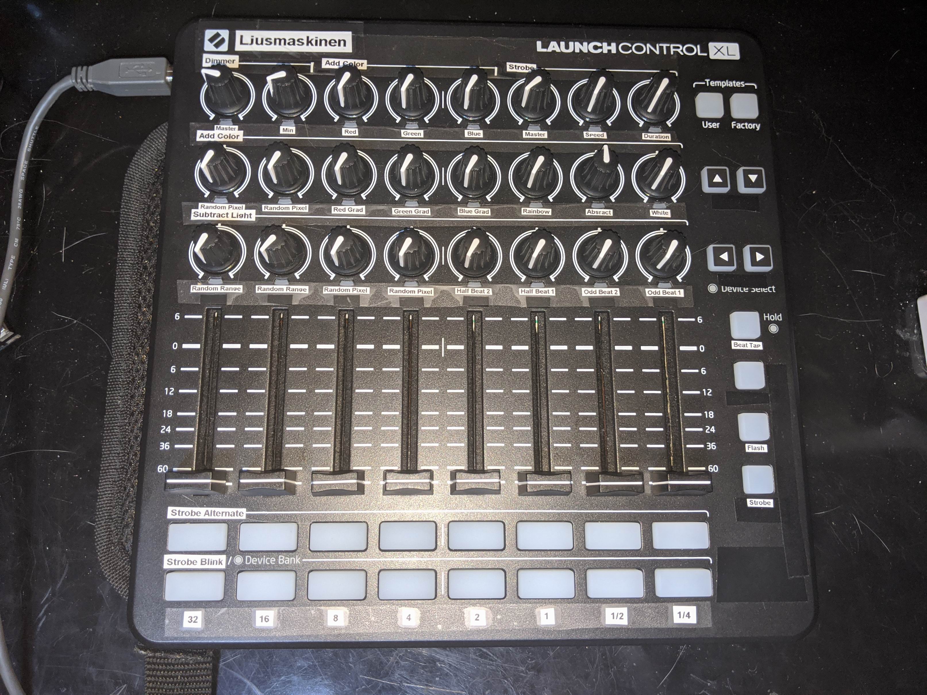
Light controlling layout
To build a good light program is hard, especially when you want to build dynamic light patterns and have the ability to change them to music in real time.
A friend have taught me a new way of working with light programs and it gives so much dynamic control. It’s hard to explain in words, but you kind of working with colors and brightness separately. I kind of had this workflow earlier, but this is taking it to the next level.
My layout consists of a simple master dimmer for the par spots and another master dimmer for the blinders.
The main feature is pulses that can pulse to quarter, half , every, double, quadruple beat. The slider sets the level of corresponding beat.
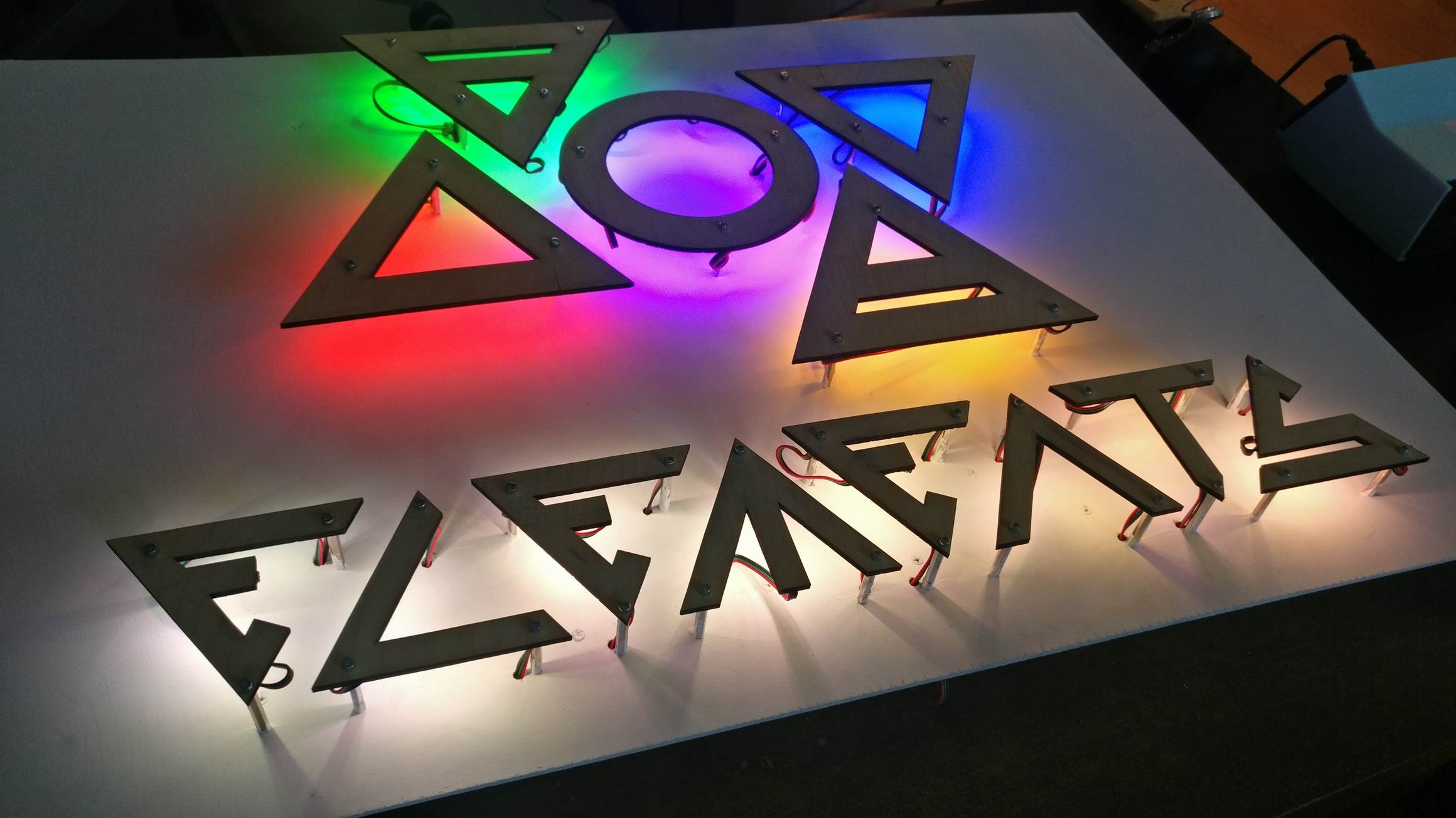
Then I have a “Add Color” section that have standard RGBW fixed colors and a few animated color changes.
The “Subtract Light” section is super interesting! I can black out RGB values in different patterns like odd/even or randomized pixels.
Together it gives me great flexibility to my lighting and I can really express myself to music.
In the bottom row we can find buttons that pulses the blinders to corresponding beat.
To have blinders on all time looks really bright and boring. But I’ve invented a maximum duration setting for my blinders that makes the blinders to be on for a maximum time. Together with the longer flashes of example every 16 beat flash and a maximum duration of 200ms gives some fantastic rhythmic flashes.
Fun Will Now Commence
This was just a mad thought in my head that I acted upon. And I’m glad I did, it was so much fun!
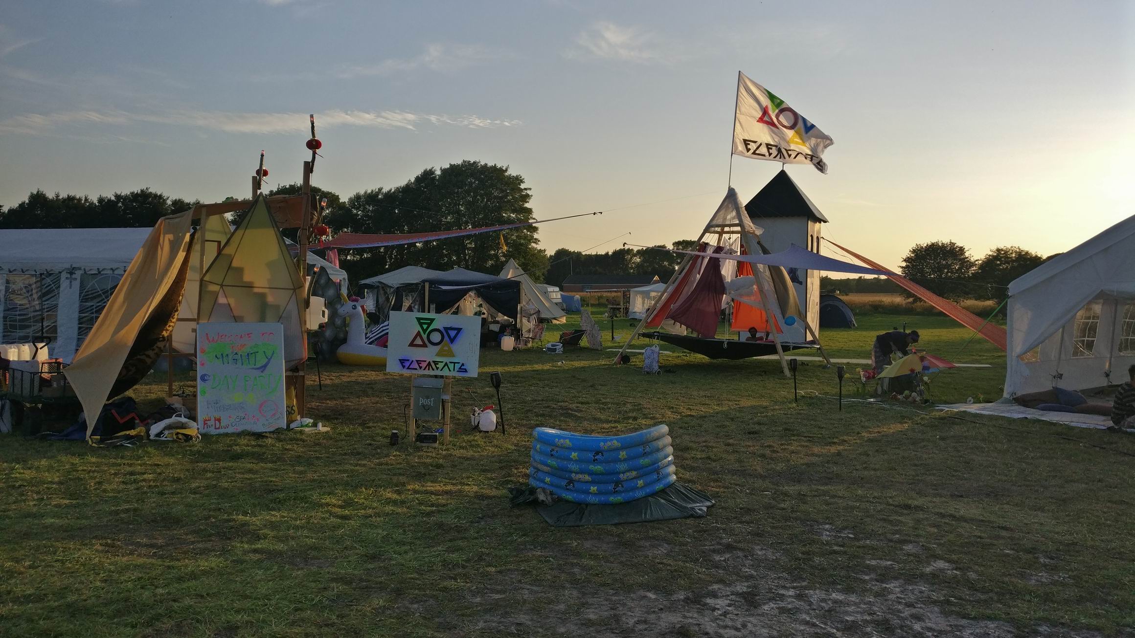
It will really go great together with Festmaskinen, and I’m so hyped about the mobile raves the future holds.


