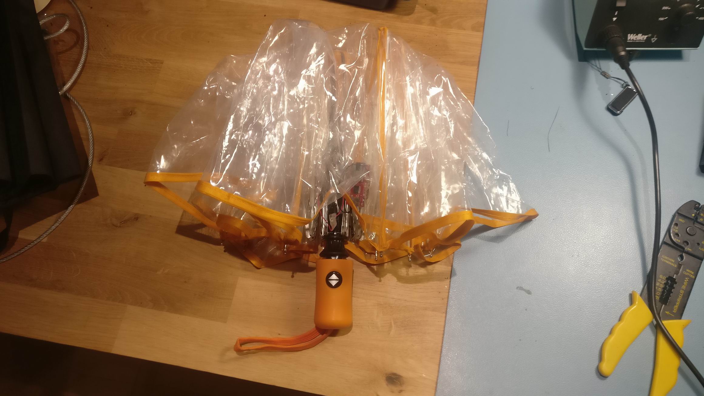
An umbrella that will play rain sound when opened.
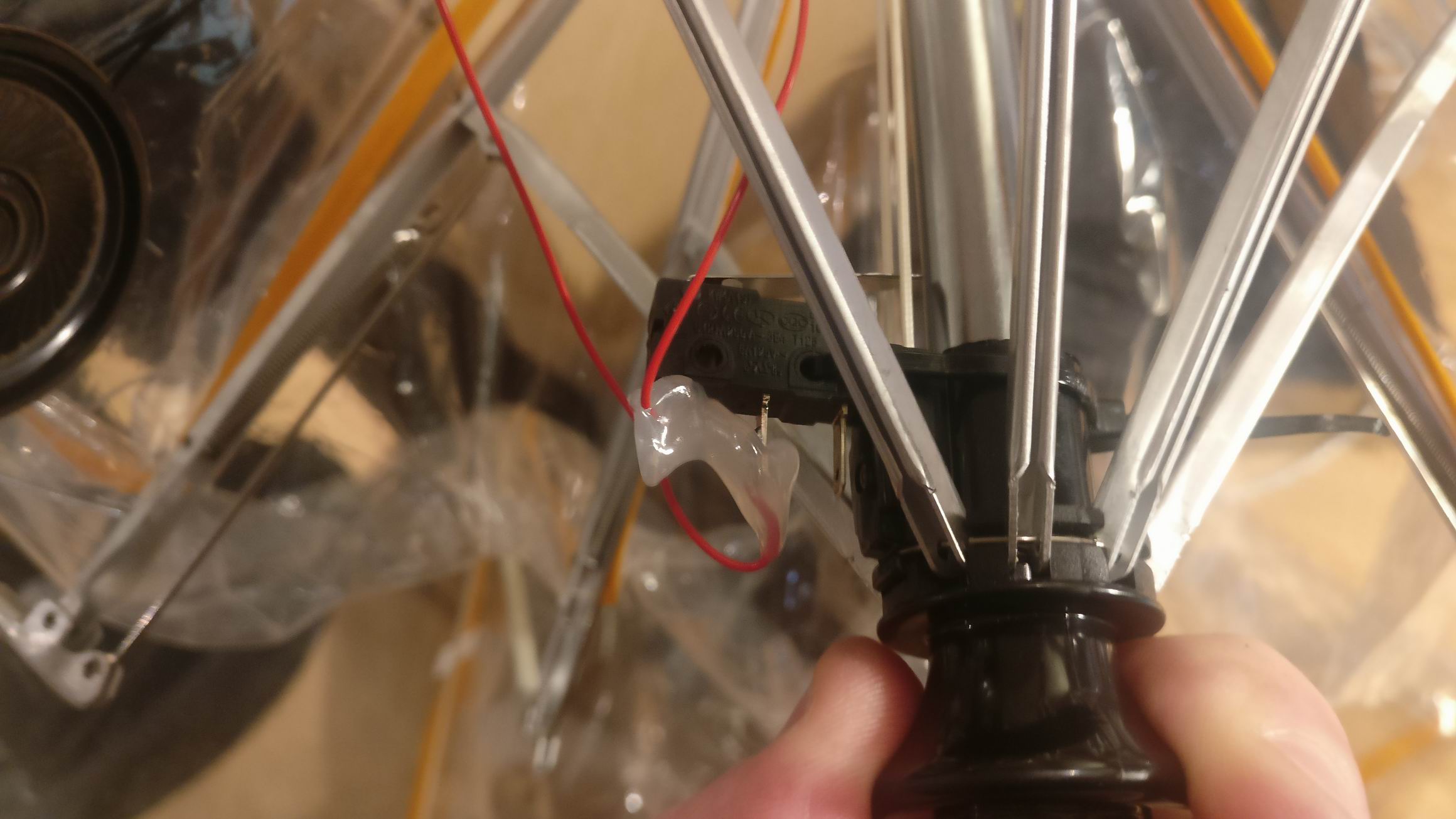
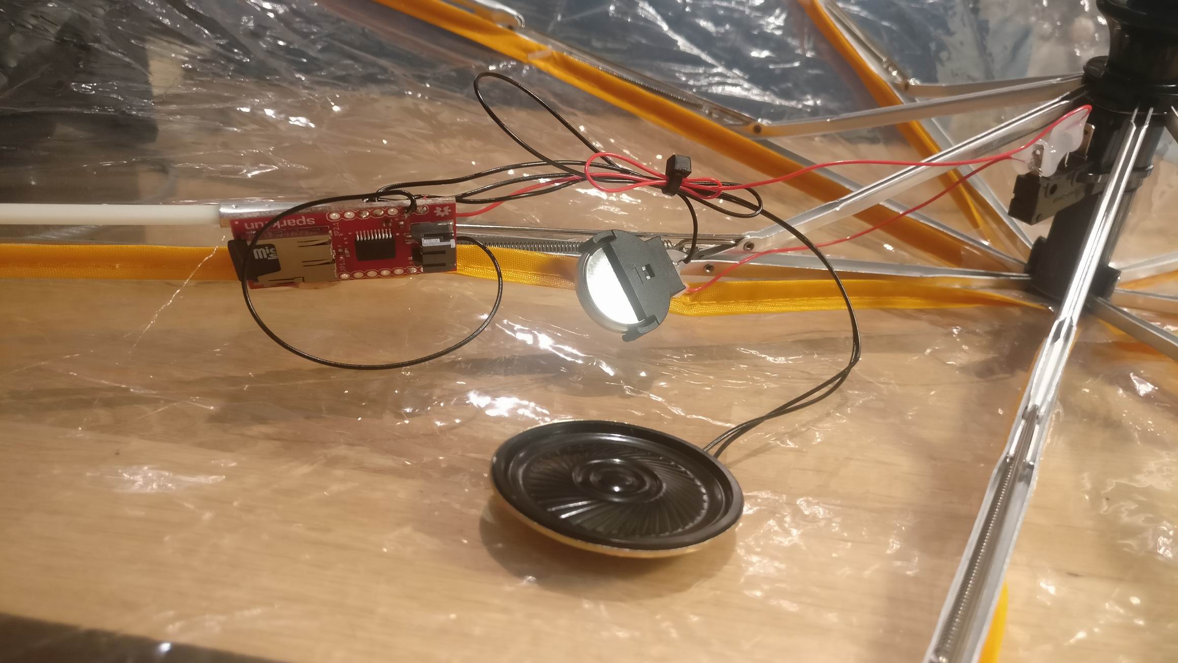
A micro switch will cut the power to an MP3-player module will built in amplifier when it’s folded.
An umbrella that will play rain sound when opened.
A micro switch will cut the power to an MP3-player module will built in amplifier when it’s folded.
I previously made Alco Bong 9000, but it had some flaws. The alcohol chamber was too small and it need some volume to hold more alcoholic mist. It also run on a 6S LiPo battery that was stepped down to 24V.
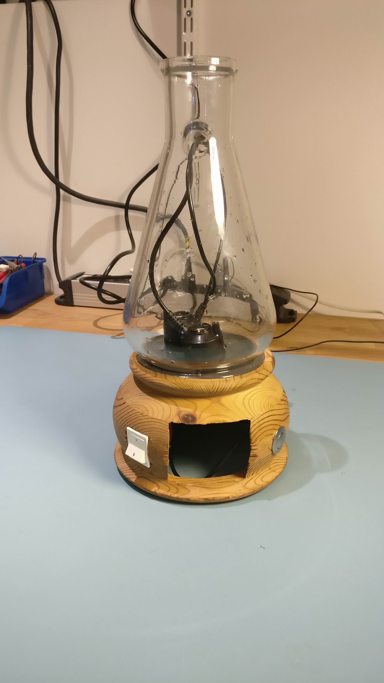
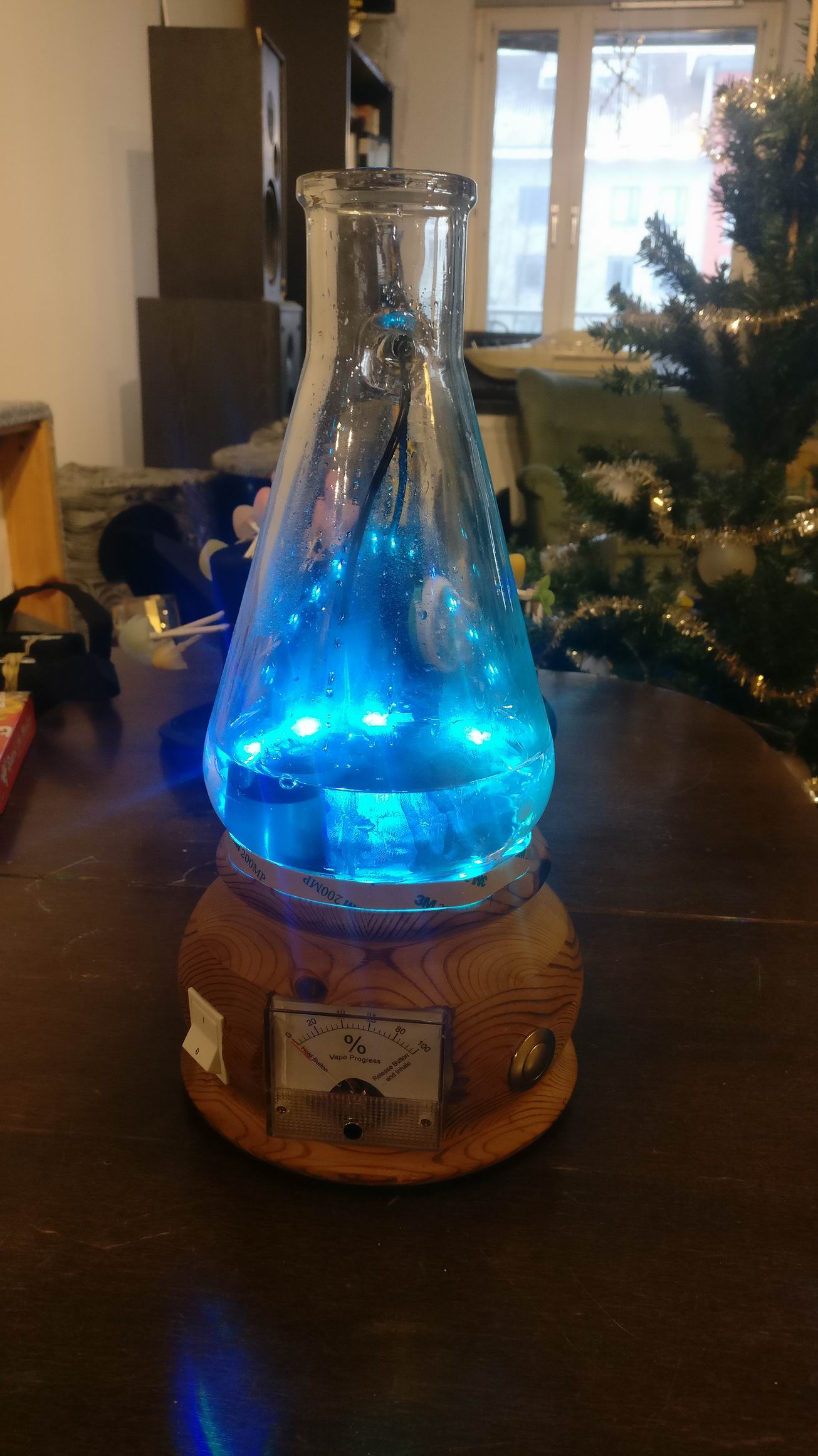
So with the improvements in mind I started out on a new alco bong. I found a big beaker in a second hand shop and started out from that.
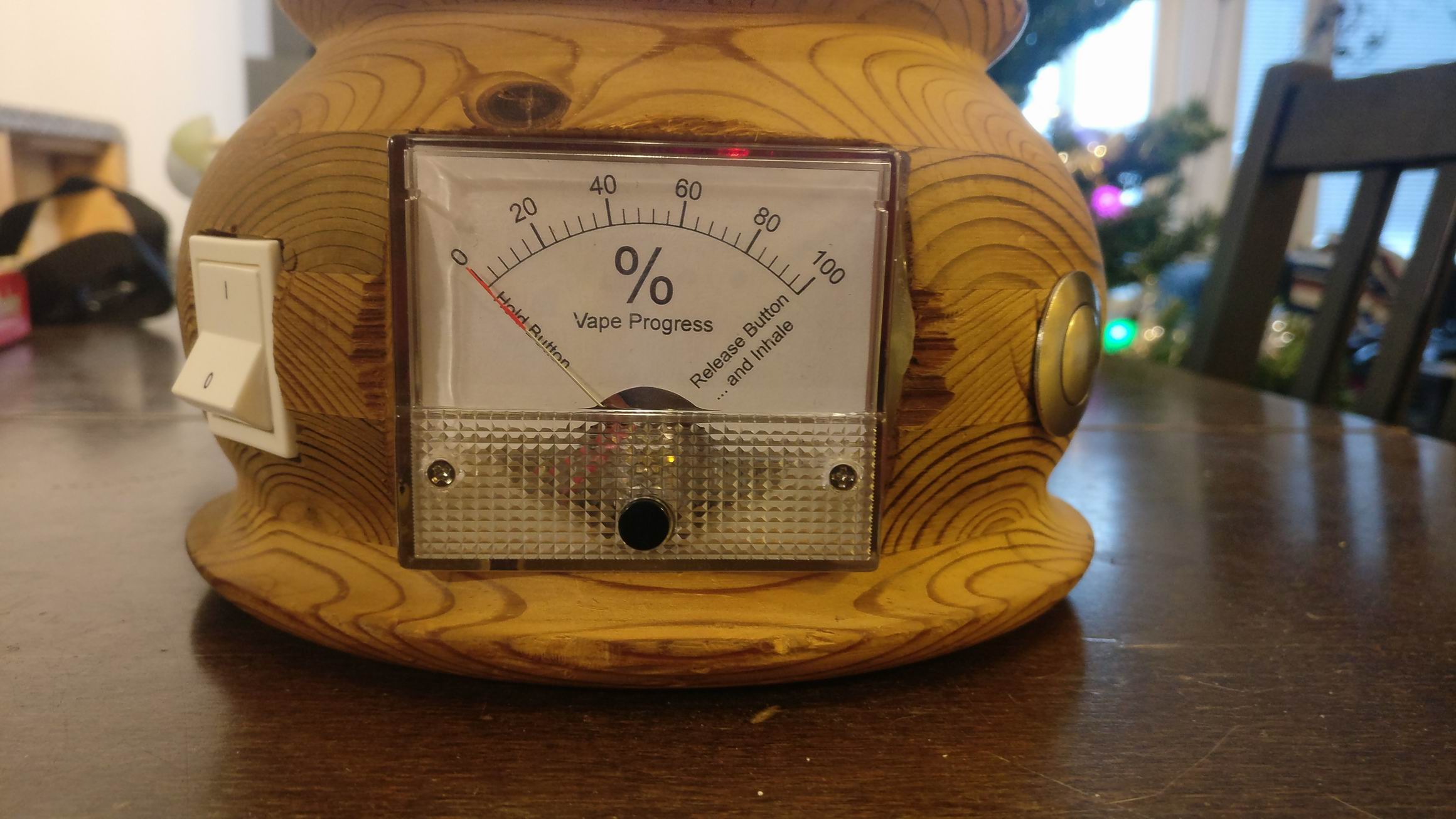
Another problem with the alco bong was that people who used it didn’t understand that they could release the vape-button. So by introducing a progress bar it would be more clear. I installed a analog volt meter and controlling it by PWM.
Because a non-LiPo-knowledgeable person would be using it I installed a battery pack holder using ordinary AA battery.
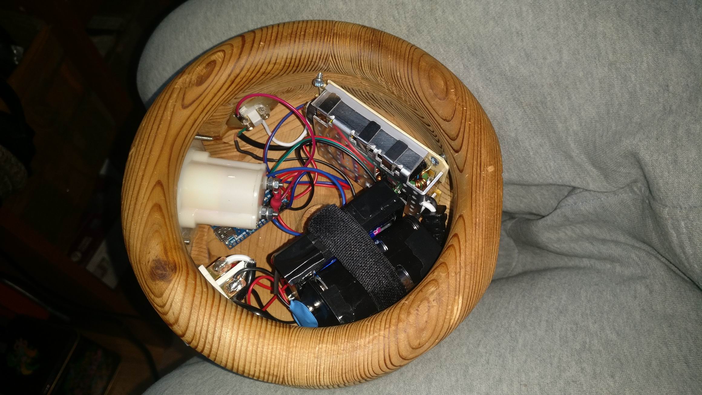
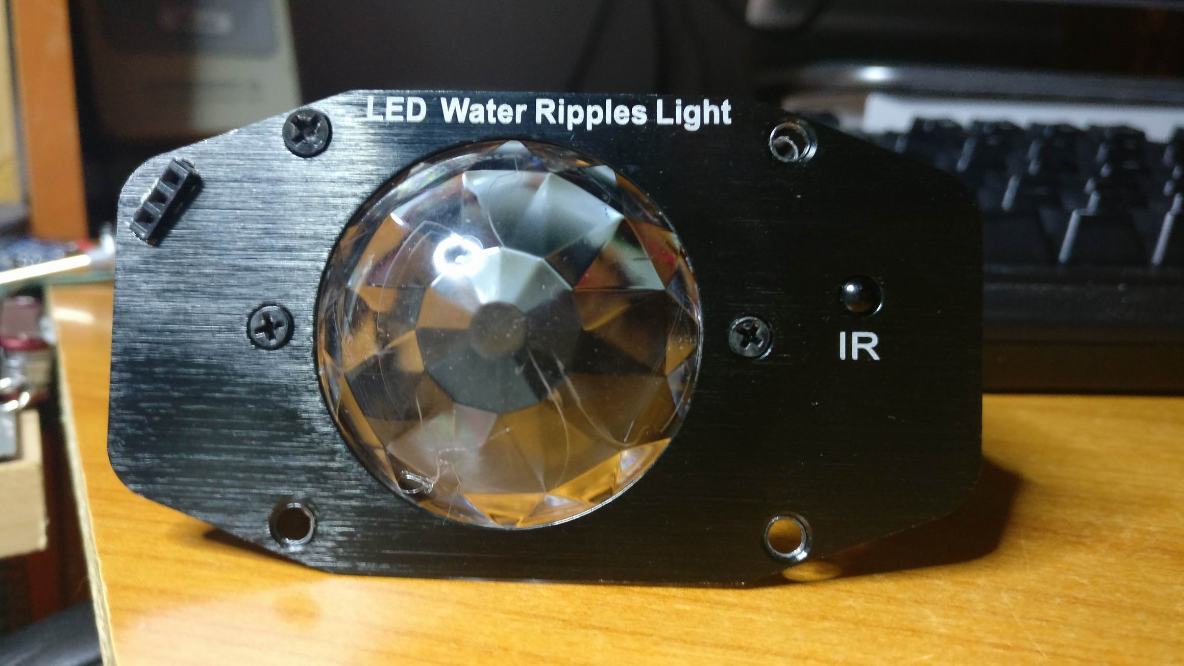
For the larp Do Androids Pray? we wanted to recreate the companys corridor scene from Blade Runner 2049 where some beautiful water light seemed to follow the persons who walked up the stairs.
I thought that it would be doable using multiple water effect light and dim them up when movement was detected.
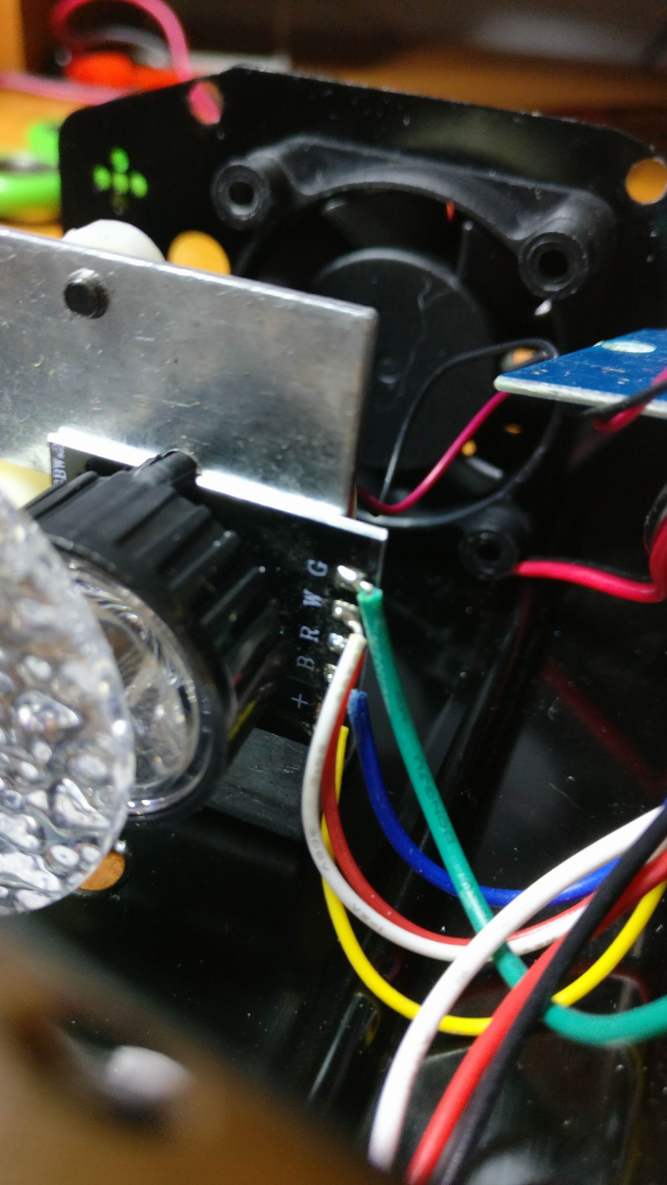
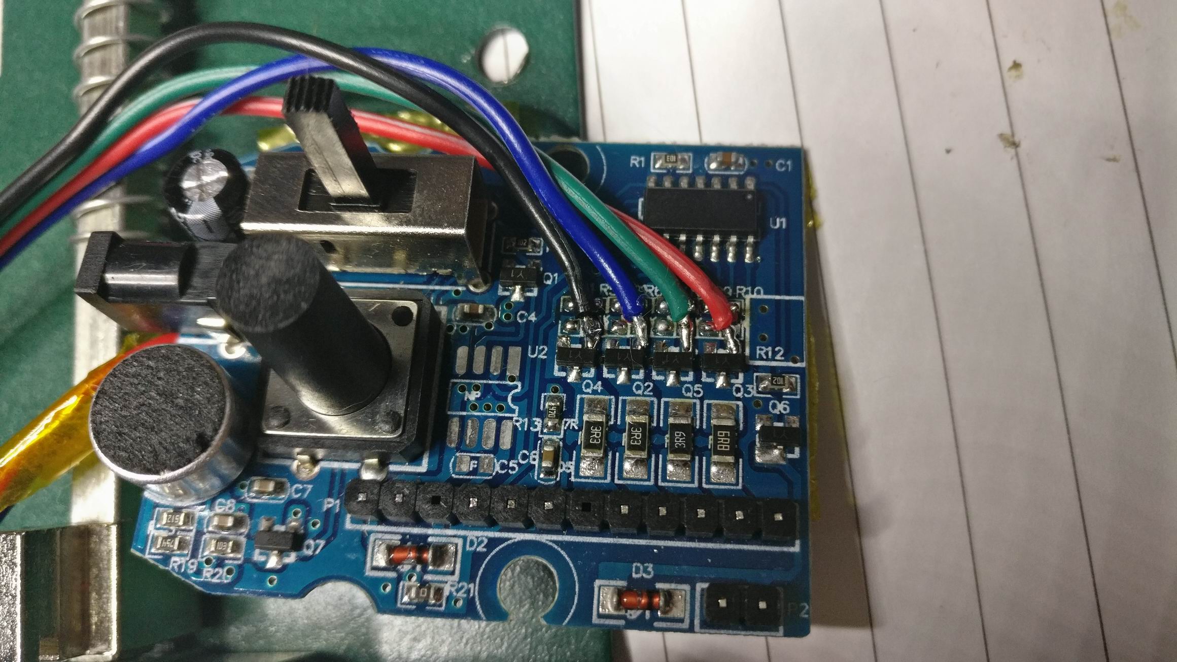
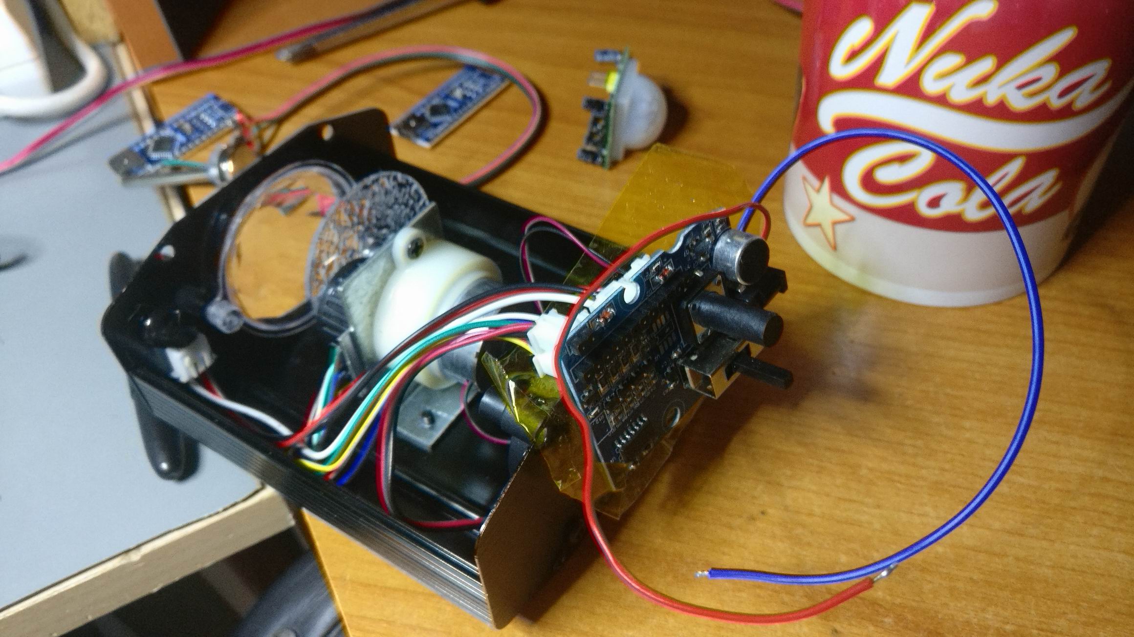
I purchased some cheap water effect lamps of eBay and took them apart to inspect. The LED was hooked up to some mosfets, så I just removed the resistor leading to the original MCU and hotwired some leads to my own MCU.
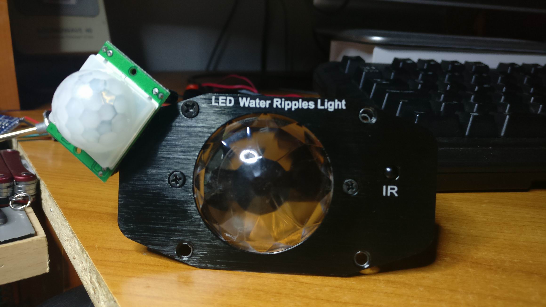
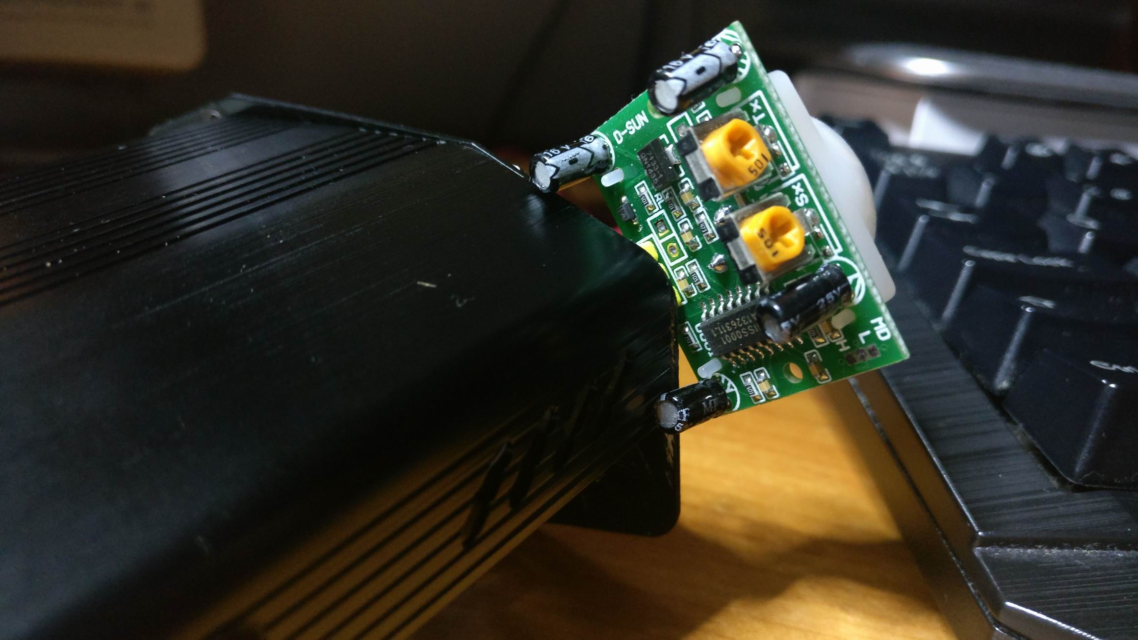
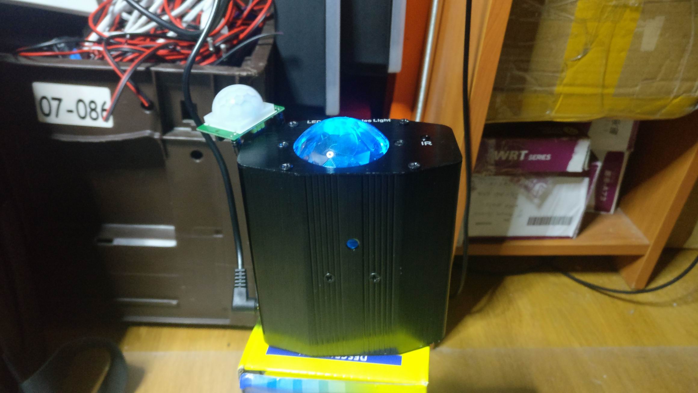
I drilled out a small cut out for a 3 pin header an glued it into place and put a PIR module in.
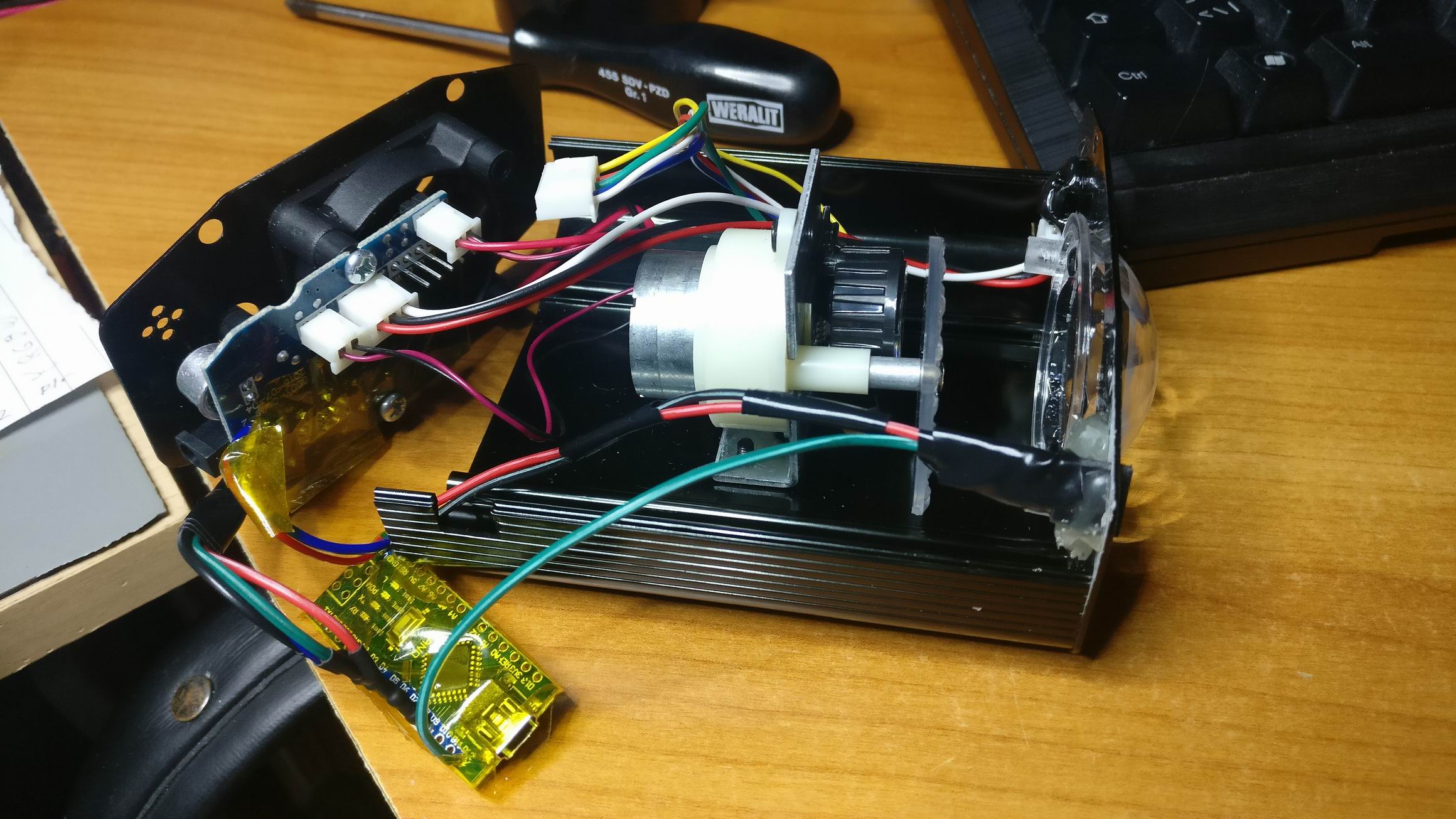
The whole assembly kind of look like it’s original except an exposed PIR module.

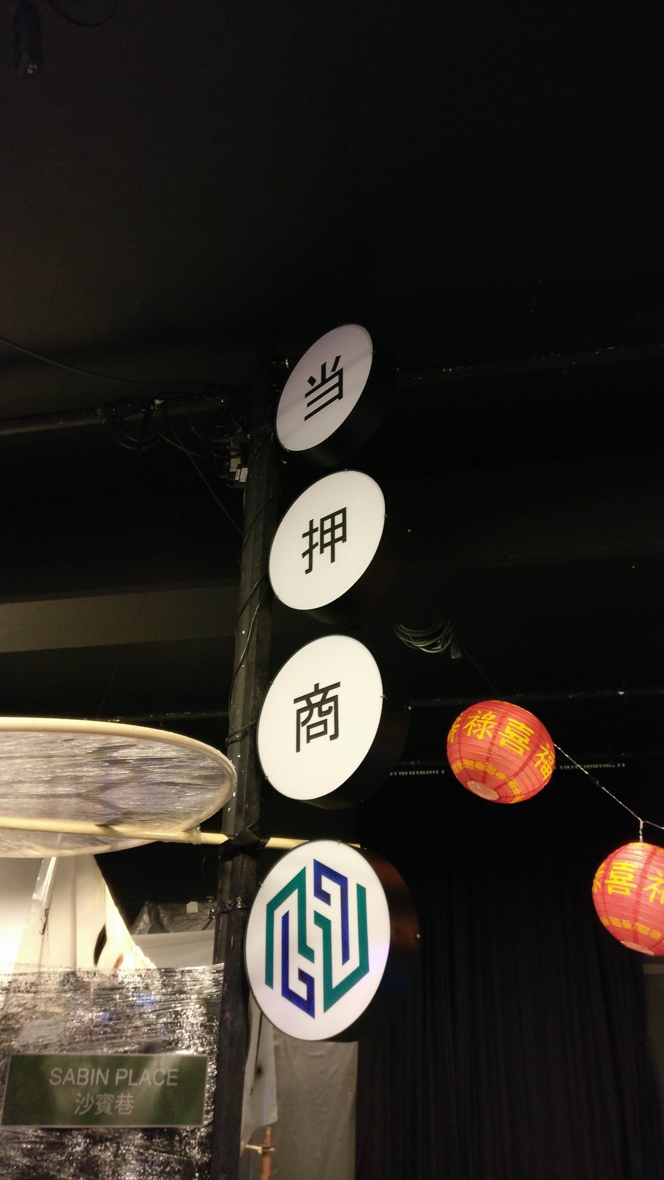
For the larp Do Androids Dream we needed a lot of small props to give a Blade Runner feeling of the scene.
Small lit up signs would give that Hong Kong look that is so common in Blade Runner. Carl Nordblom, the set designer, had some ideas about how the sign should look, and had found some sample pictures.
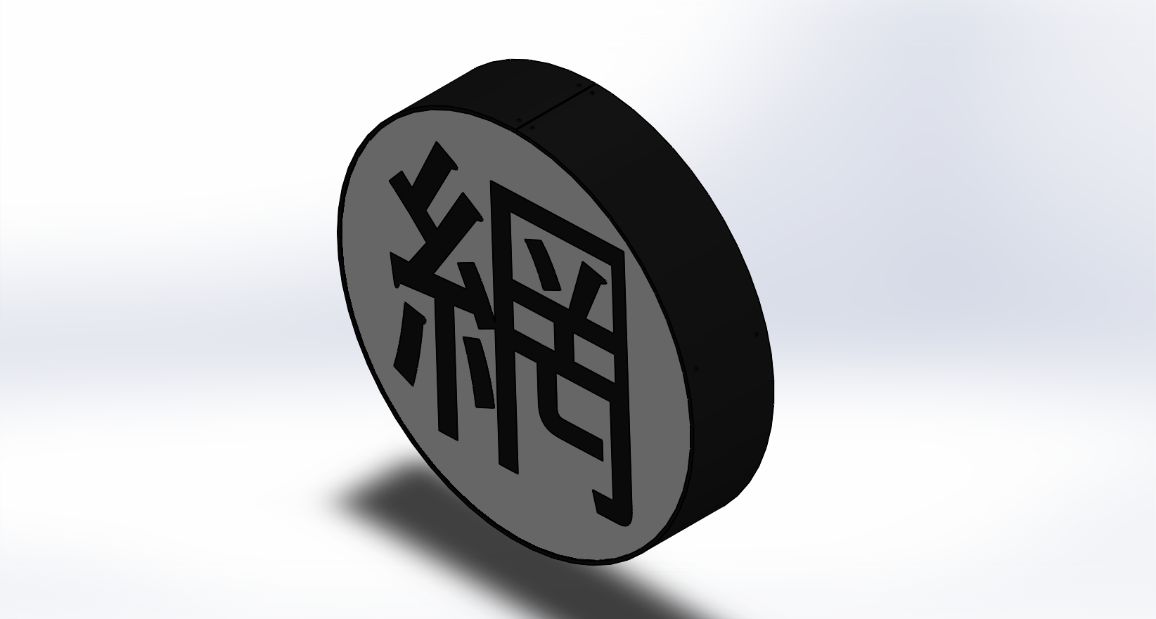
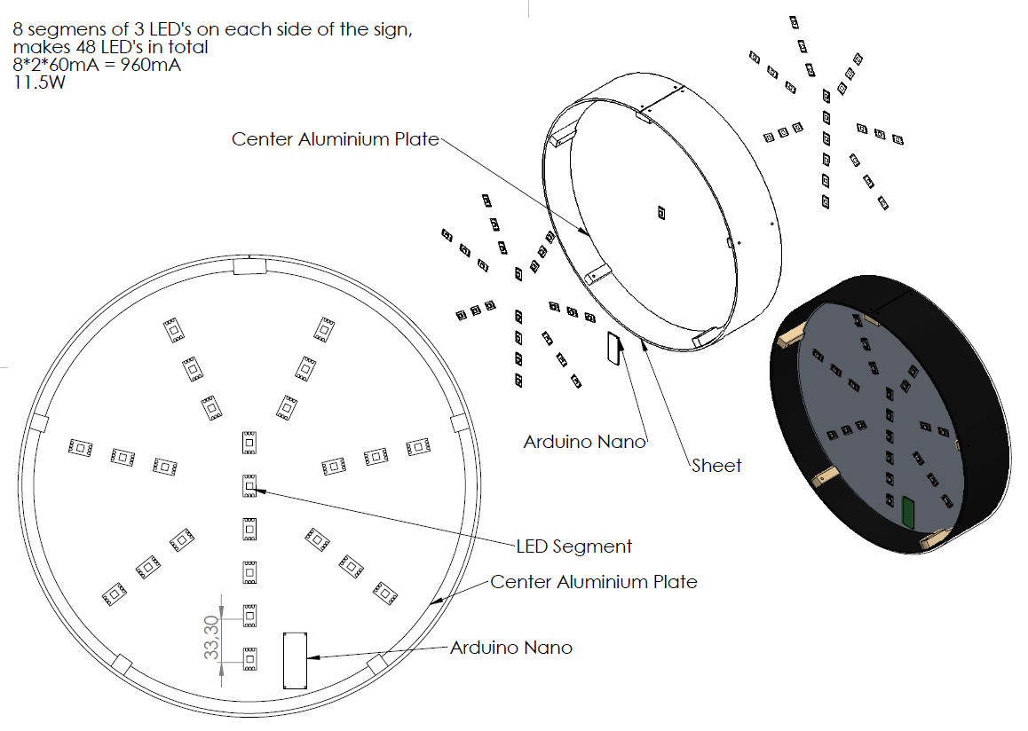
From the sample pictures I got an idea of how to produce a design. And from that idea I started to make a CAD-design.
The finished design ended up being almost exactly like the CAD-design.
Here is the Drawing of the Round Sign (Do Androids Dream).pdf
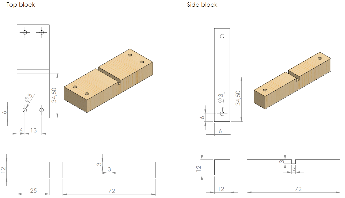
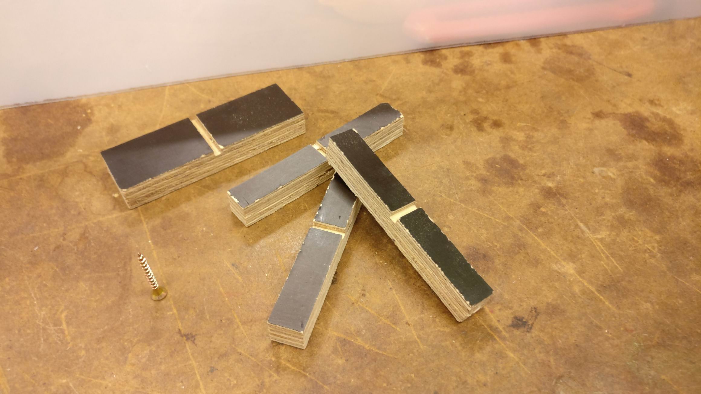
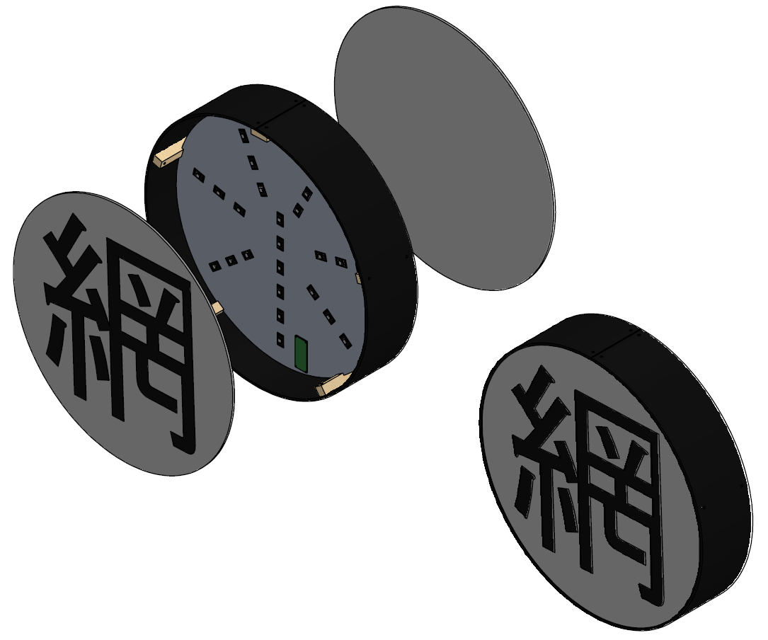
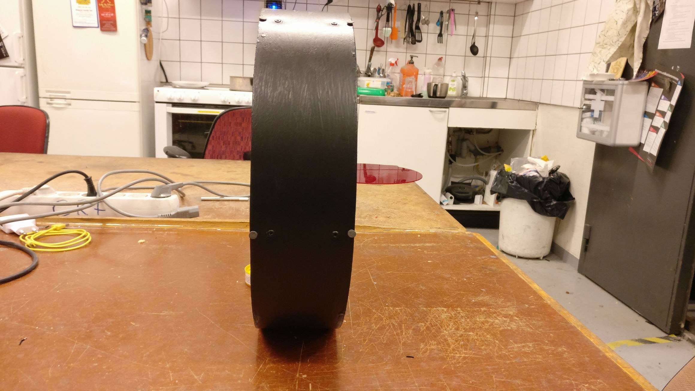
Small wooden block for holding a aluminium plate in a slot.
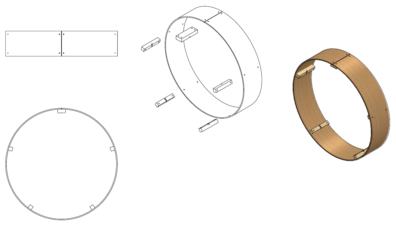
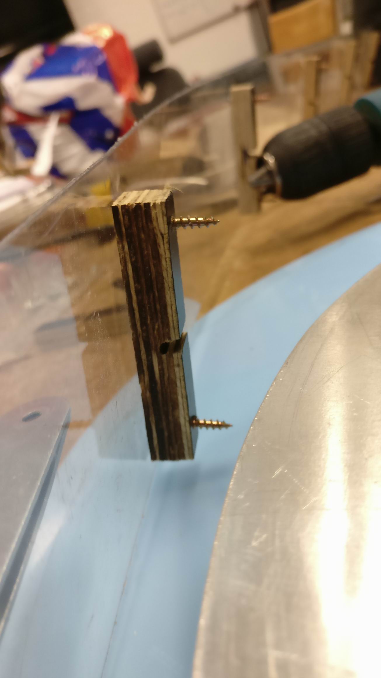
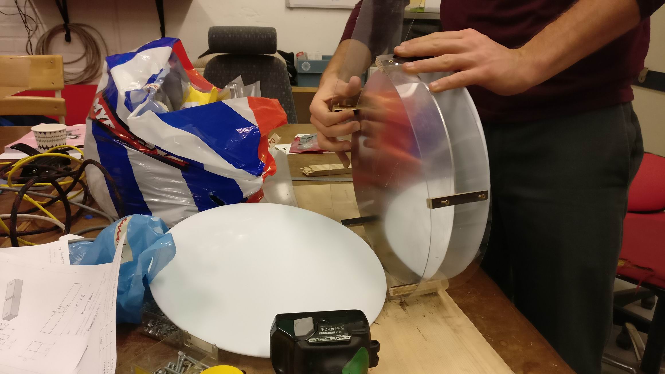
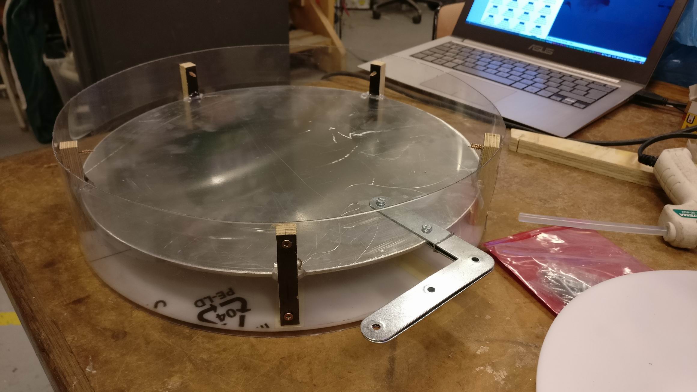
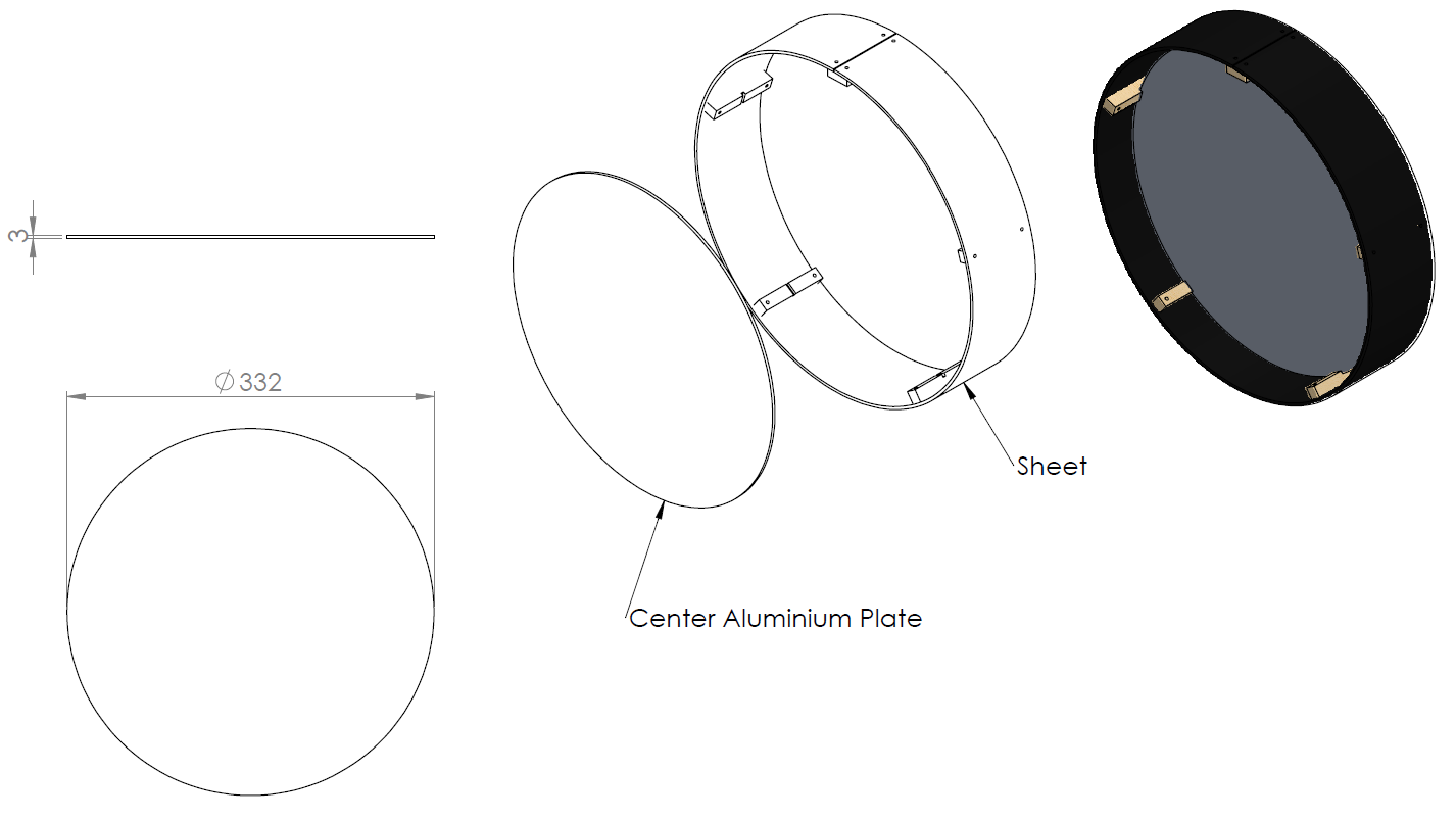
The wooden blocks attached on to a sheet of flexible PET plastic.
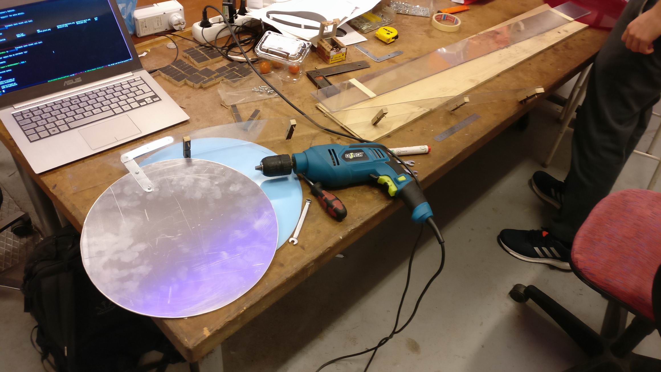
The sheet is bent around the round aluminum plate with the help of the slots.
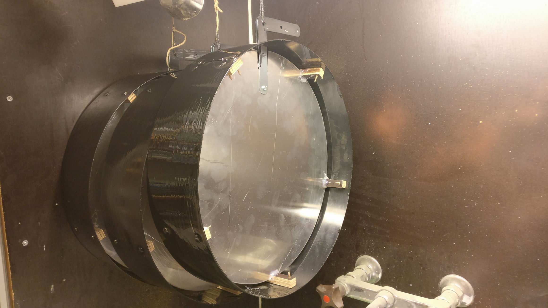
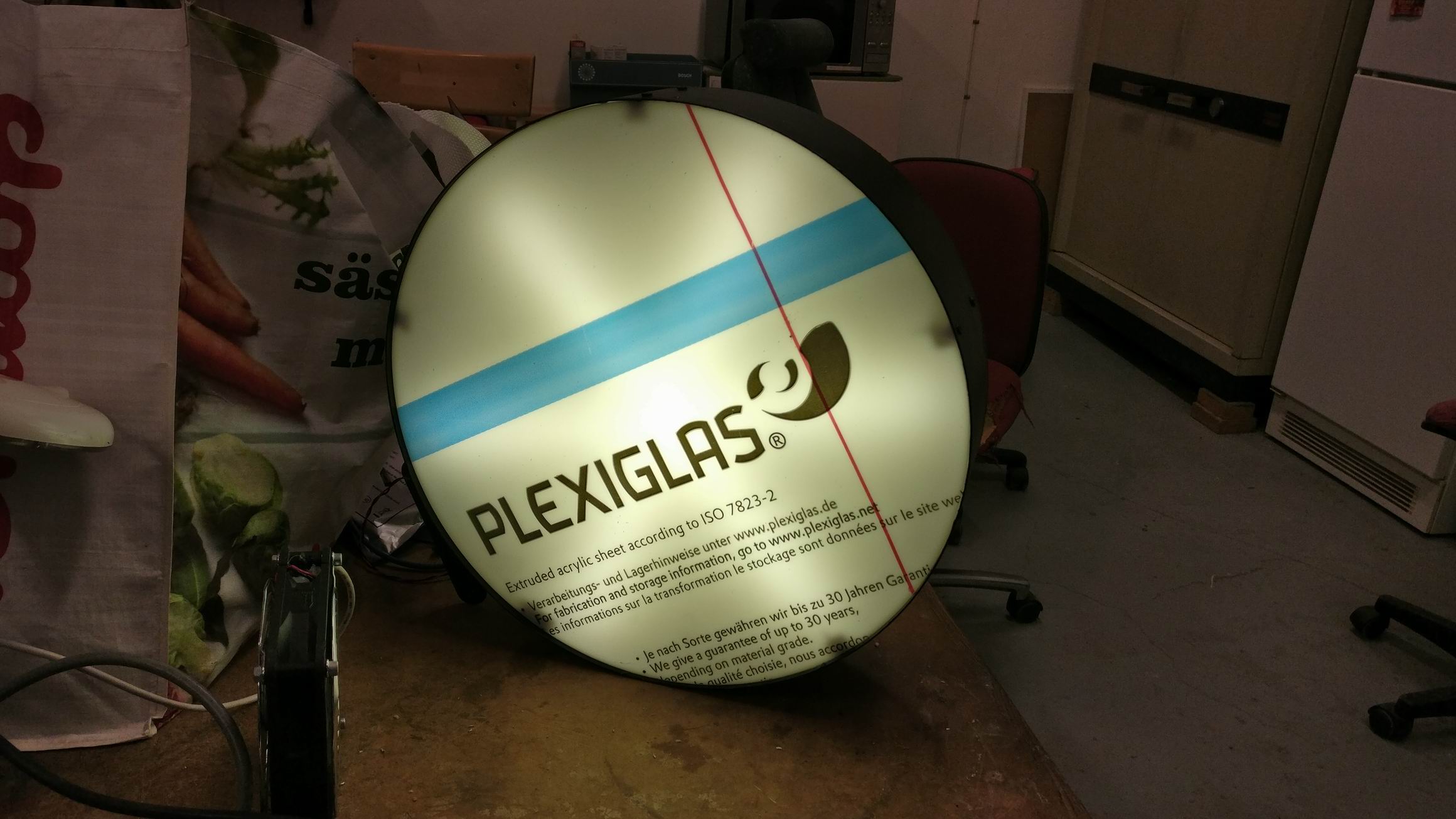
The PET ring is transparent with a blue tint which would not be fitting in a light fixture. So we painted the PET ring in black to make it opaque.
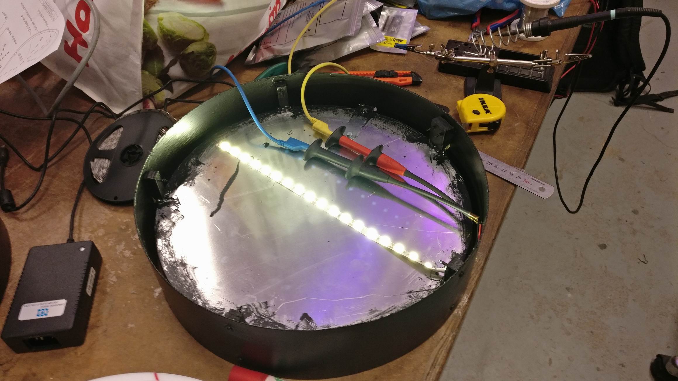
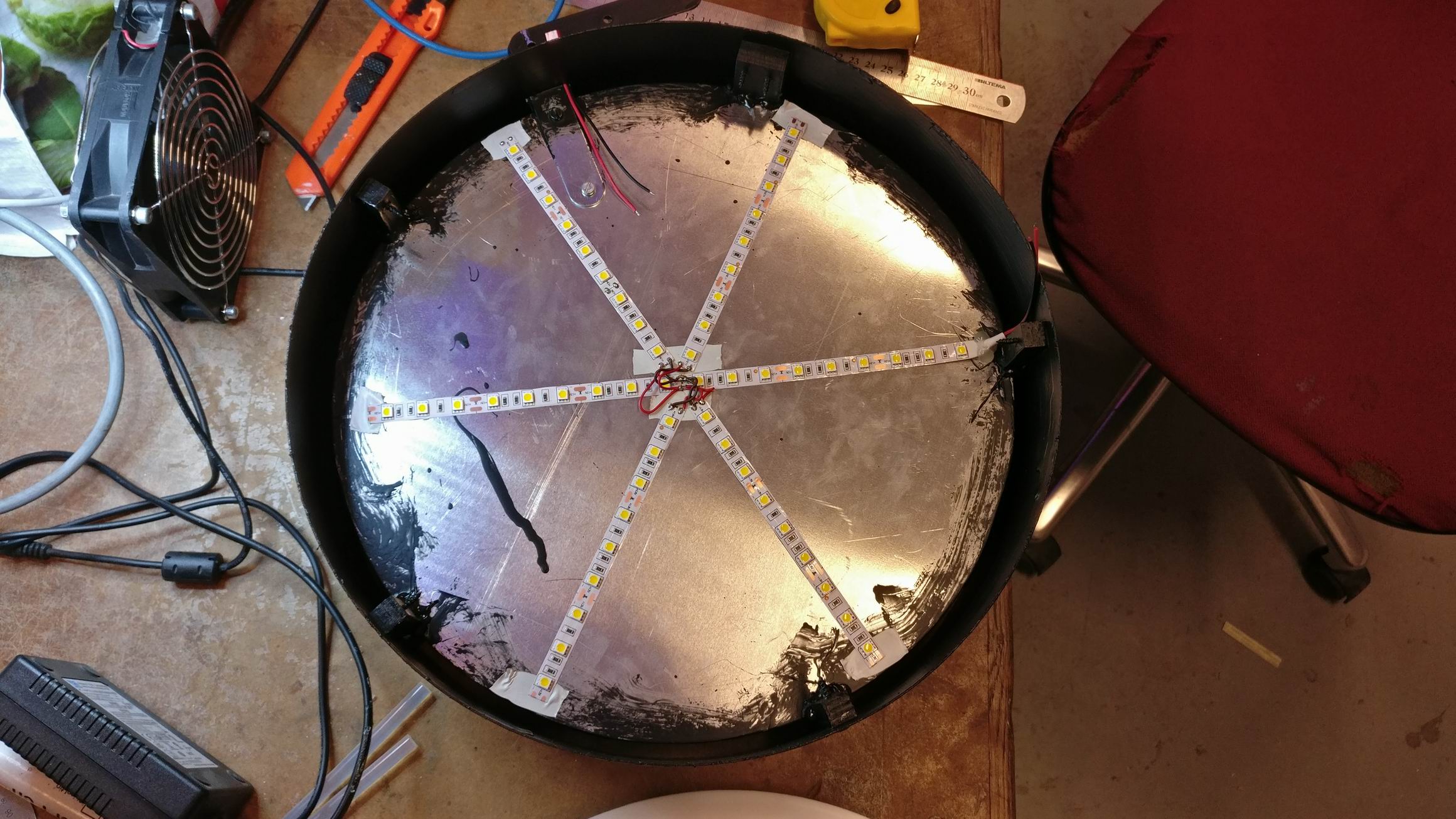
Warm white 5050 LED strip was glued on to the aluminium plate.
9×6 strips with 54 LED’s on each side makes 108 LED’s in total
108 * 20mA = 2.16A
2.16A * 12V = 26W
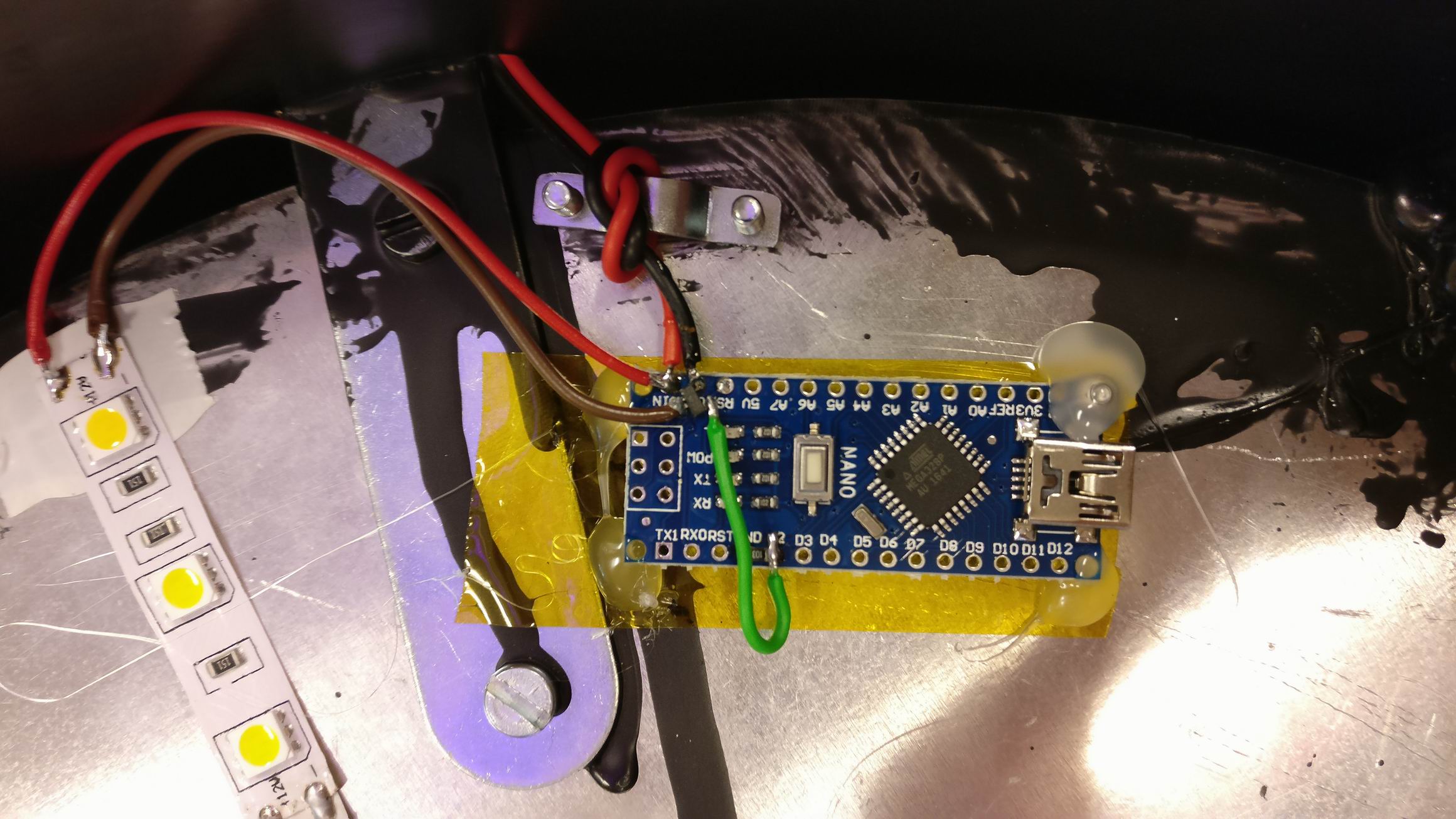
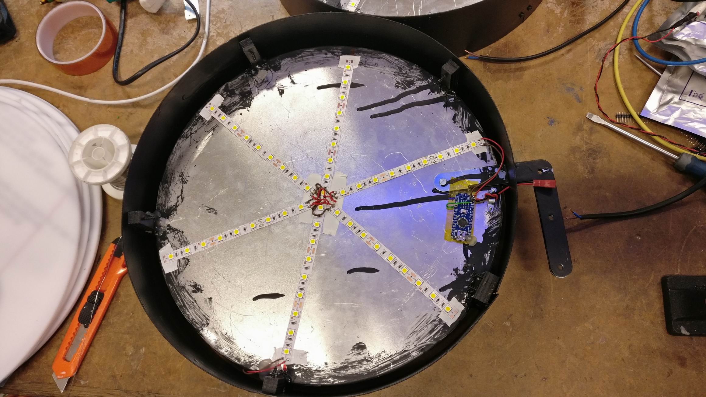
The LED strips is driven by 12V that comes in from JST-connector.
But the sign is supposed to look like an old florescent light, so to give that look the light should look like it flicker occasionally.
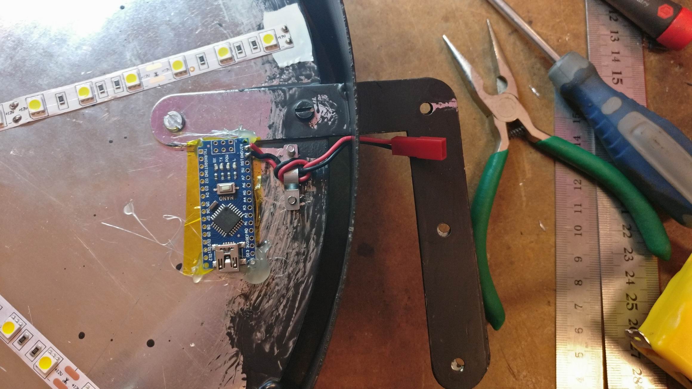
I hooked up an N-channel MOSFET IRLML6344 and connected it to a Arduino Nano for timing the random flickering.
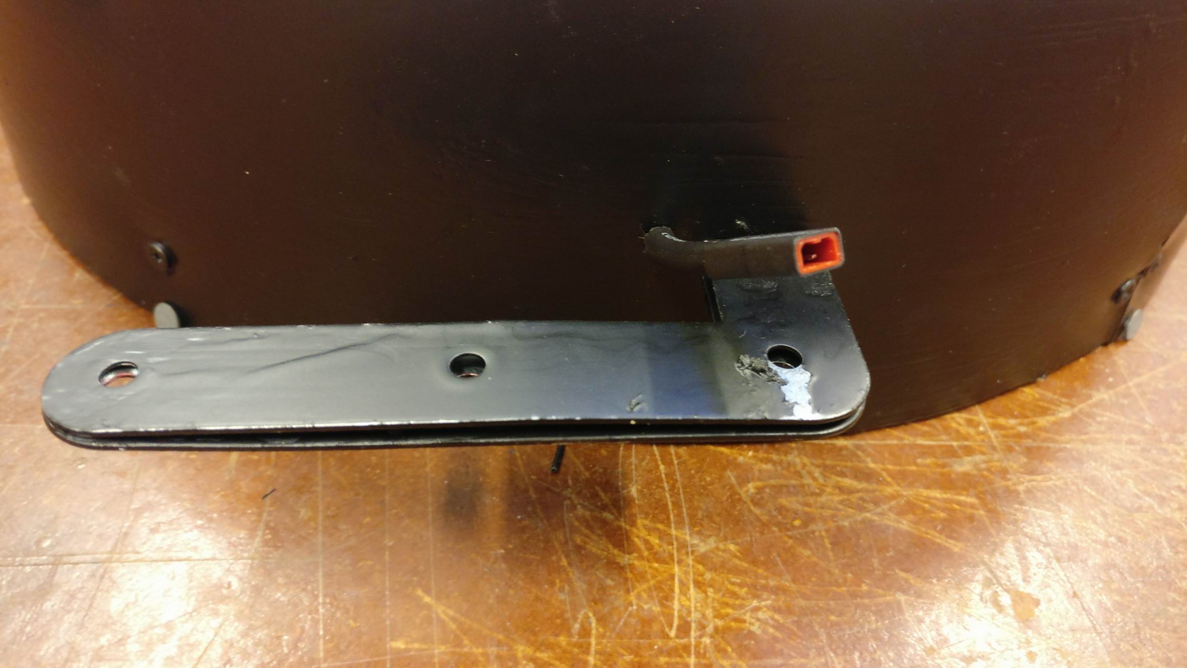
A big steel angle attached to the heavy aluminium plate of the sign, this is used for screwing the signs to a wall. Also the JST power connector, hidden in black heat shrink tubing.
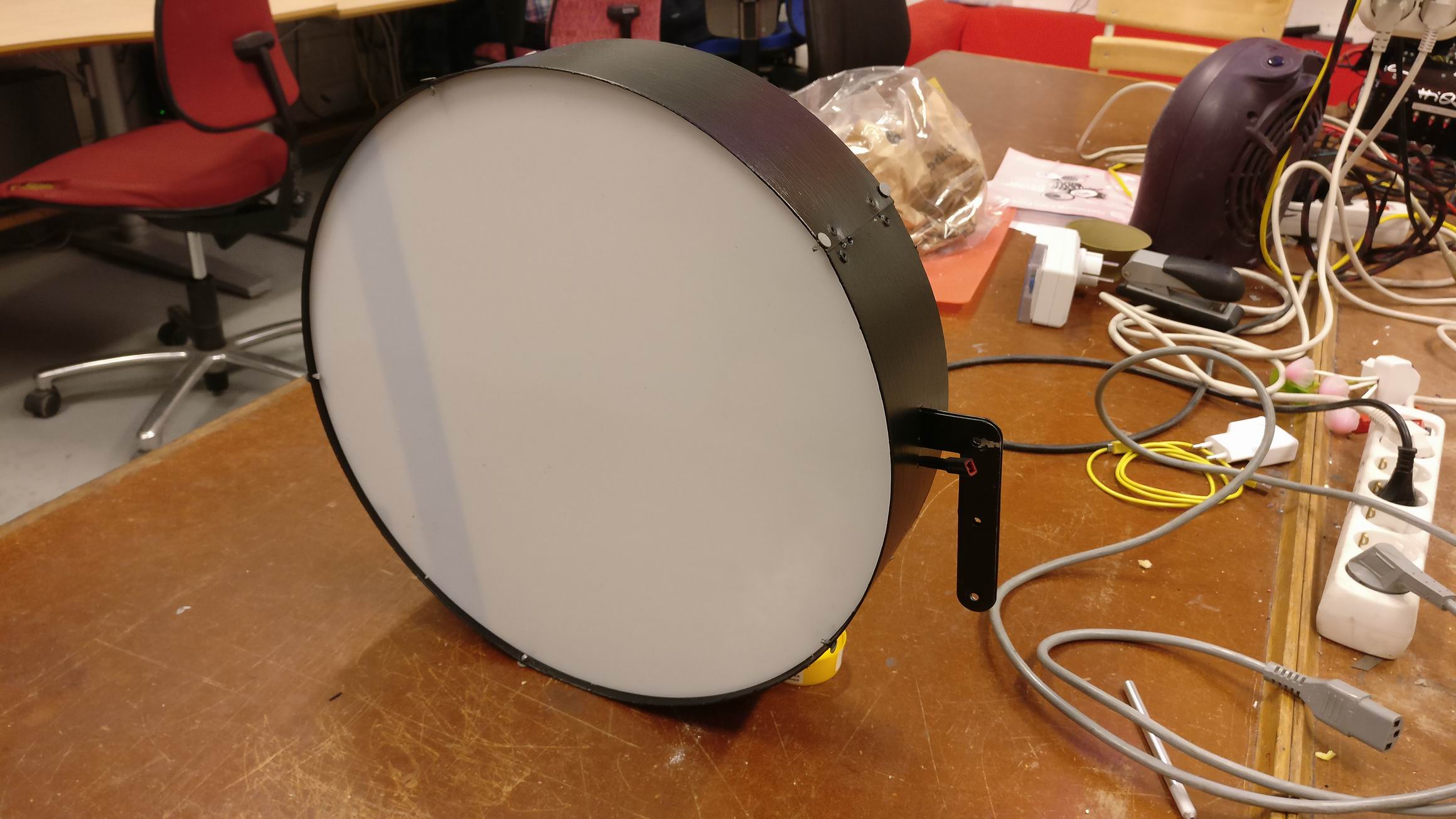
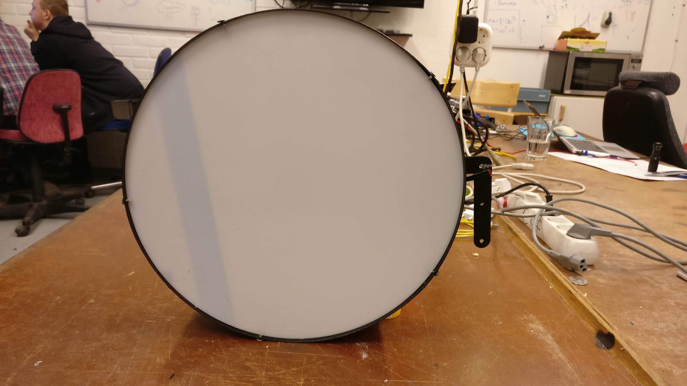
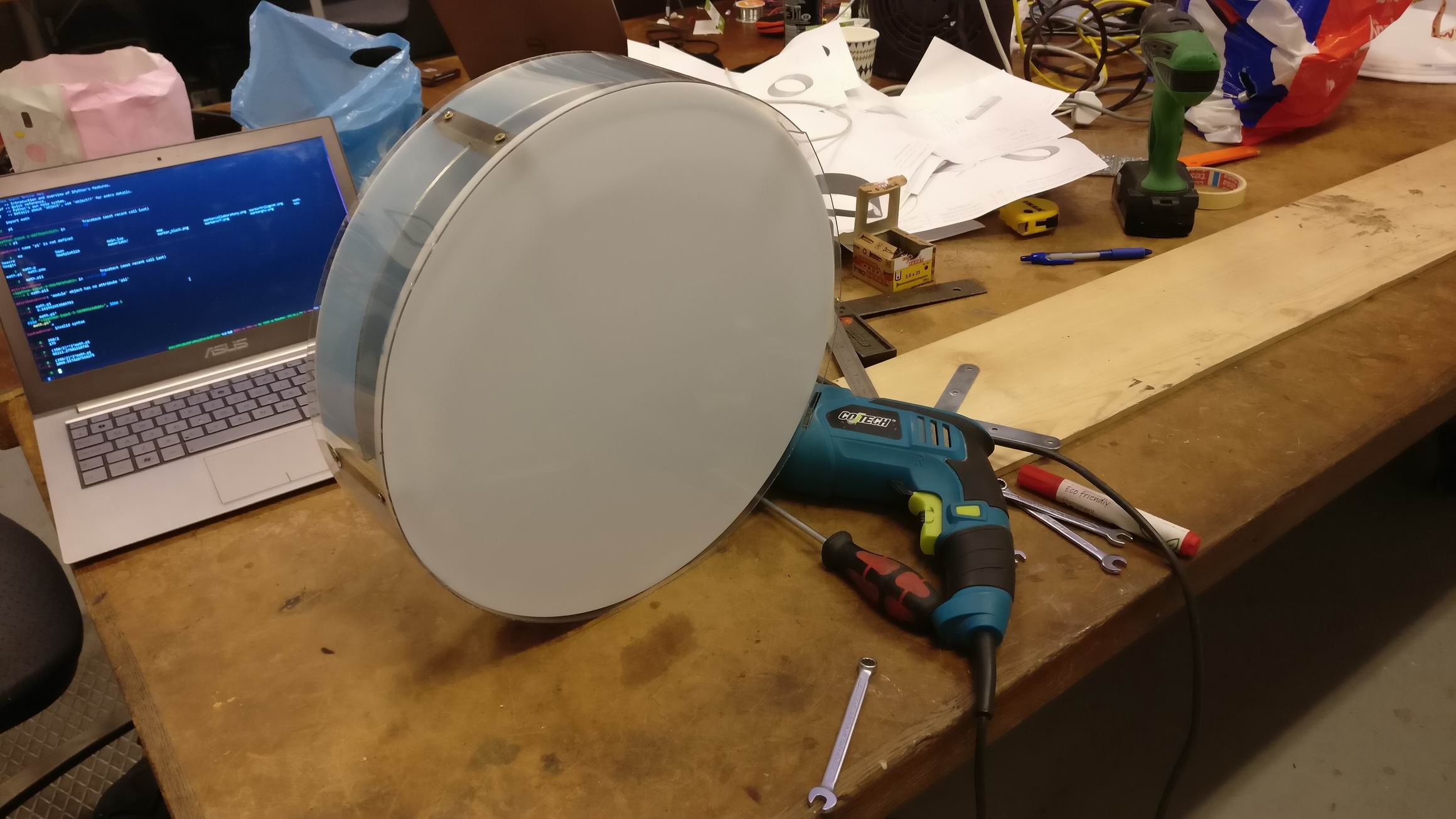
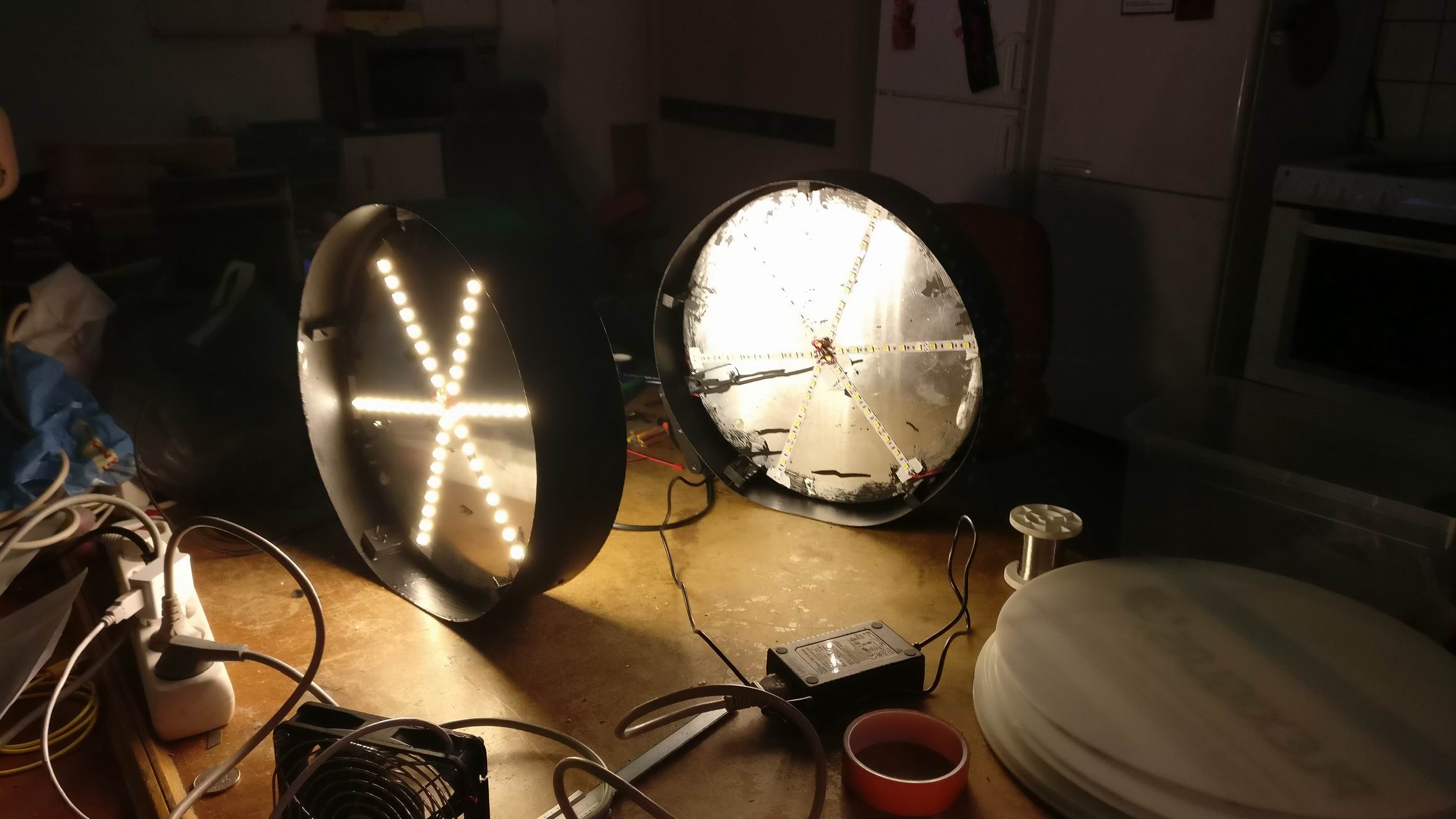
In the outer sides of the sign round white acrylic plates will be inserted. They will rest against the wooden blocks and hold back by small sprints.
Each side of the sign is mirrored, so one sign have two faces.
The light is powerful enough to project through the white acrylic plastic. And with opaque paint on top will make a huge contrast perfect for a sign.

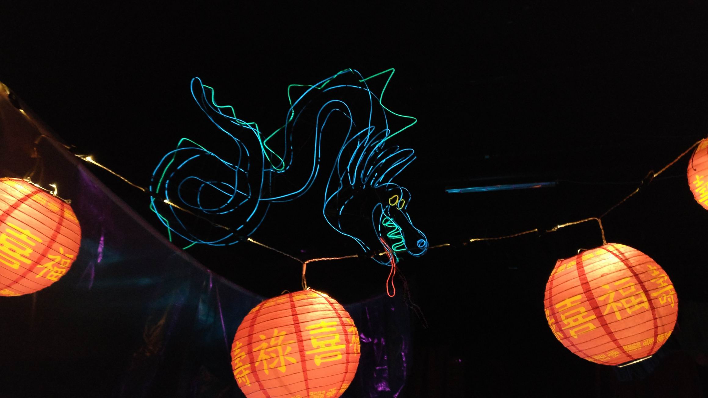
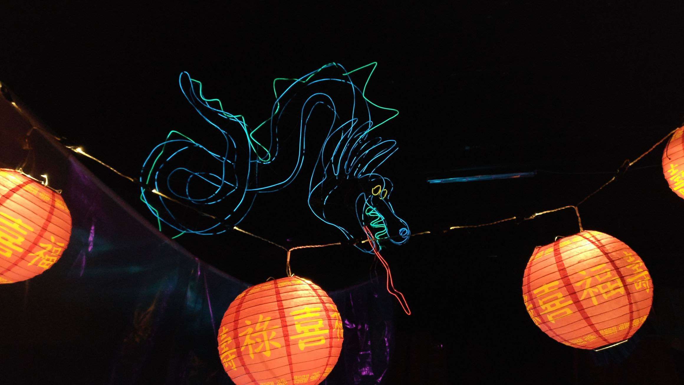
For the larp Do Androids Dream we needed a lot of small props to give a Blade Runner feeling of the scene.
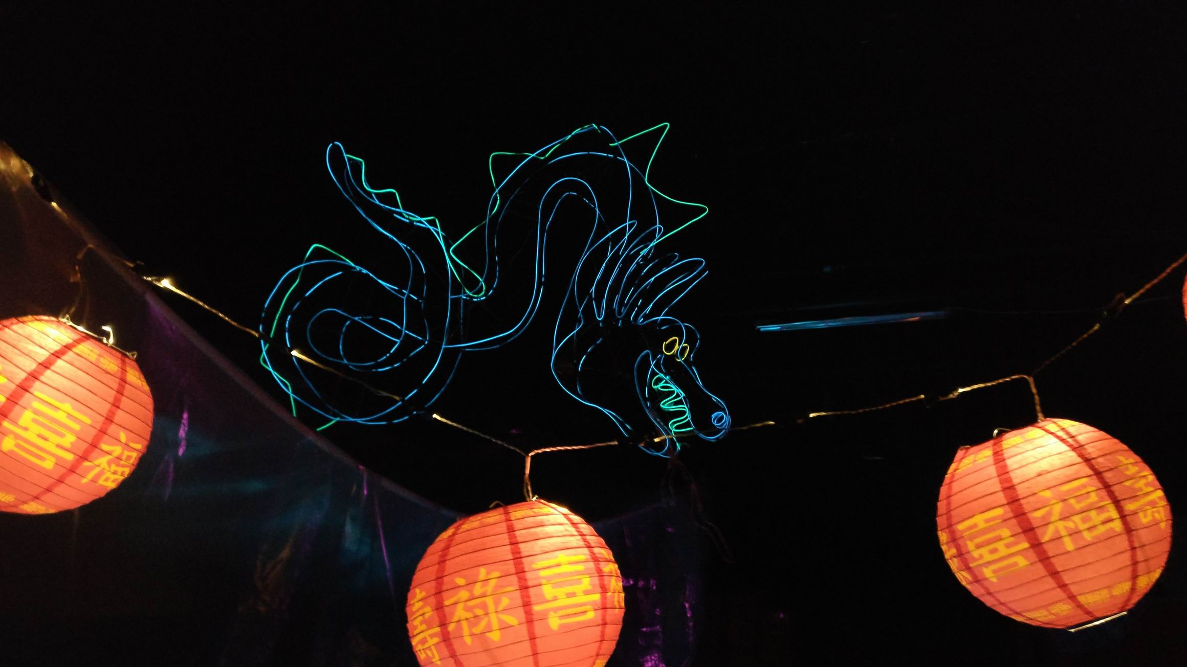
An iconic part of the movie is the dragon sign above the Noodle Bar. I thought i could be made out of el wire and it could, it even looked like neon. The light emitting from the el wire was really low doh, I would prefer to have stronger light.
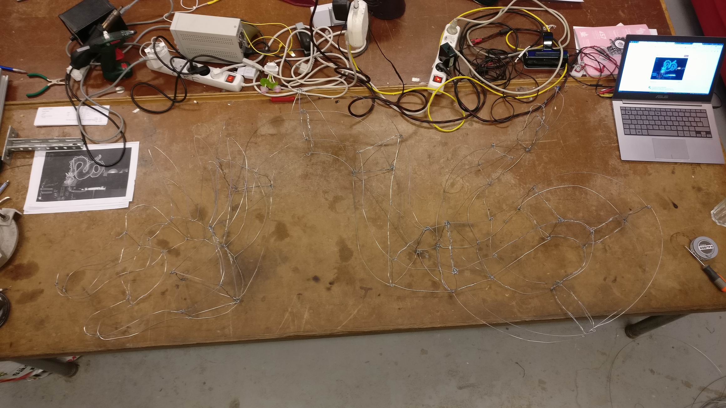
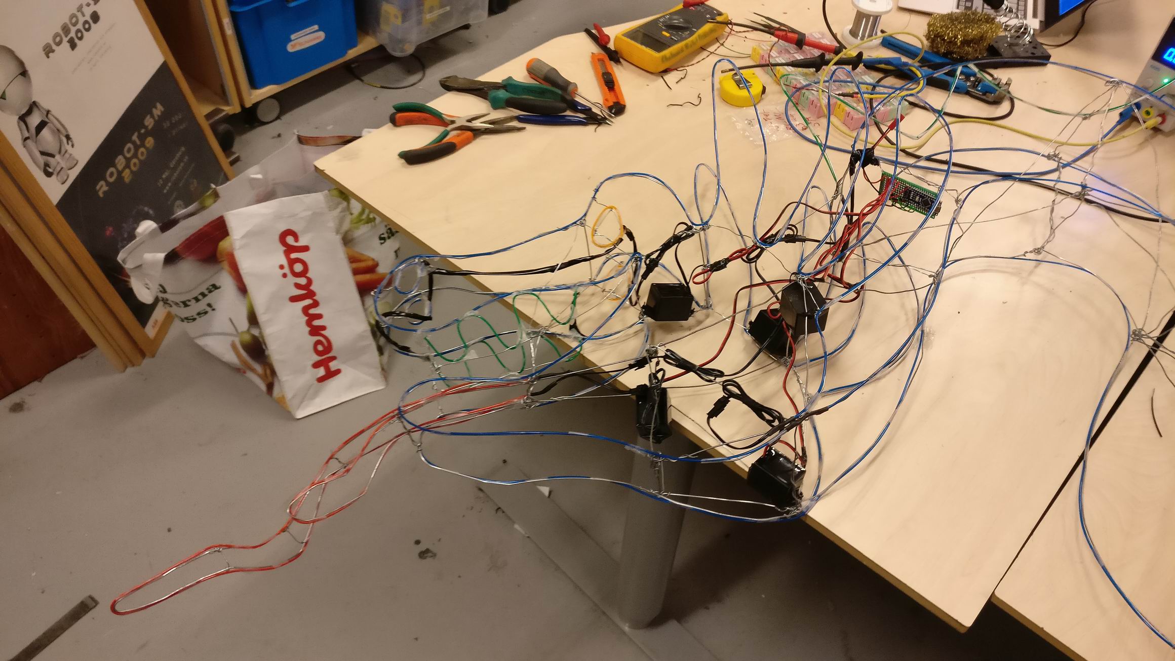
I started out by placing steel wire in the dragons shape by hand.
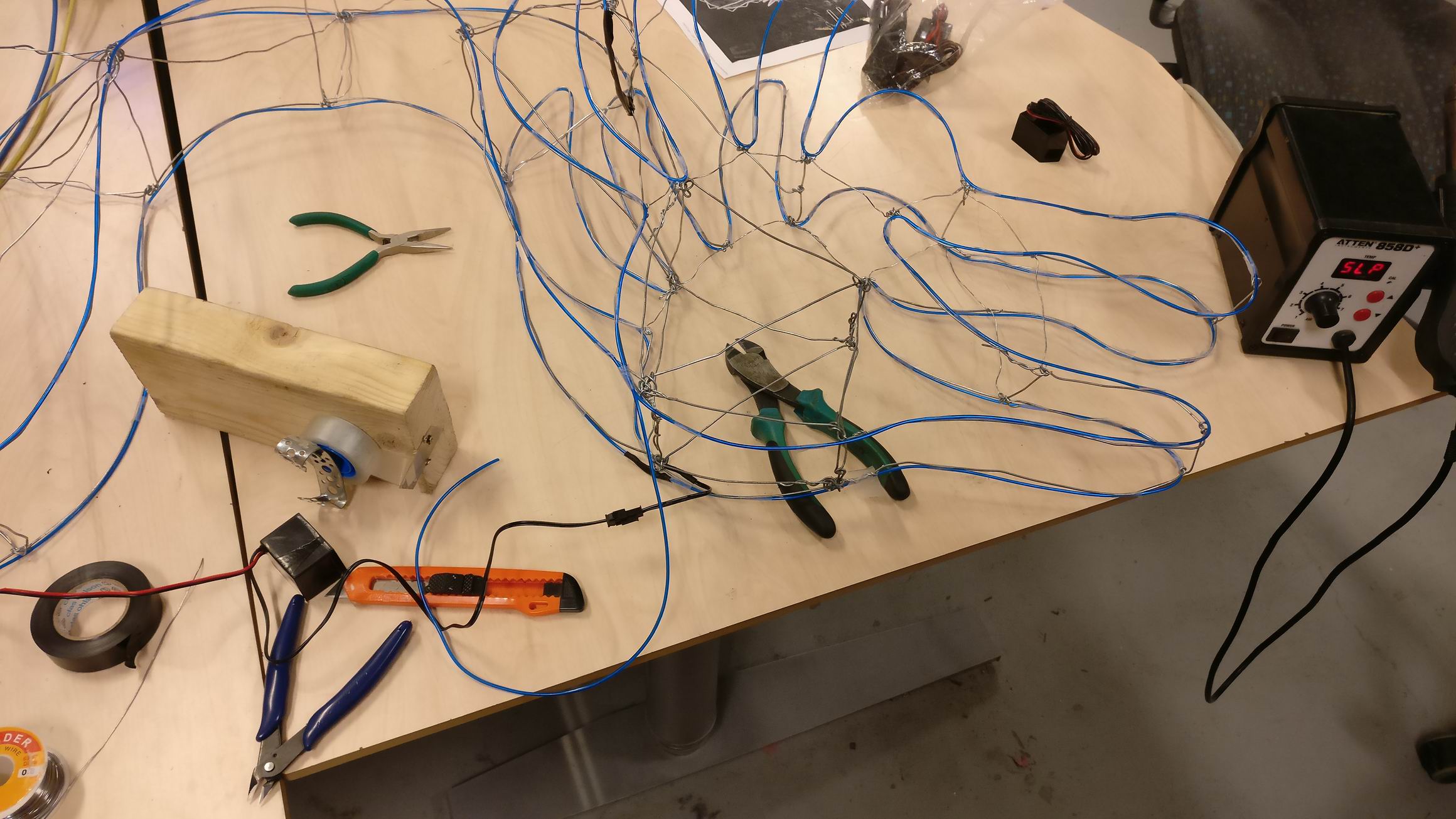
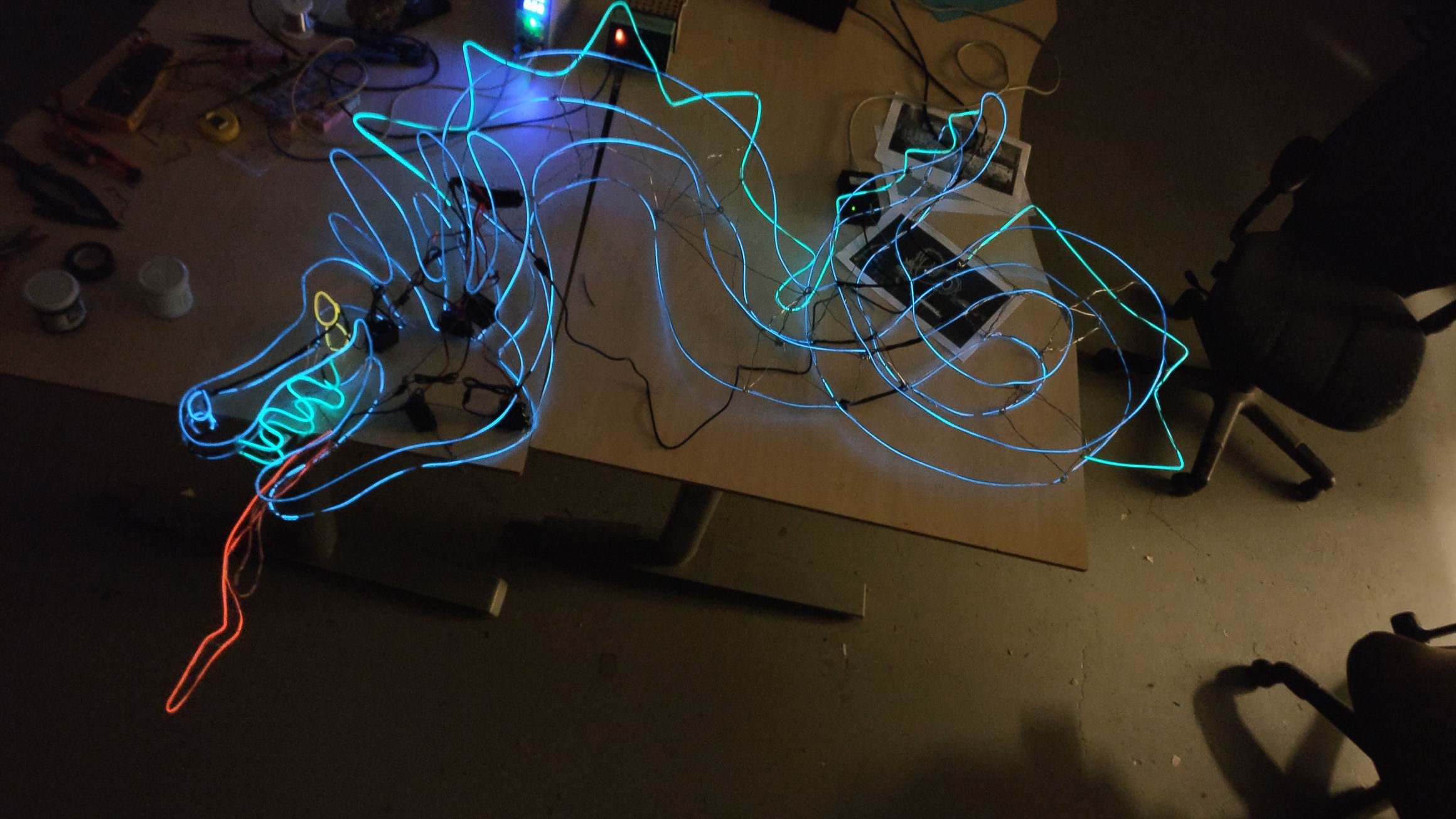
Attaching el wire around the steel wire frame was quite easy, just a matter of placing some transparent tape around it.
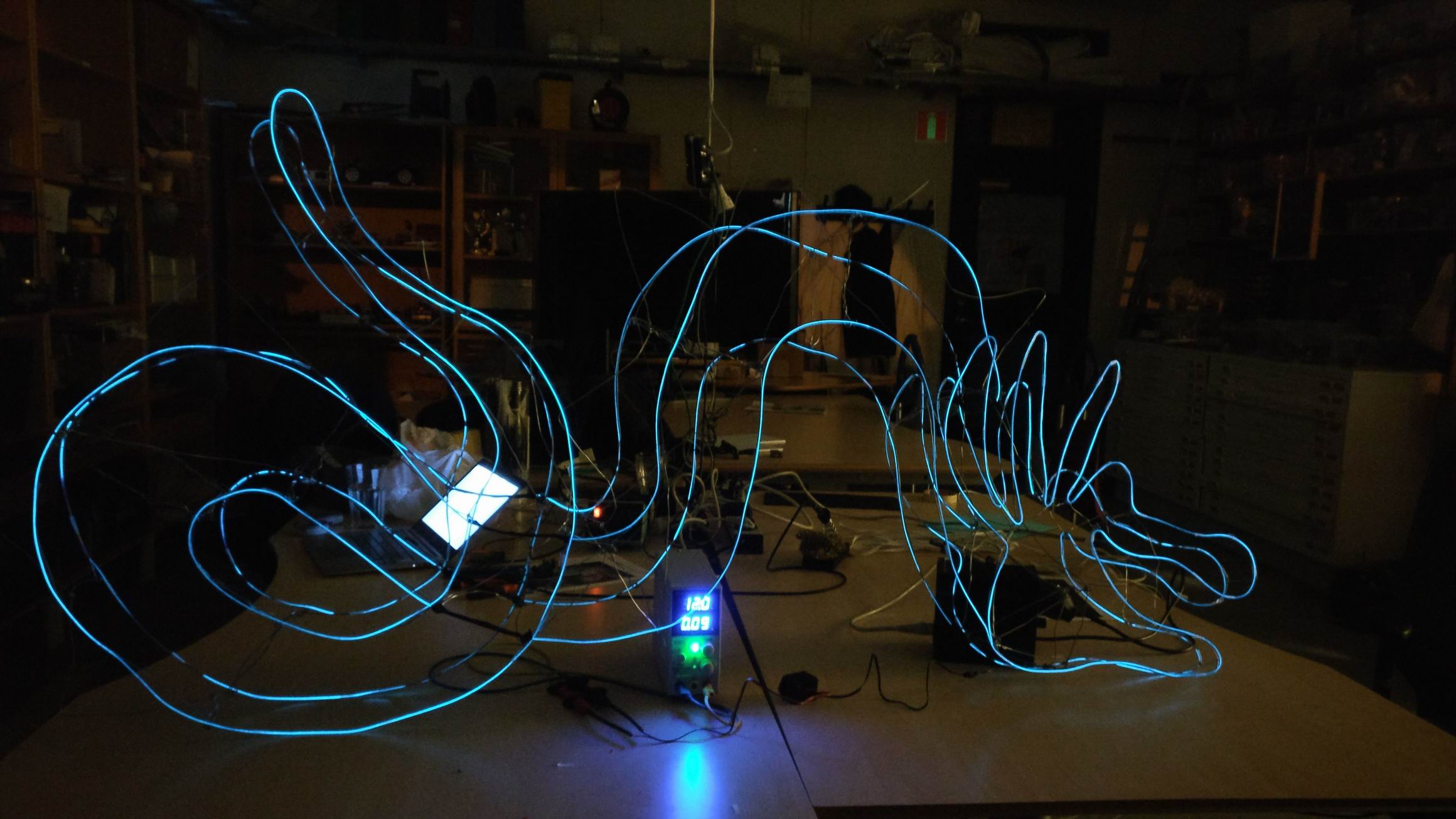
When trying out the outer shape I know I was on the right track, it looked great!
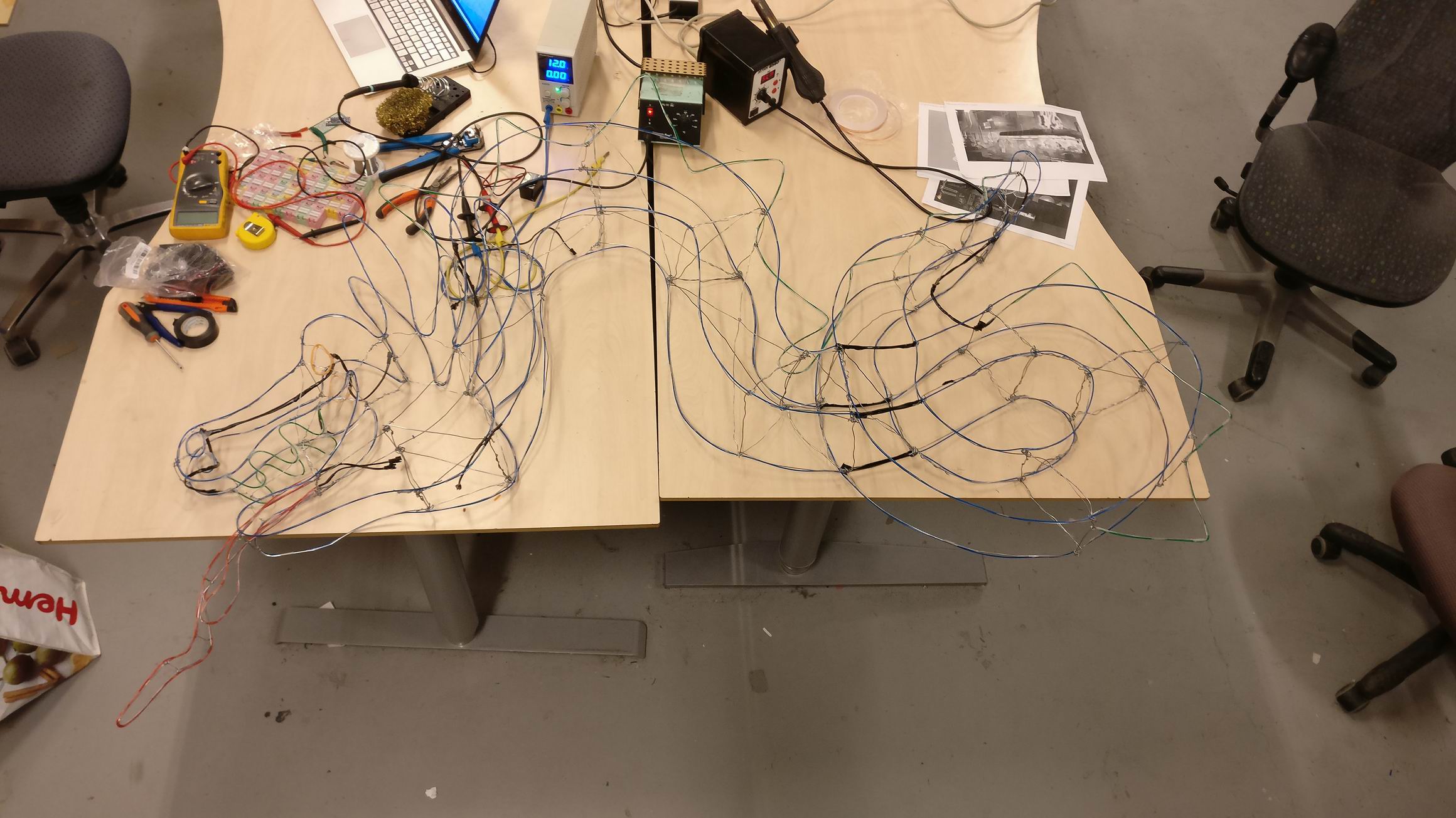
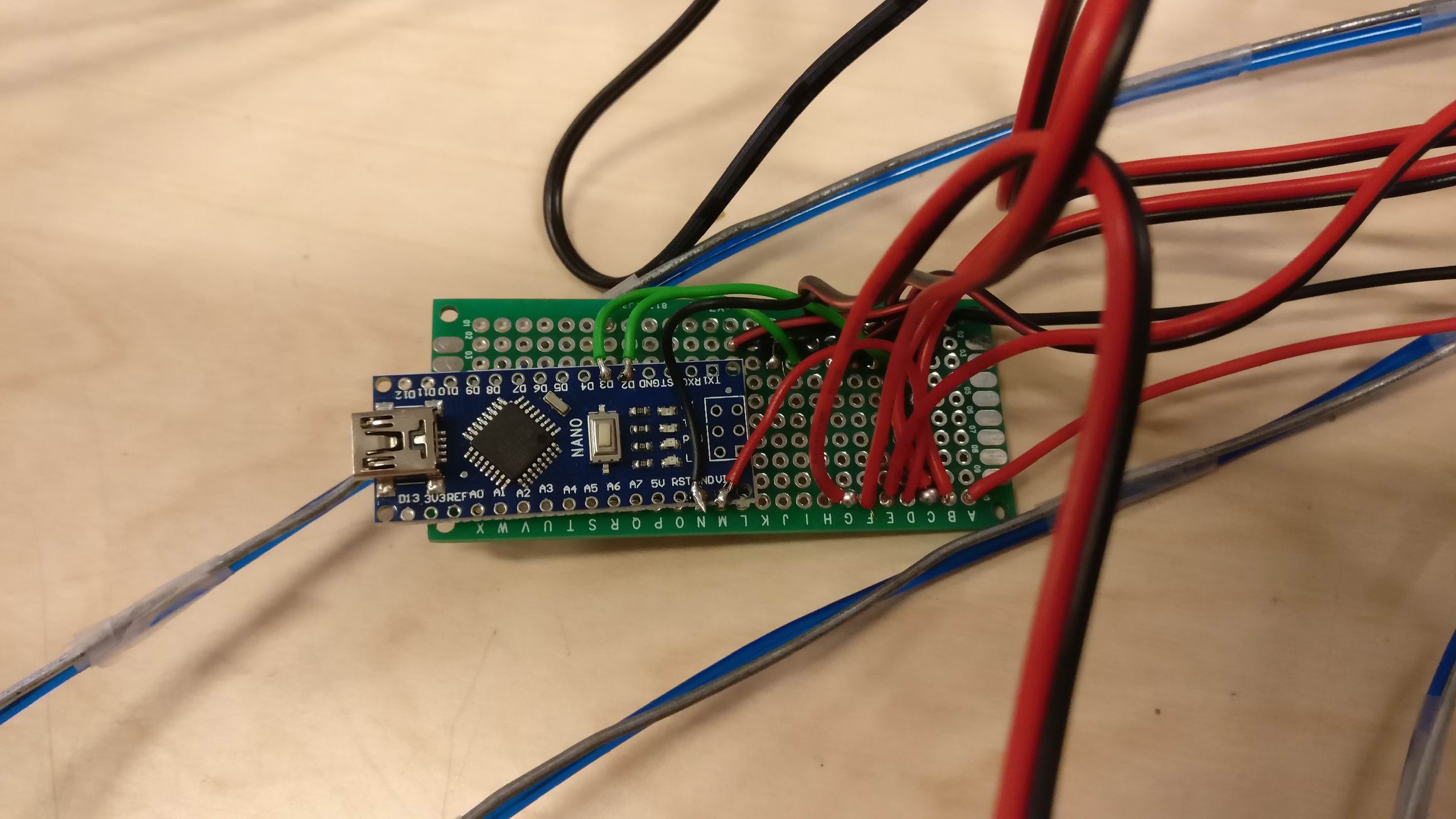
The dragons tongue is animated in the movie, it’s animated in segments. I was after the same look, so I created two segments for the tongue and had the idea the enabling each segment by turning on and off the high voltage el wire transformers.
I connected a couple of N-channel MOSFET IRLML6344 and connected it to a Arduino Nano.
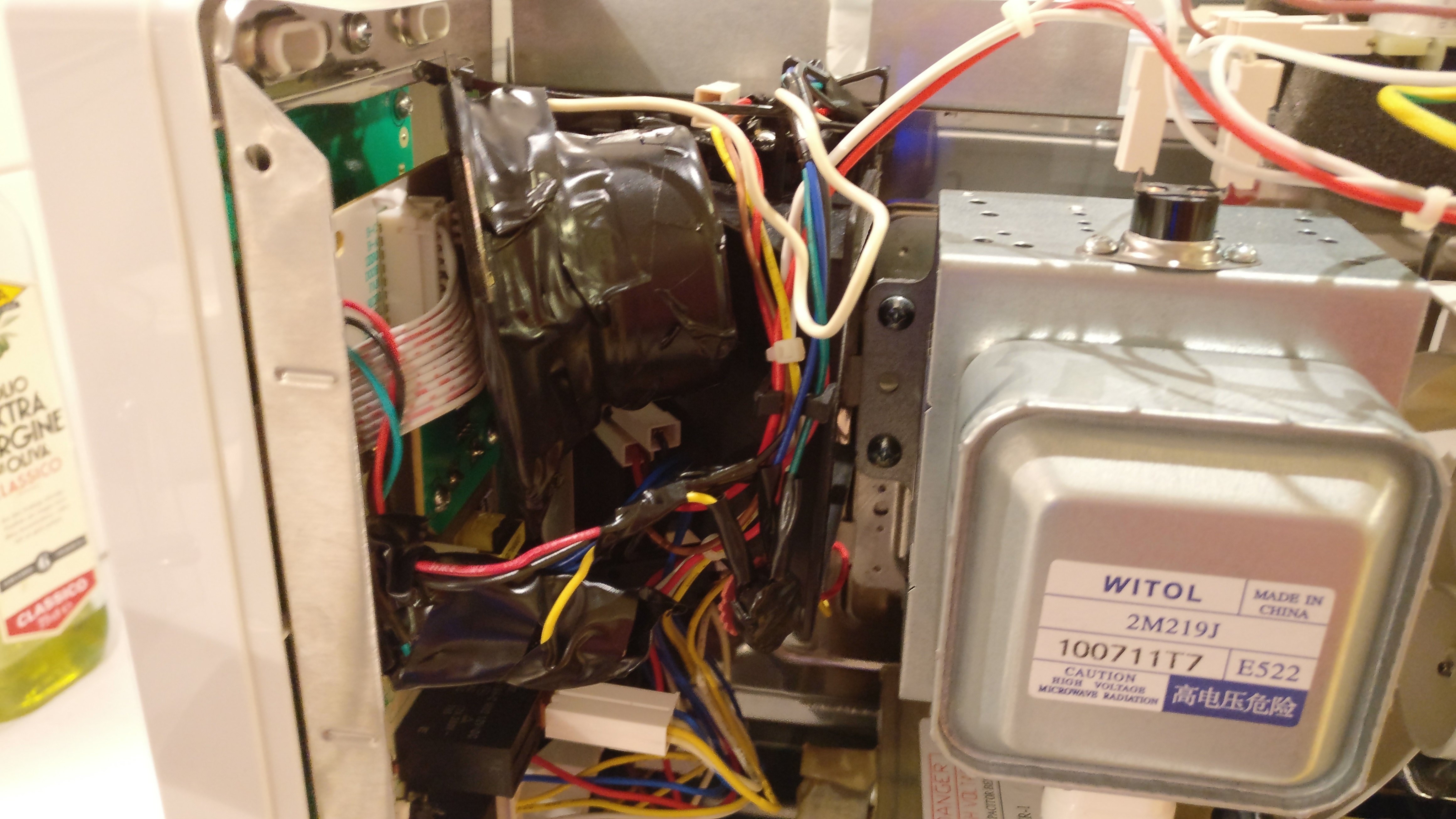
I’m tired of the buzzer in the microwave oven that is beeping constant up to a minute.
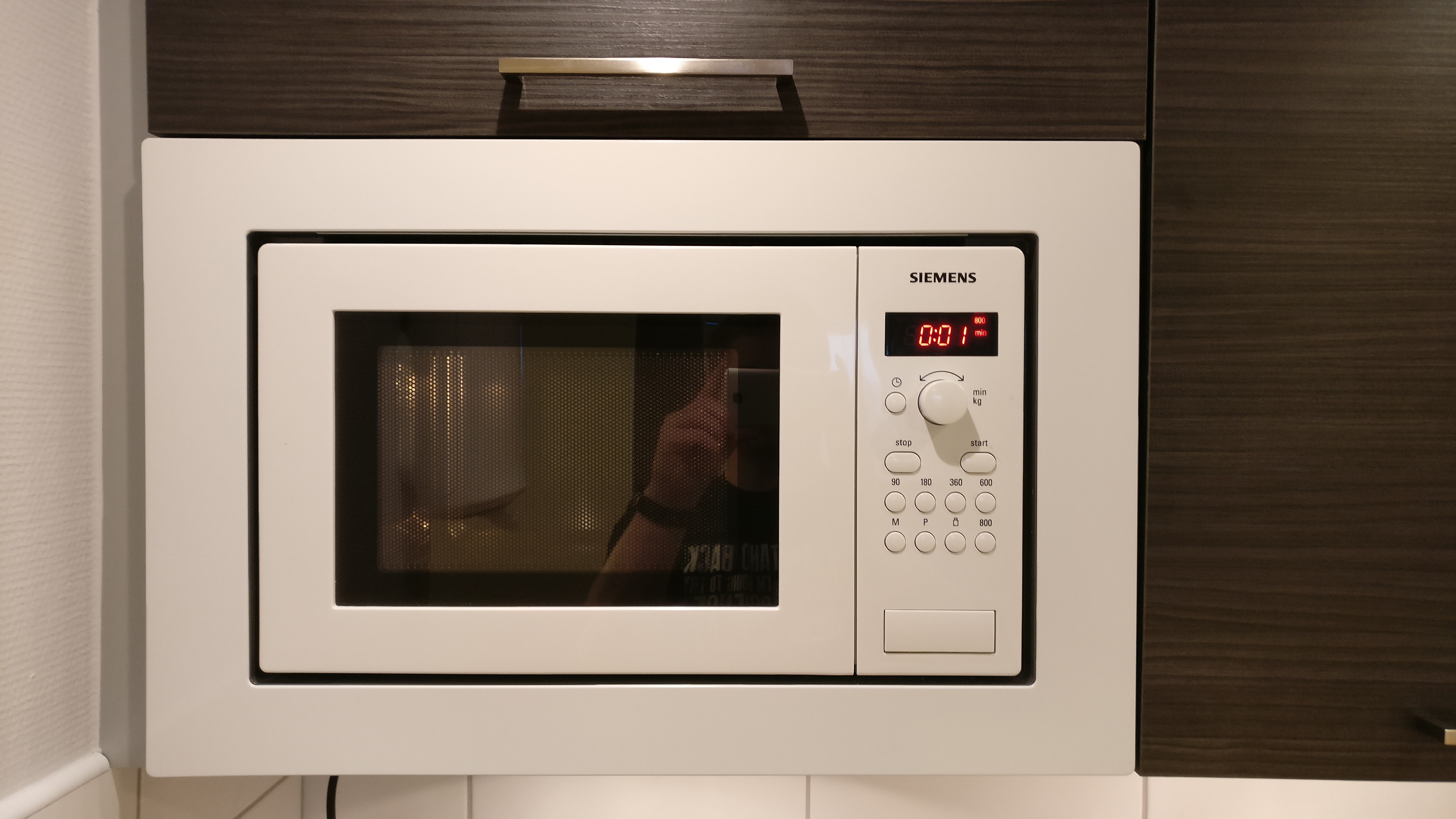
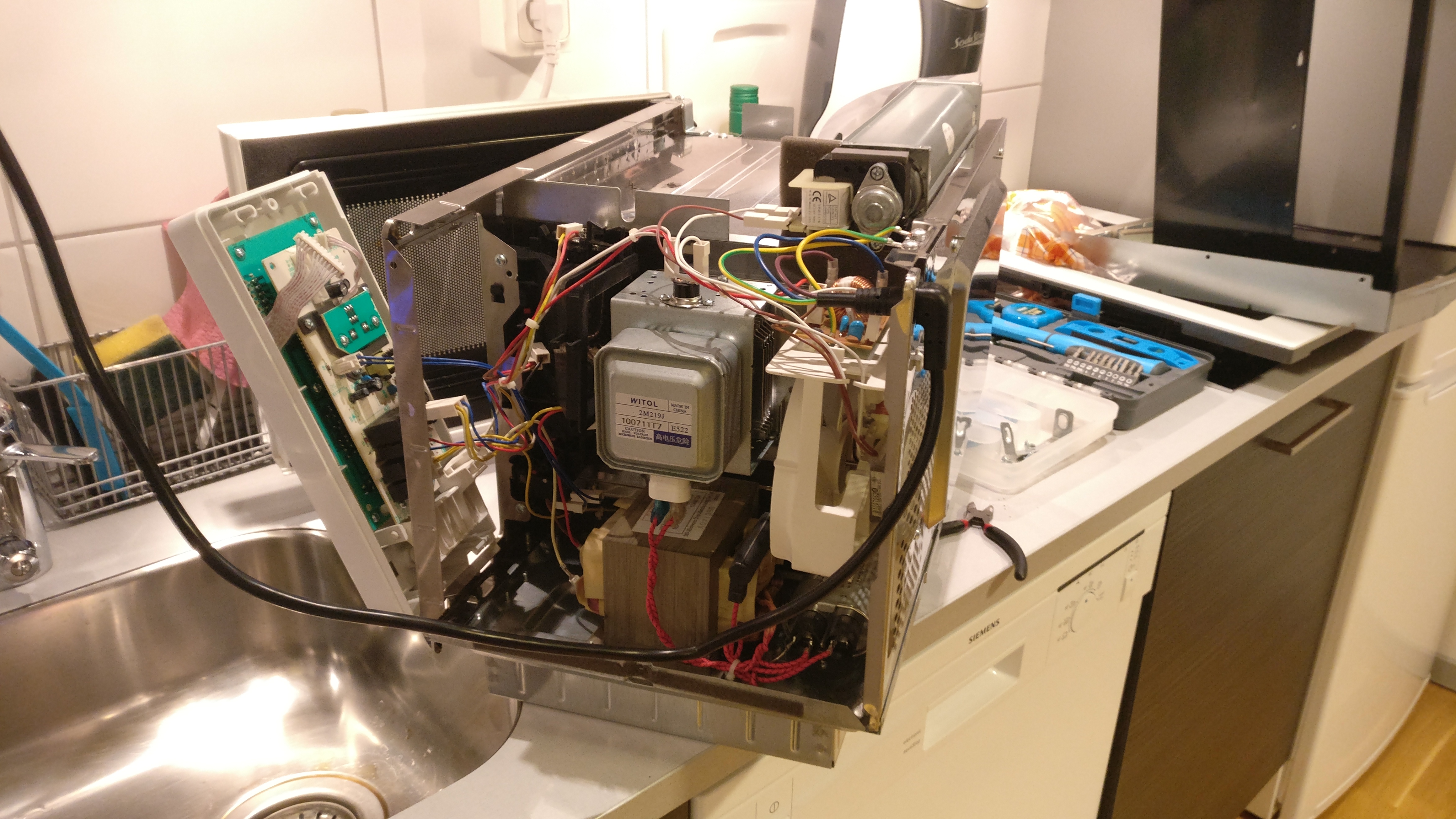
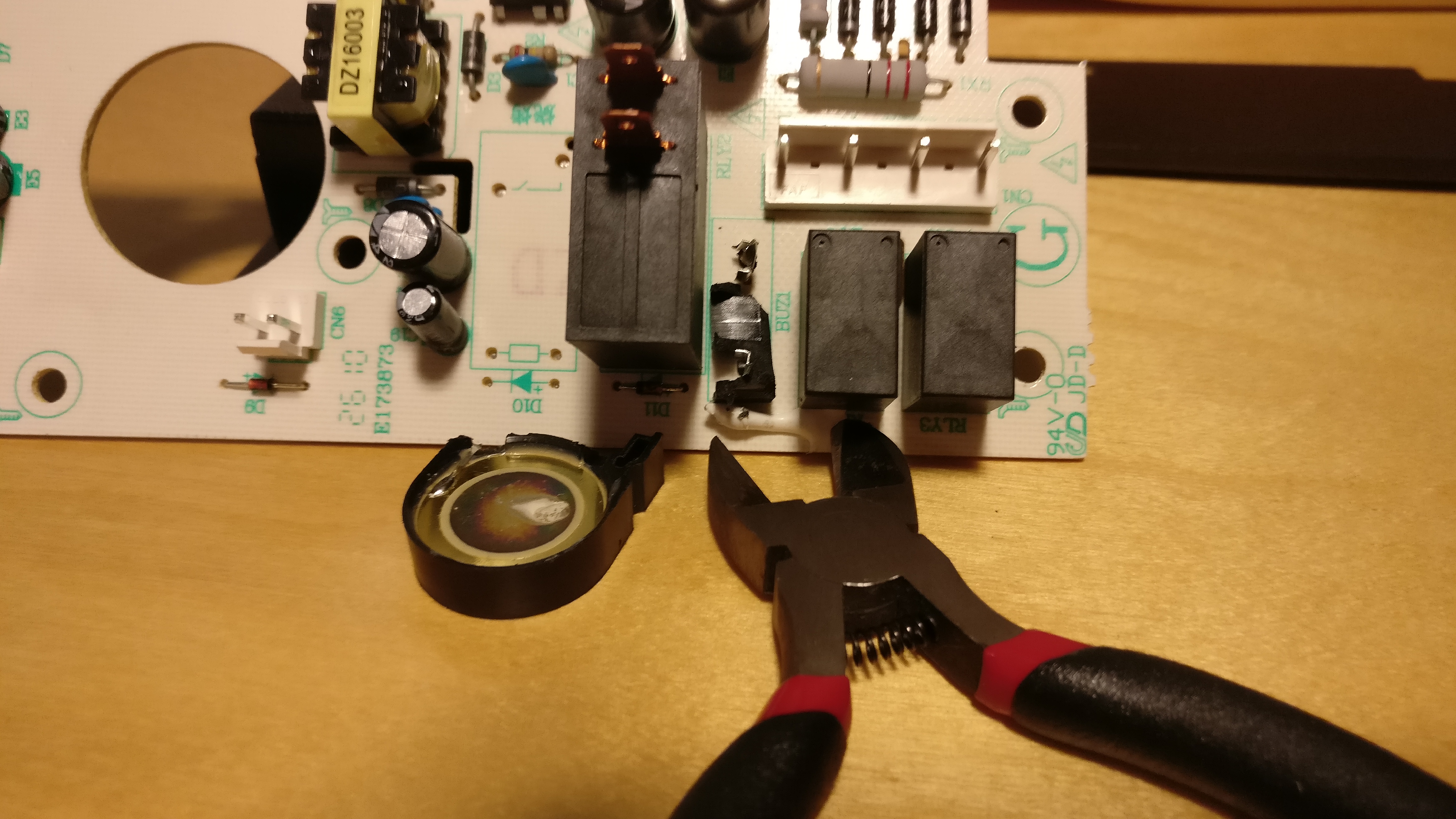
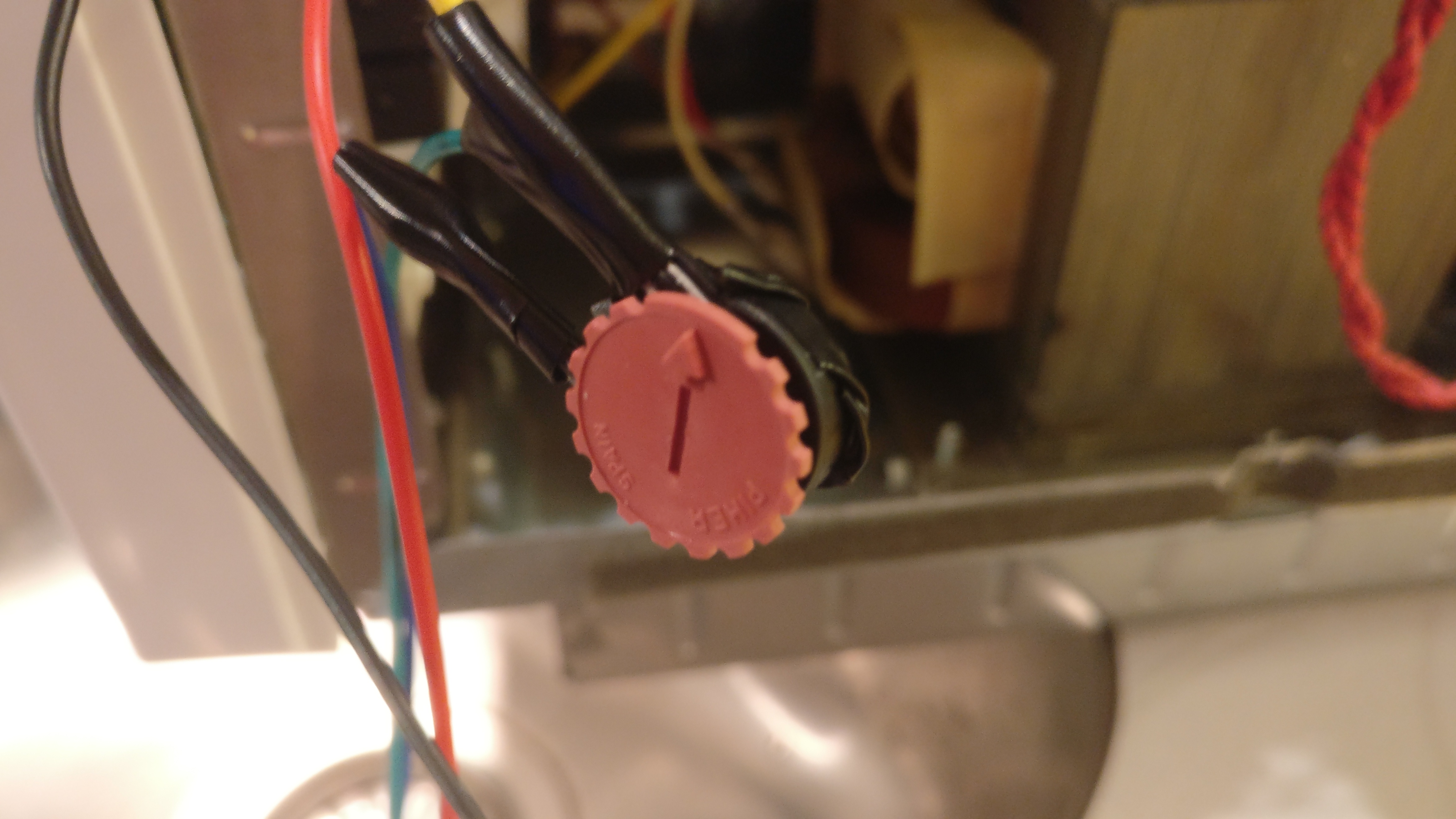
So I opened it up like any normal hacker would, found the buzzer and snapped it off.
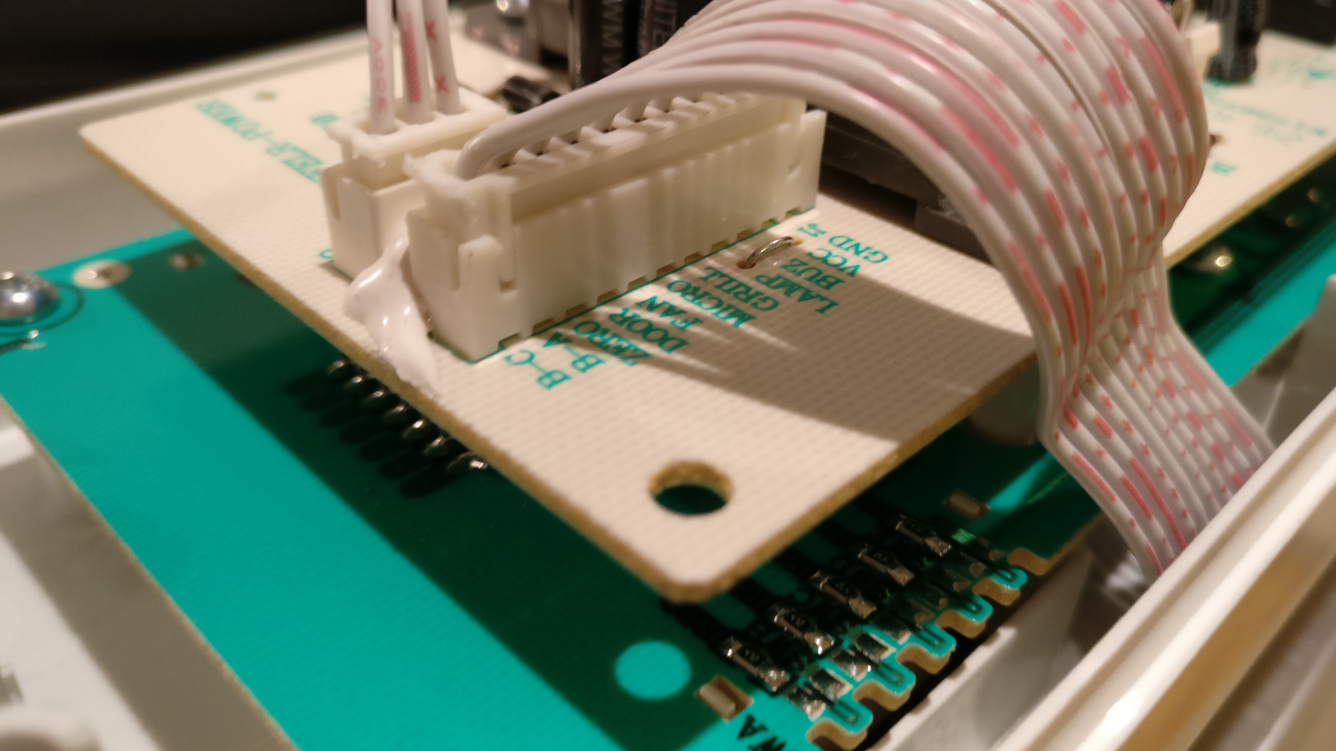
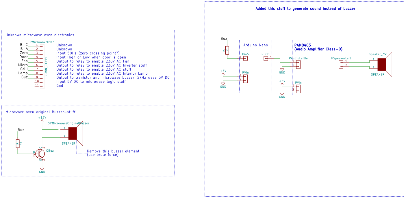
Sure, the buzzer was irritating, but so would be not to hear when my food is cooked. So i quickly had a look at the PCB and find a very interesting pinout.
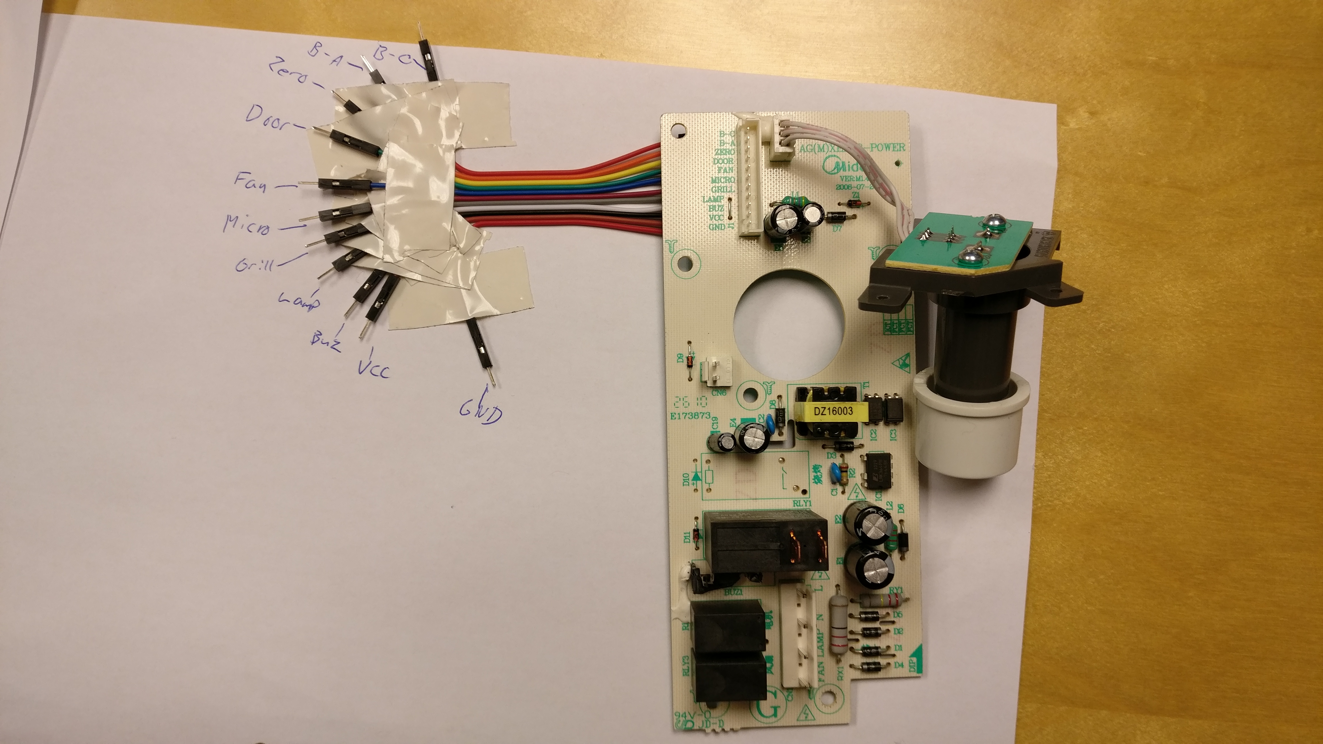
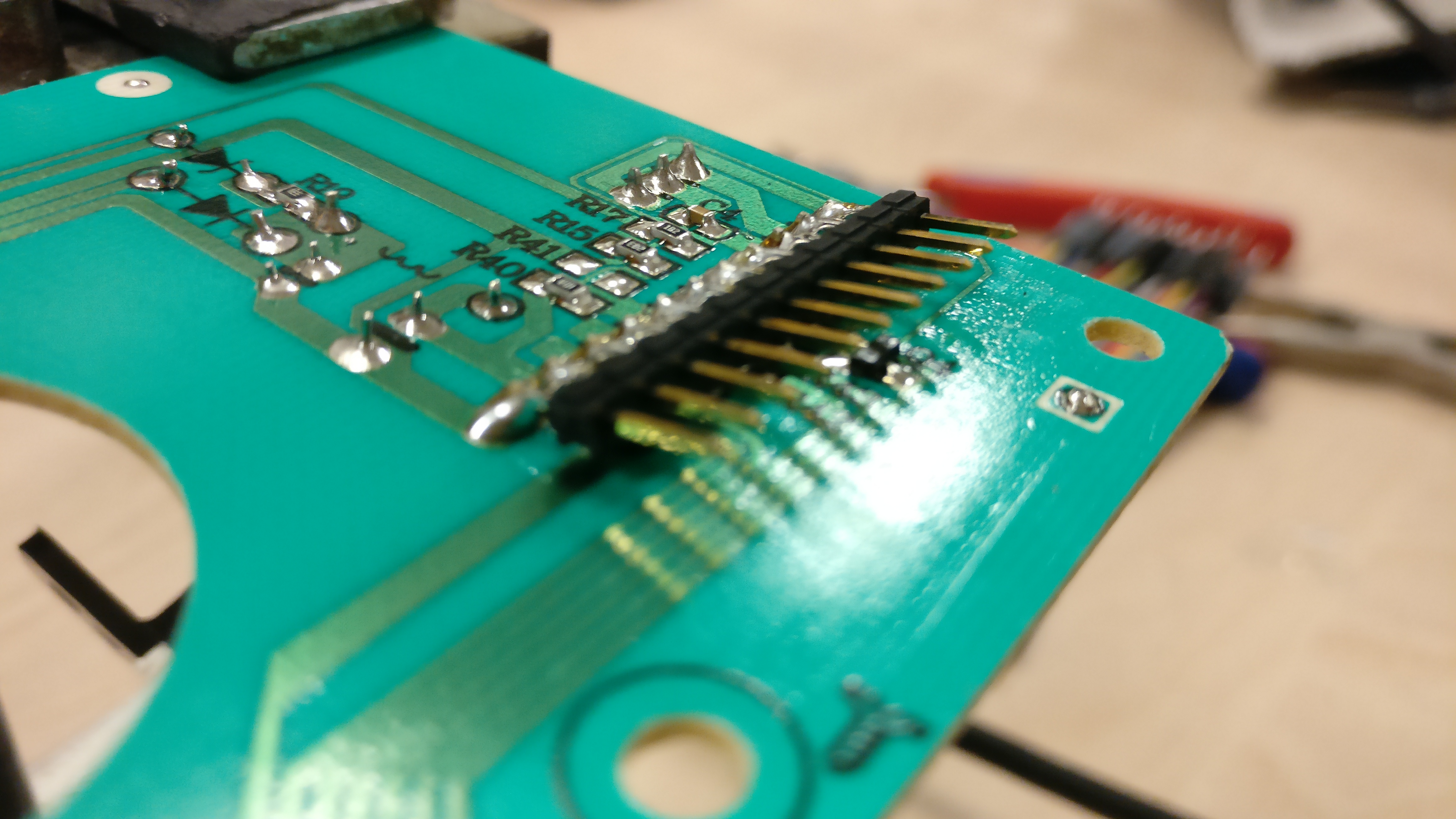
So I soldered on some pins and started to measure the voltage level.
VCC of 5V looked promising for a microcontroller.

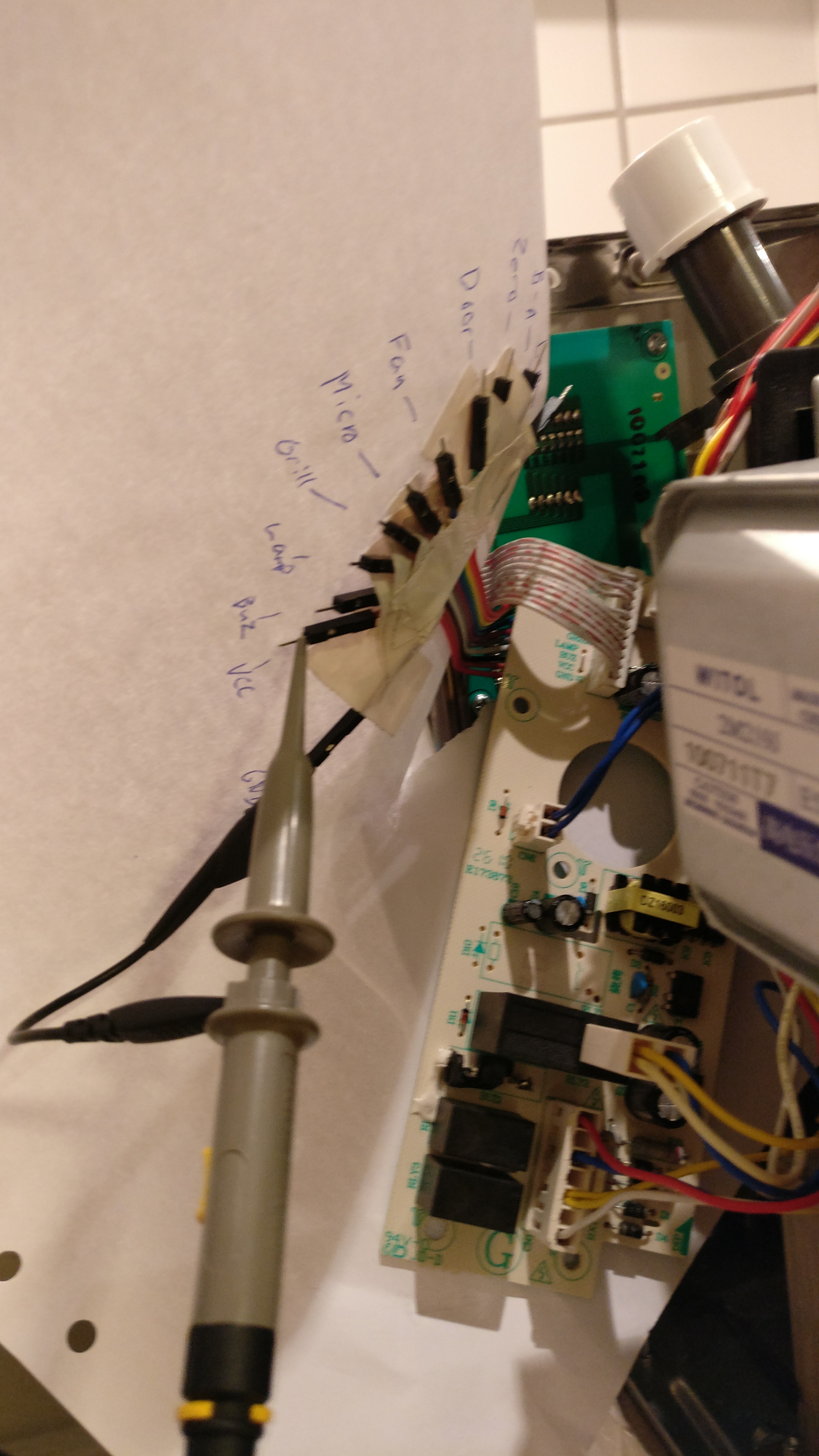
I had a look at the buzzer signal, it was a 2kHz signal with an amplitude of 5VDC.
I had a rough idea in mind about having a small tune play instead of the 2kHz tone, and it should only play once.
So I shuffled some code together to code to play a small tune from the flash of an Arduino Nano. The flash could only hold about 18k of samples and was played at 8kHz.
https://github.com/TimGremalm/MicroMute
(inspired by http://playground.arduino.cc/Code/PCMAudio)
In lack of a better choice i choose Windows XP’s startup sound.
I shuffled some more code around to sample the original buzzer signal from a GPIO. If the sound is playing at more than 2kHz for a certain time I would trigger the sound.
I applied some time based software filters to filter out some noice.
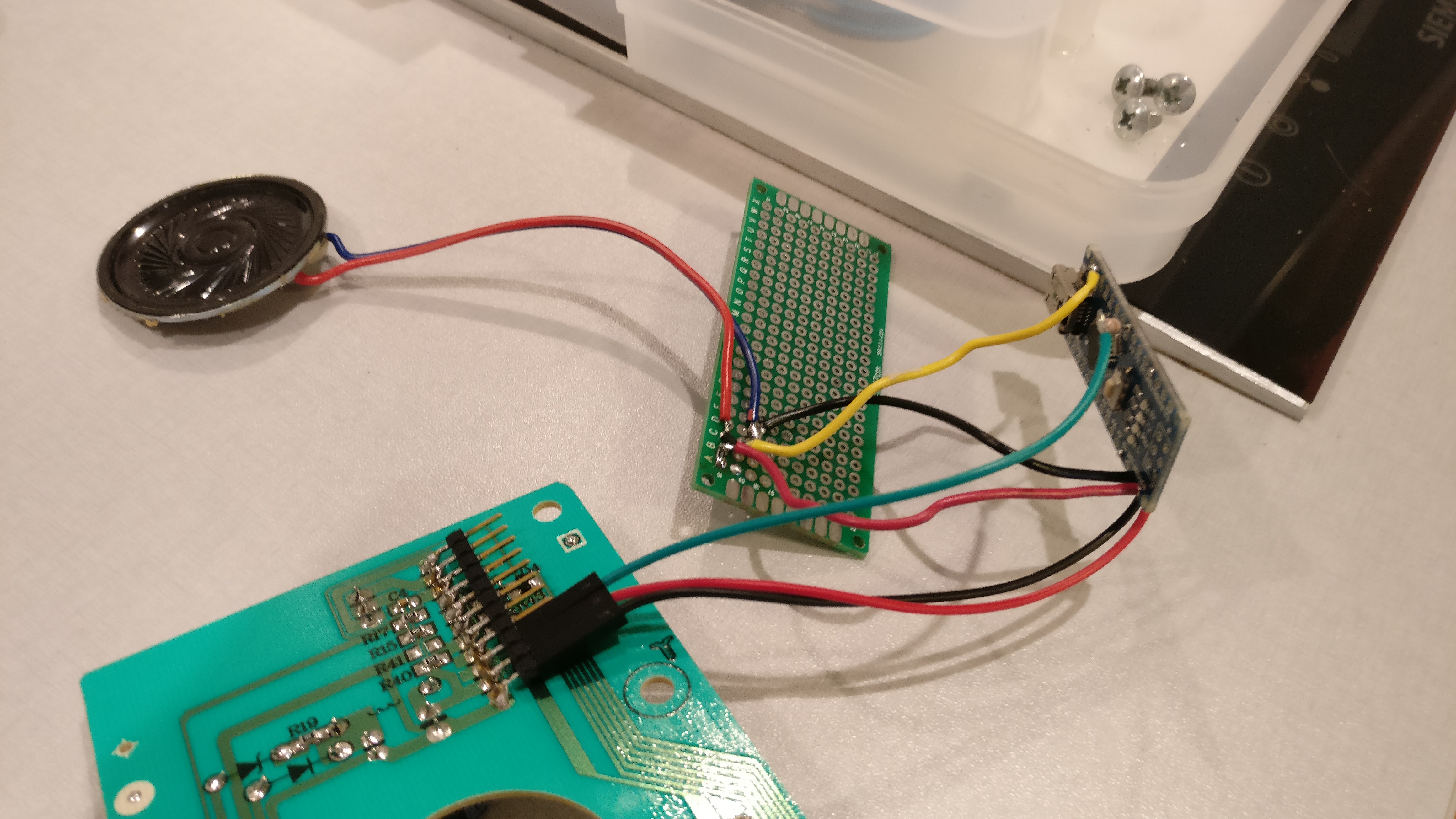
I build a small amplifier out of an MOSFET (IRLML6344) and a small 0.5W speaker element I found at my local hackerspace.
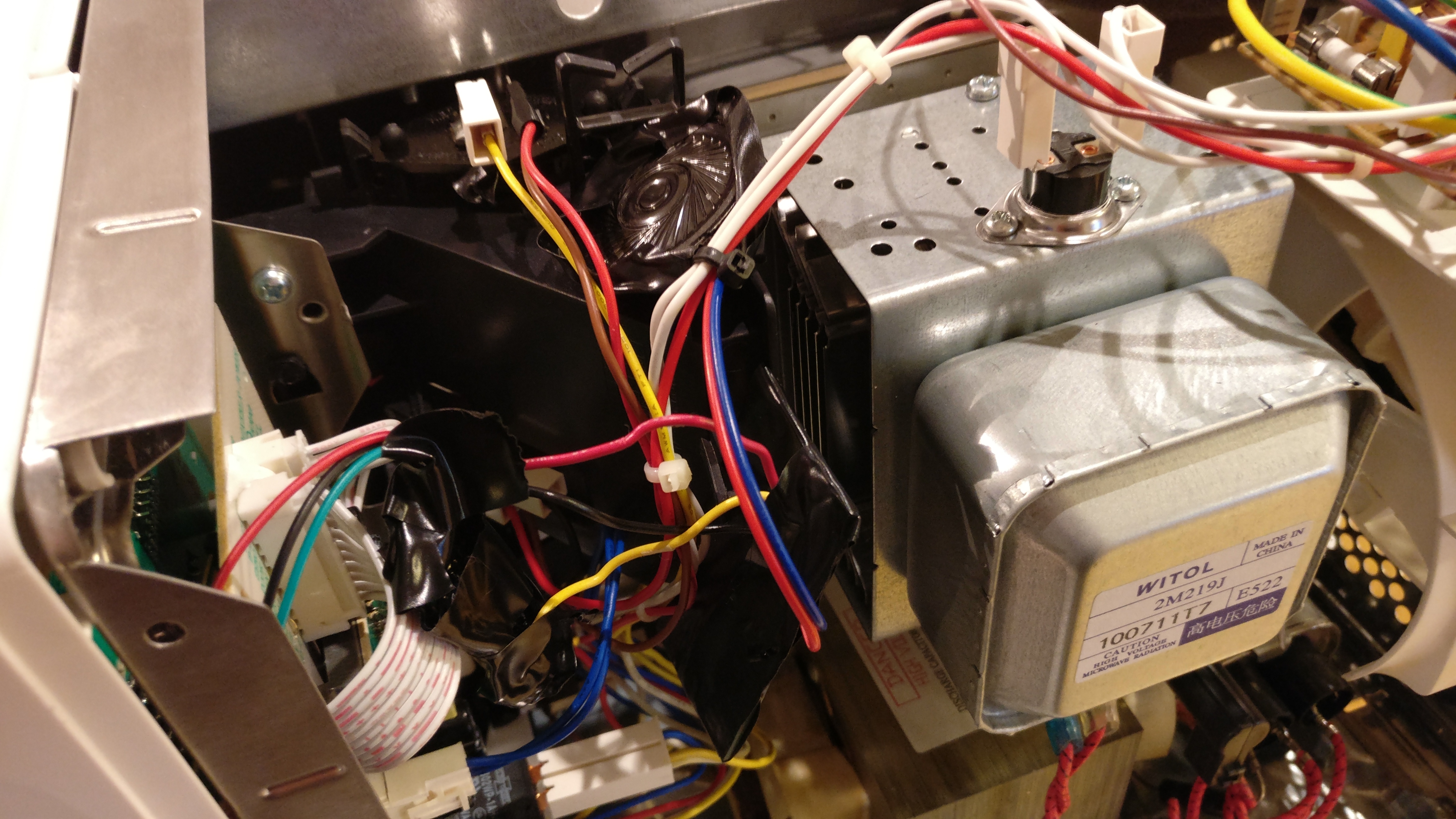
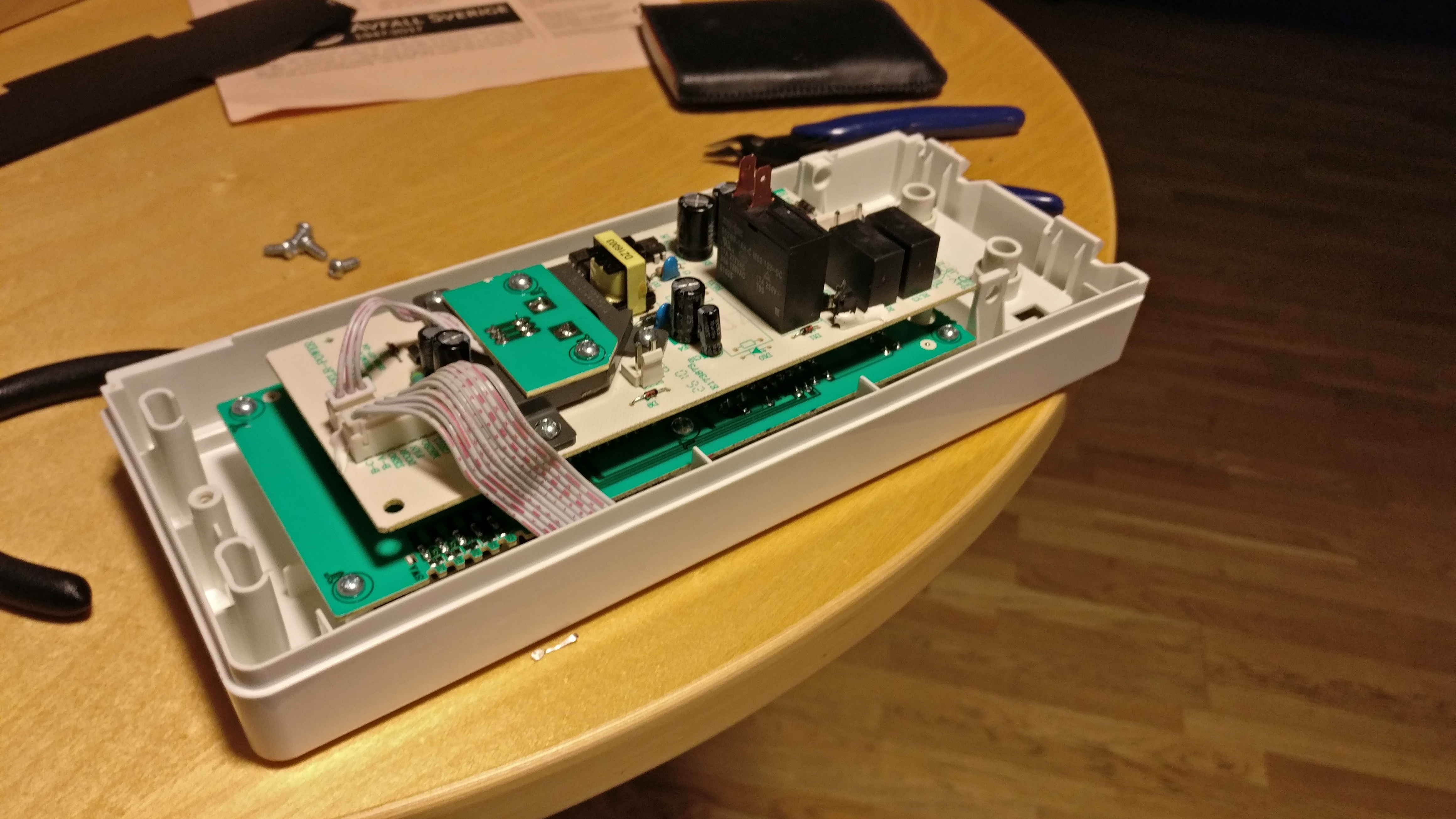
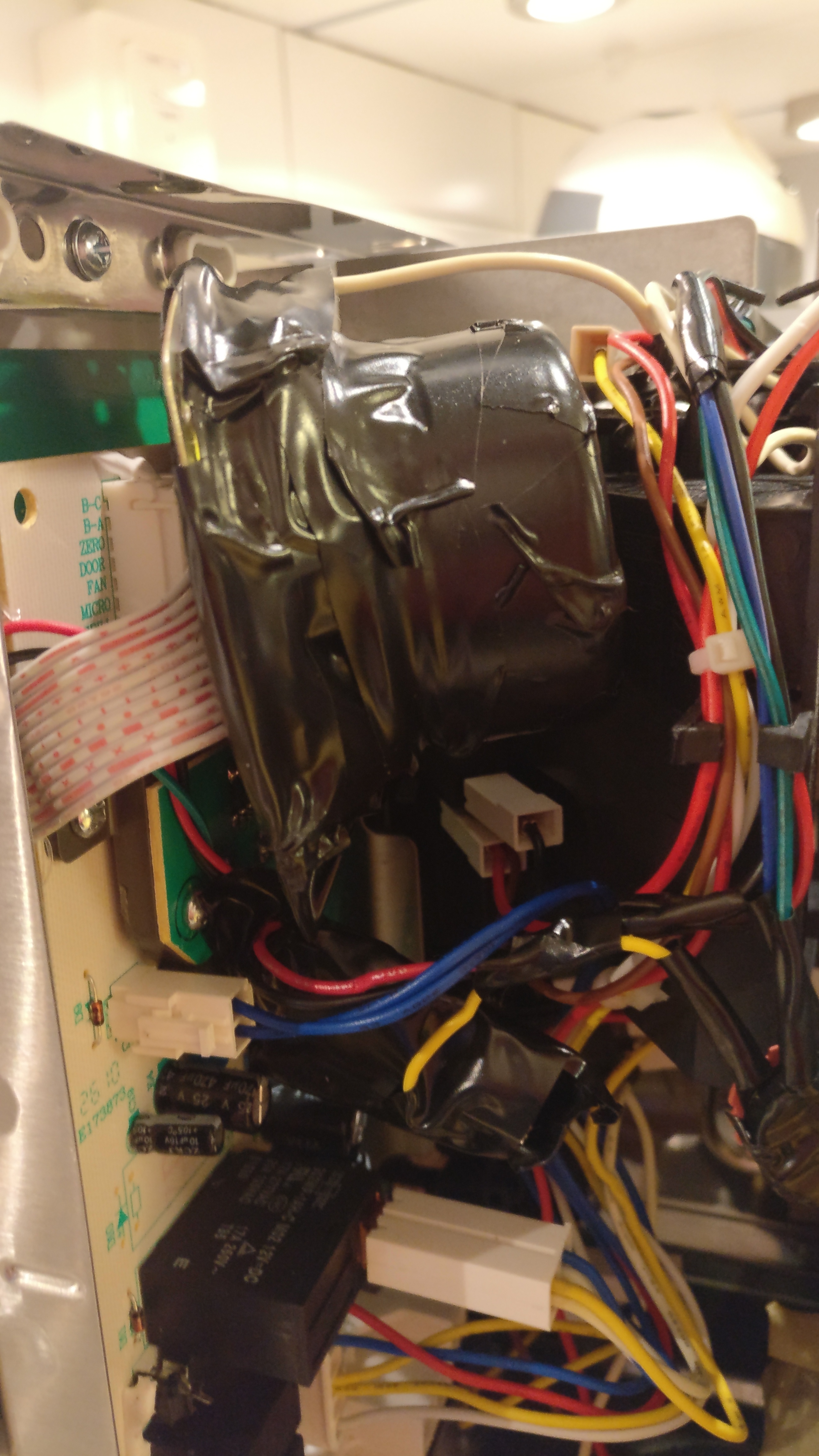
I throw it all into the chassis of the microwave oven. There was plenty of space, but i took some precautions to electrically isolate the PCB and speaker.
Unfortunately the sound from the small 0.5W element was too low. It barely was distinguishable against the sound of the microwave ovens fan.
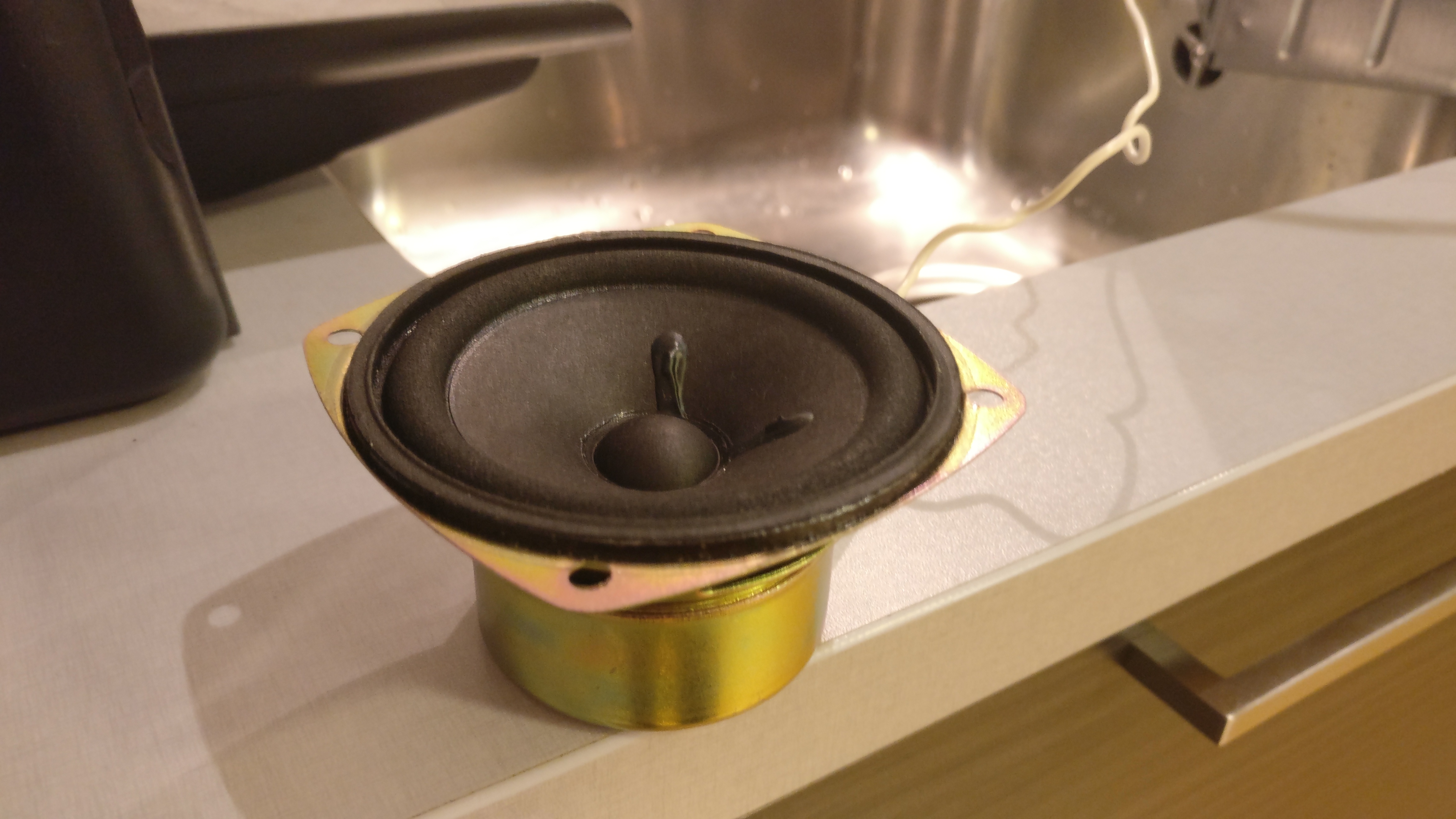
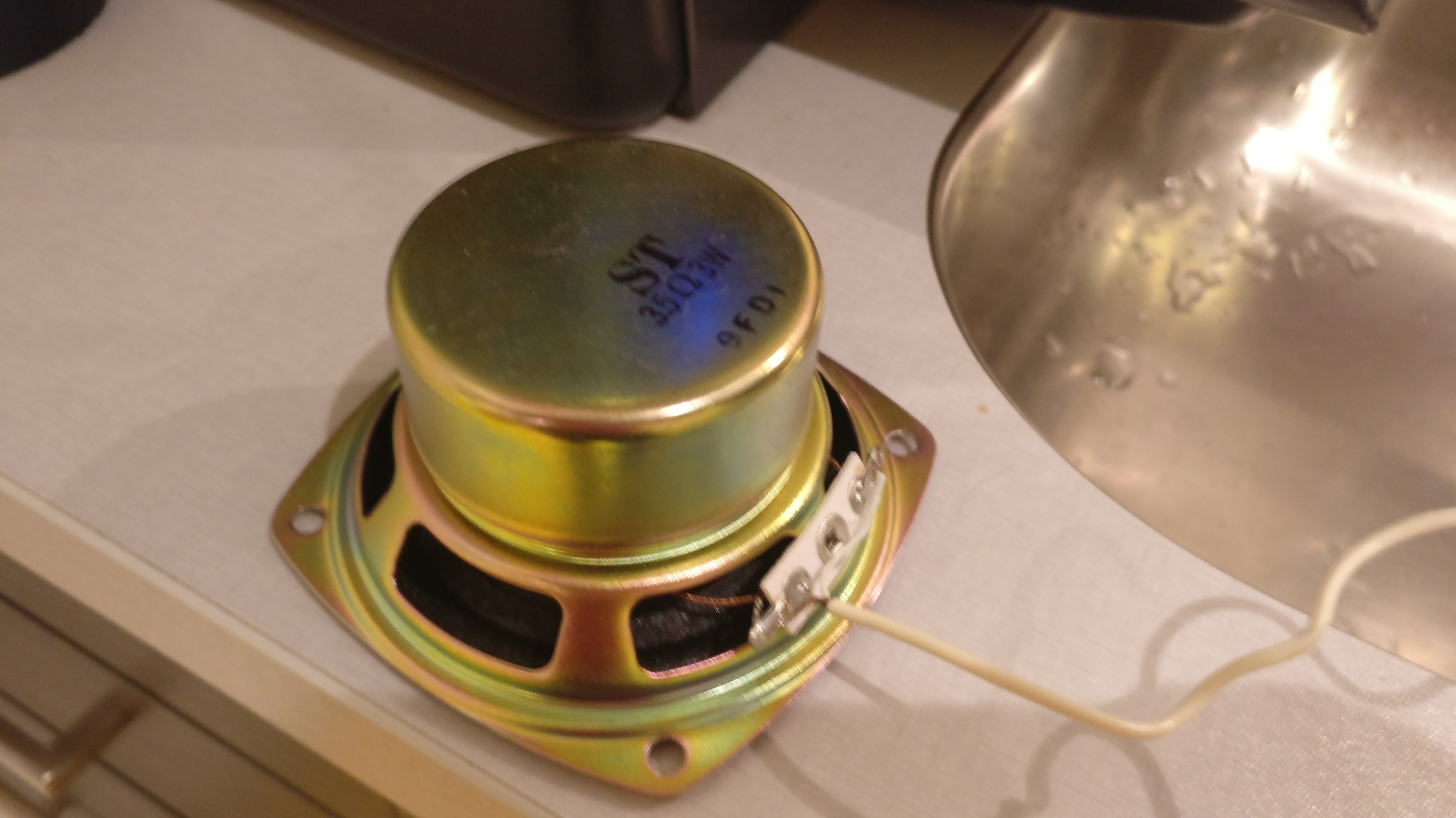
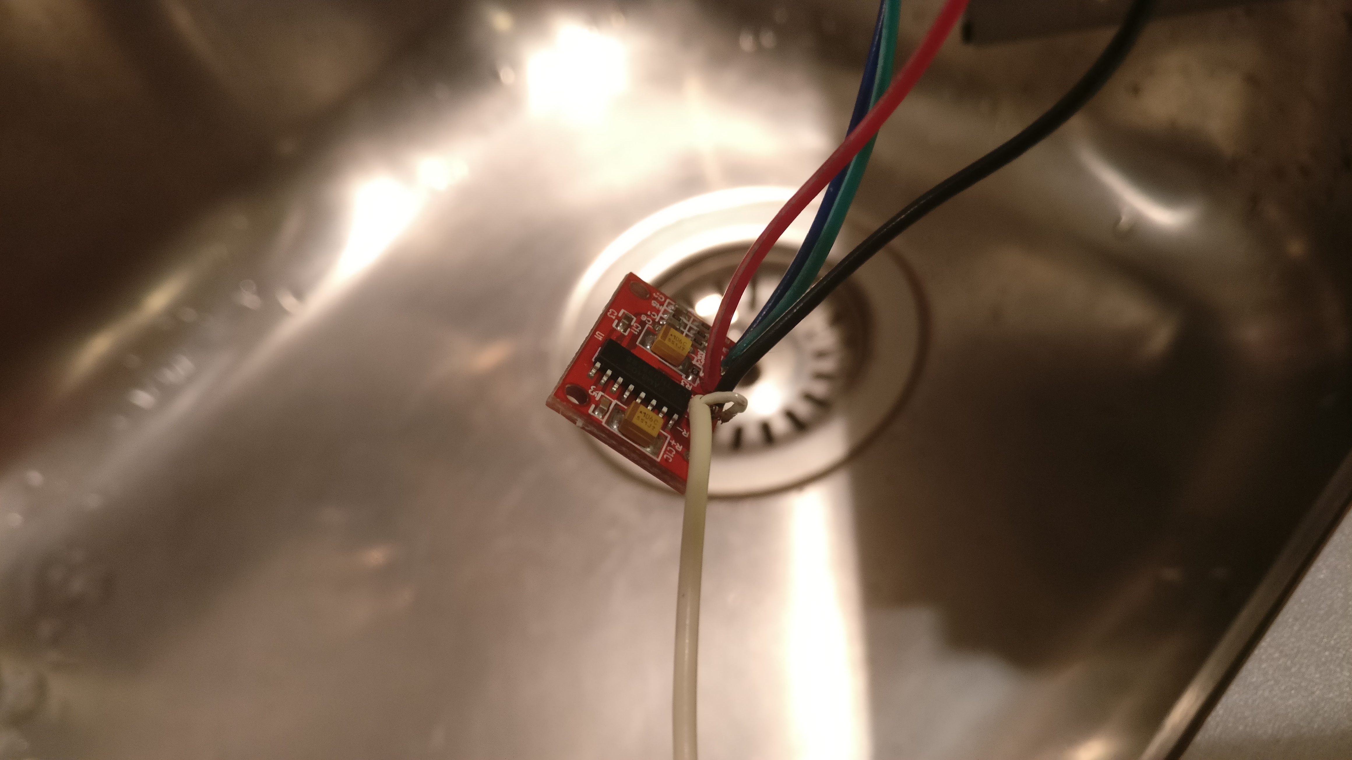
So I upgraded the element for a 3W element that I found in an old PC speaker, and took some precautions and upgraded my amplifier as well for the more stable Class-D amplifier PAM8403.
The sound was much louder and you can clearly hear the “Done”-sound from the microwave oven.
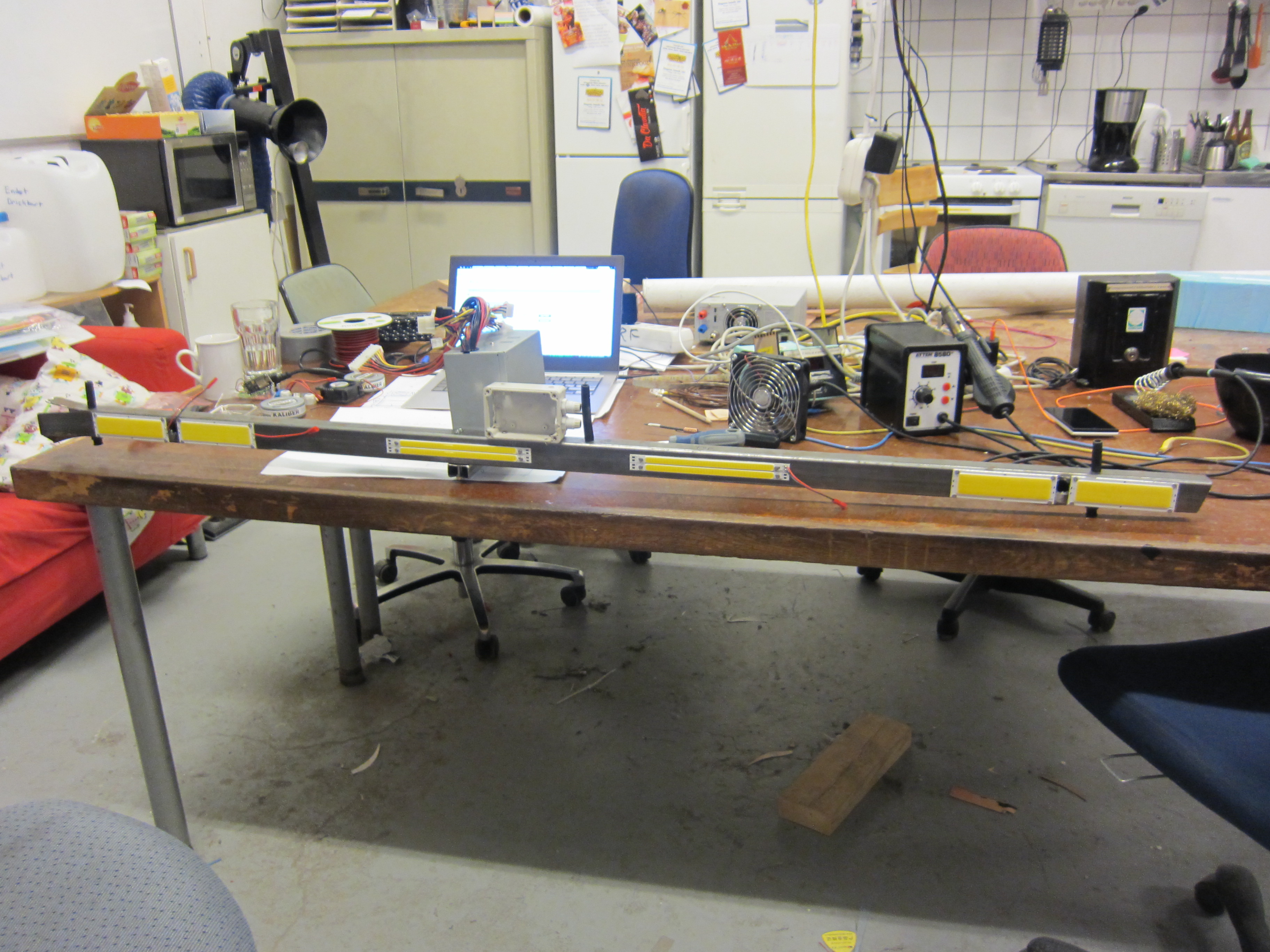
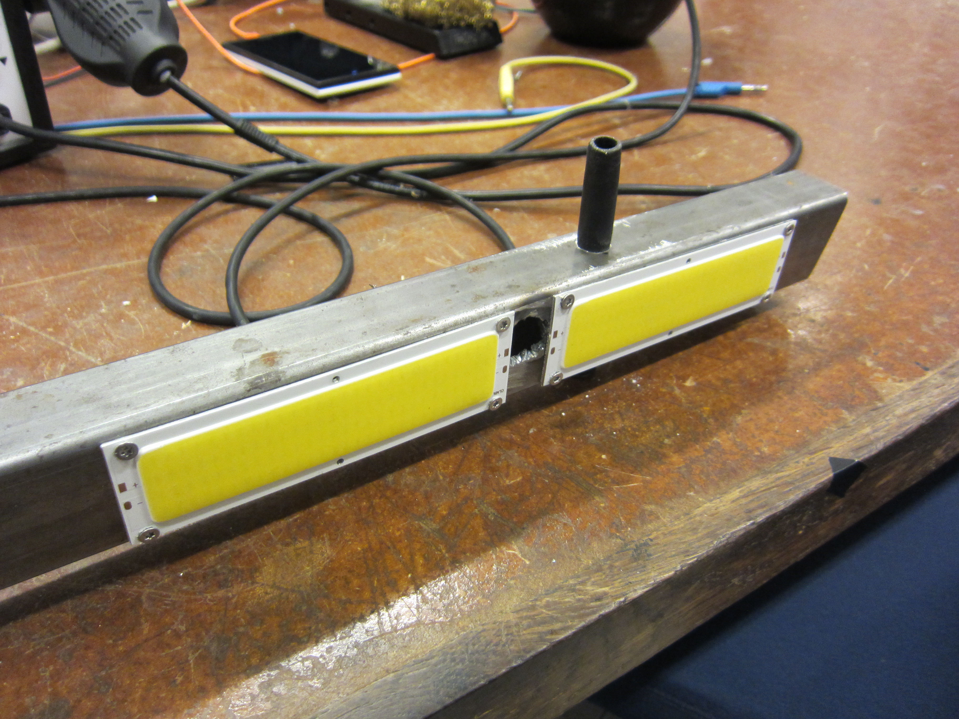
This flashbar, aka blinder, was used under a concert to give a blinding effect for the audience.
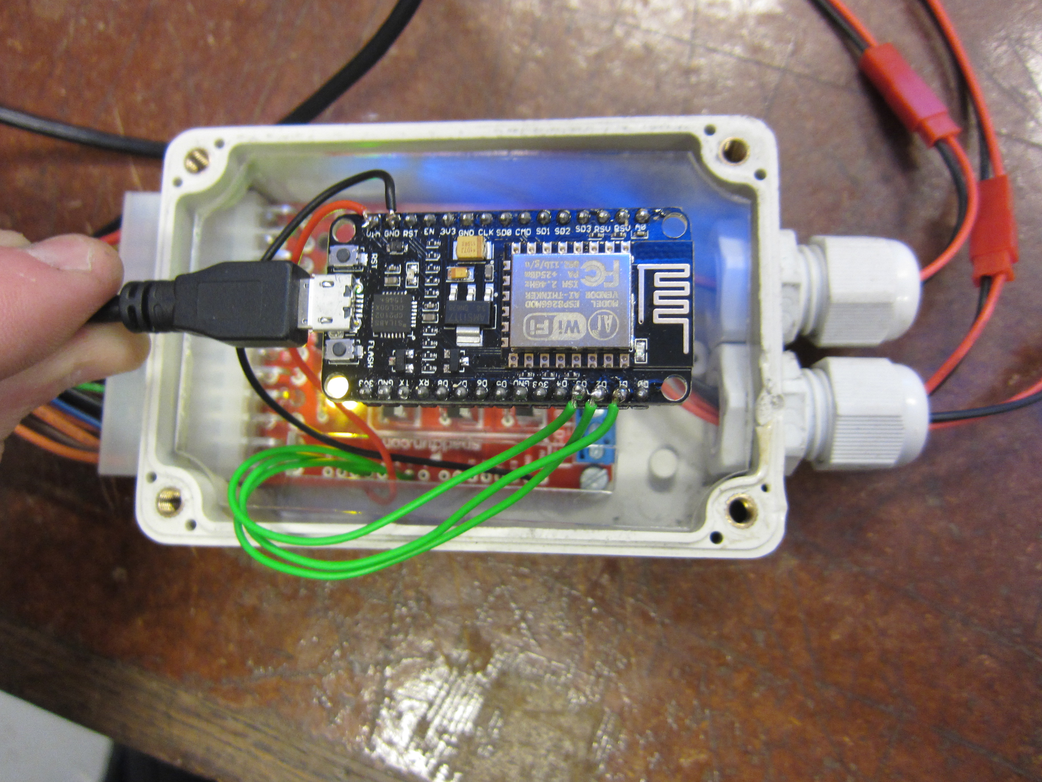
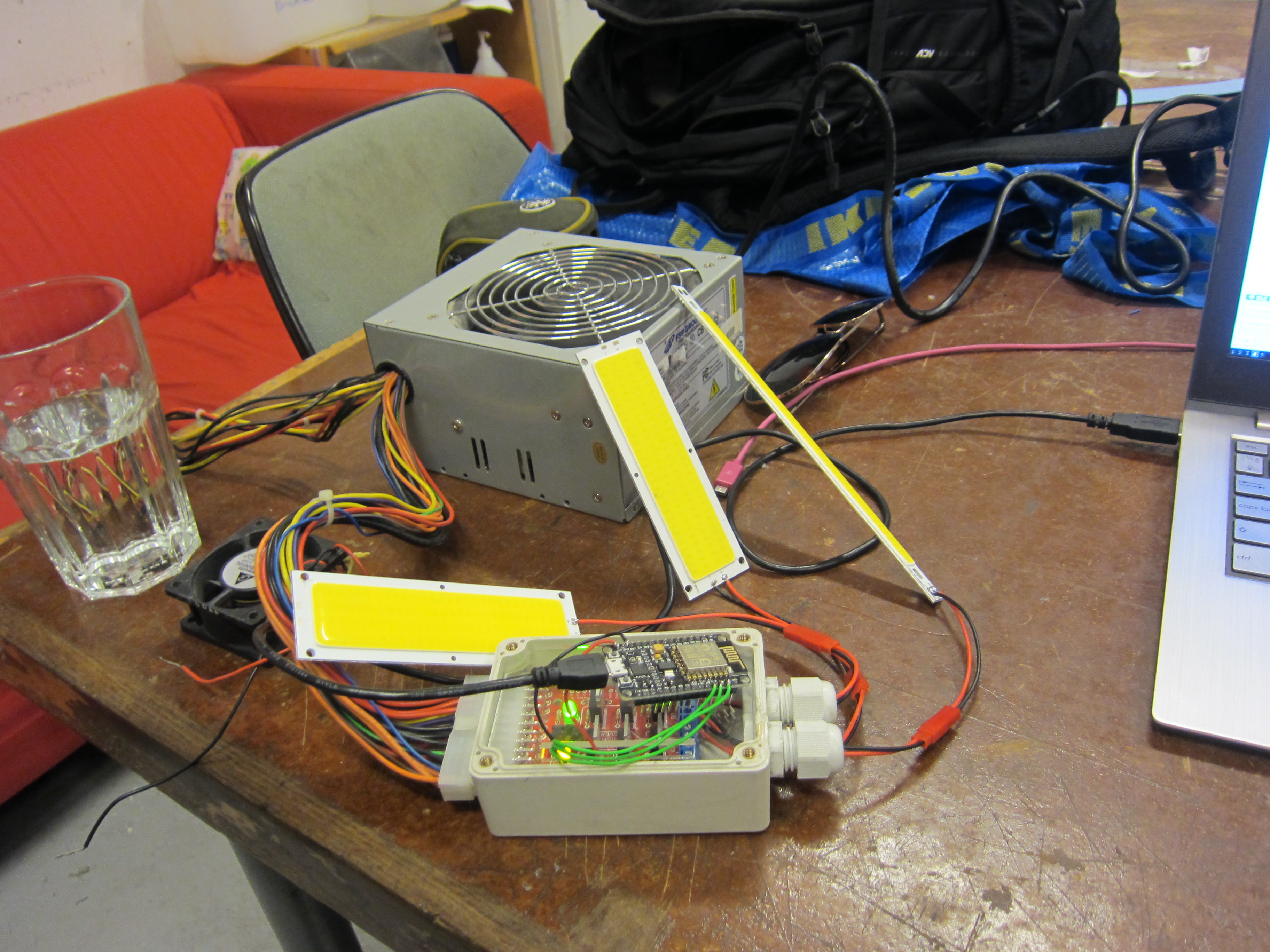
A mosfet driver is enabling the LED’s. The LED’s is 10W element, and there is 8 elements on the flashbar giving 80W of power.
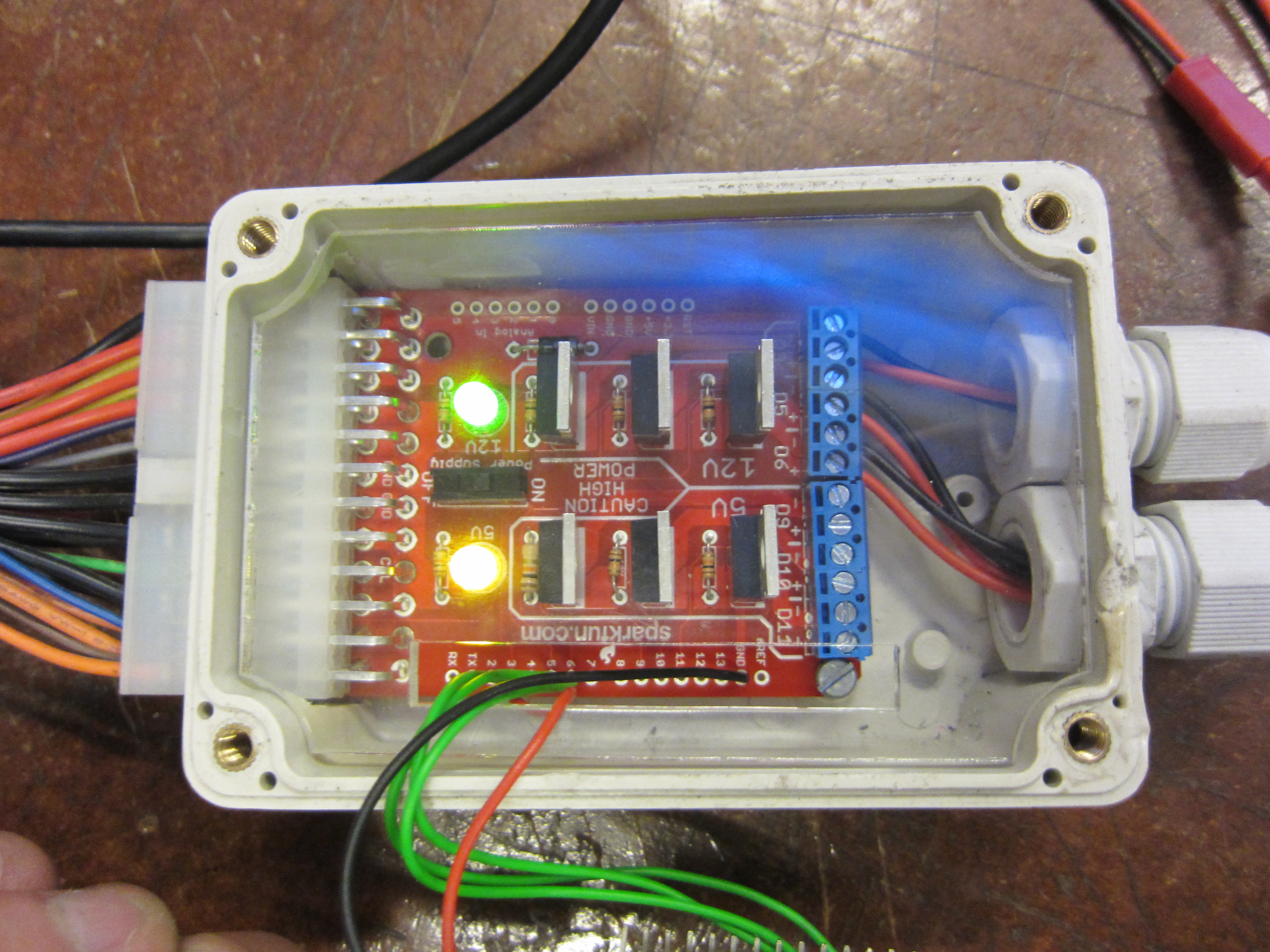
It’s powered from an PC power supply.
The ESP8226 is running a small UDP server and listens for sACN packets. sACN is like DMX512, but over UDP instead of RS-485.
You can find the firmware here https://github.com/TimGremalm/FlashBar.
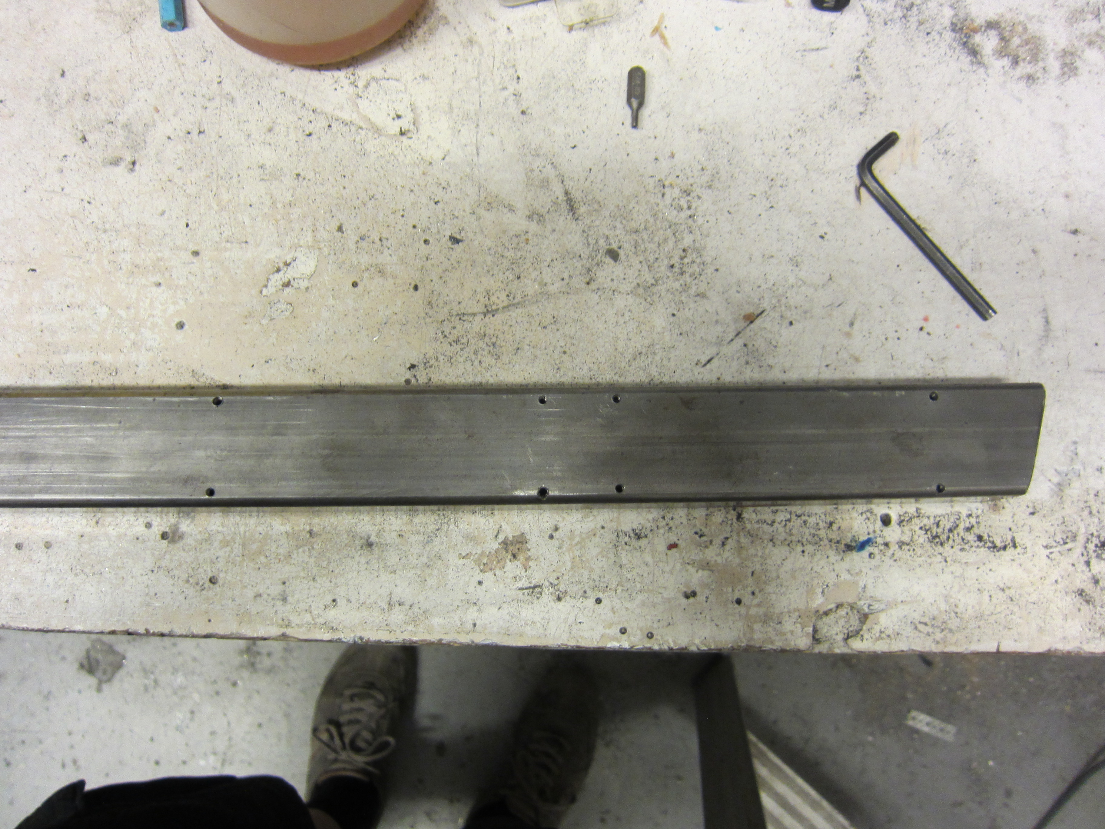
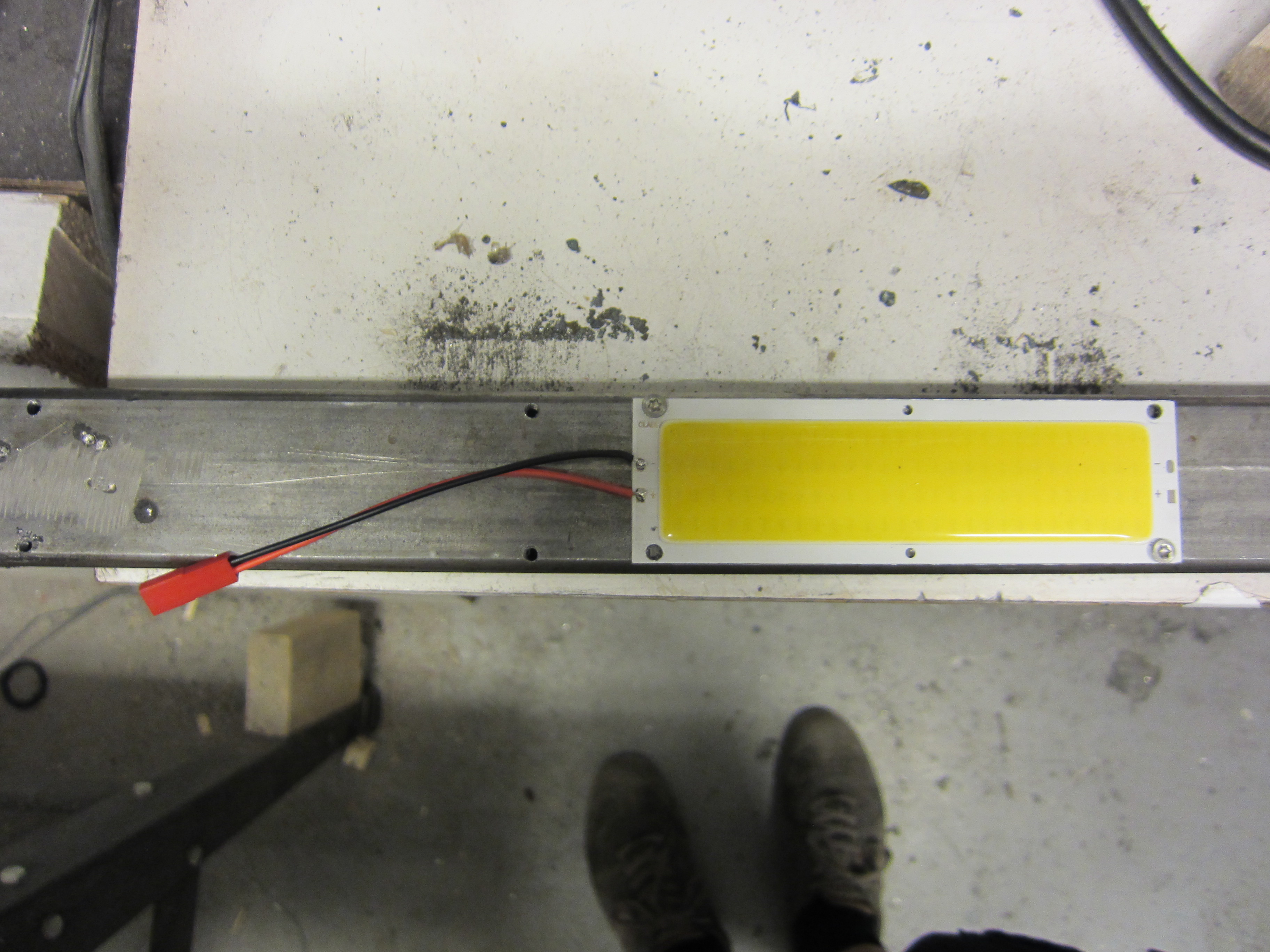
The LED’s are screwed down on top of a steel bar to transfer the heat.
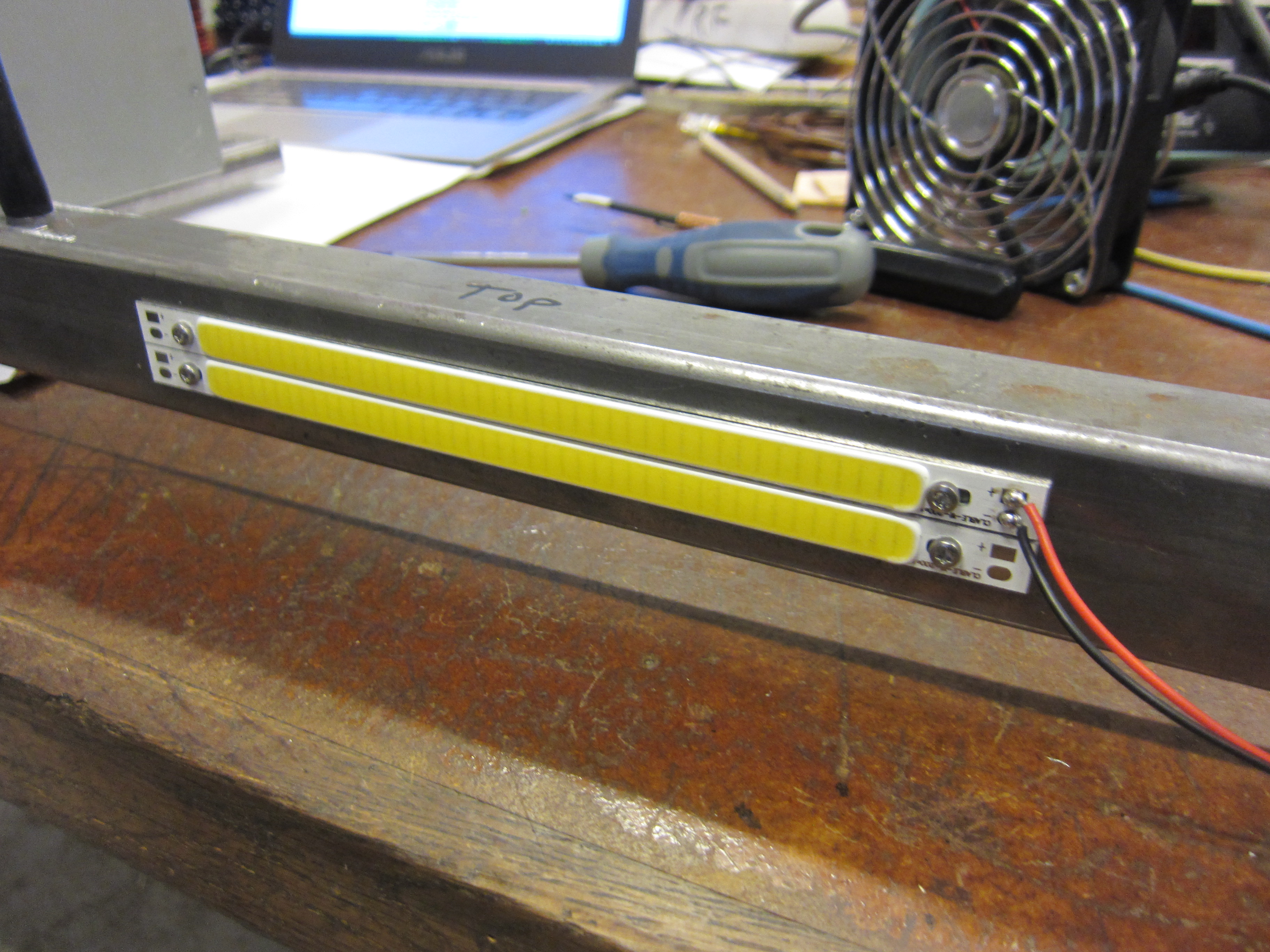
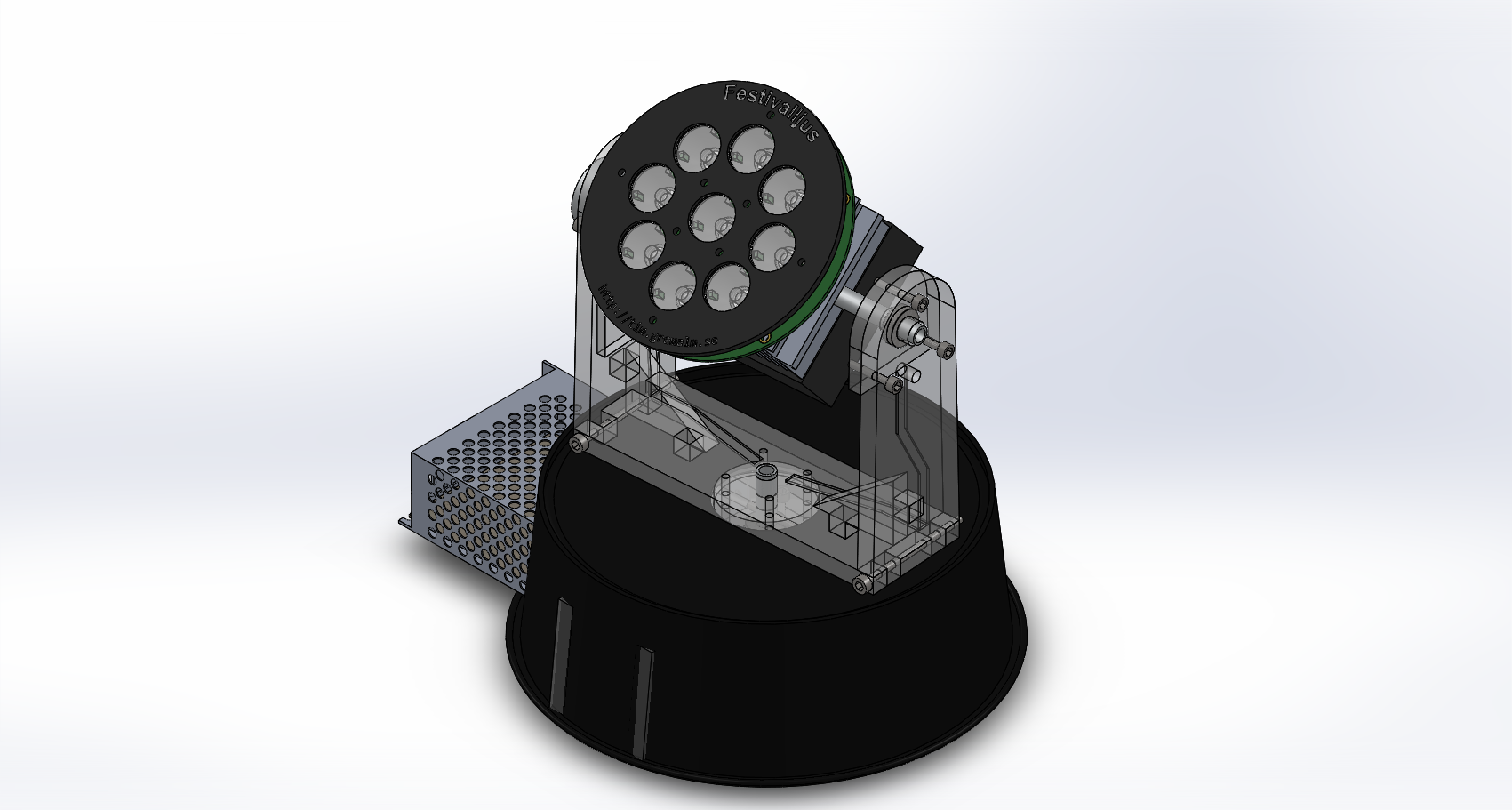
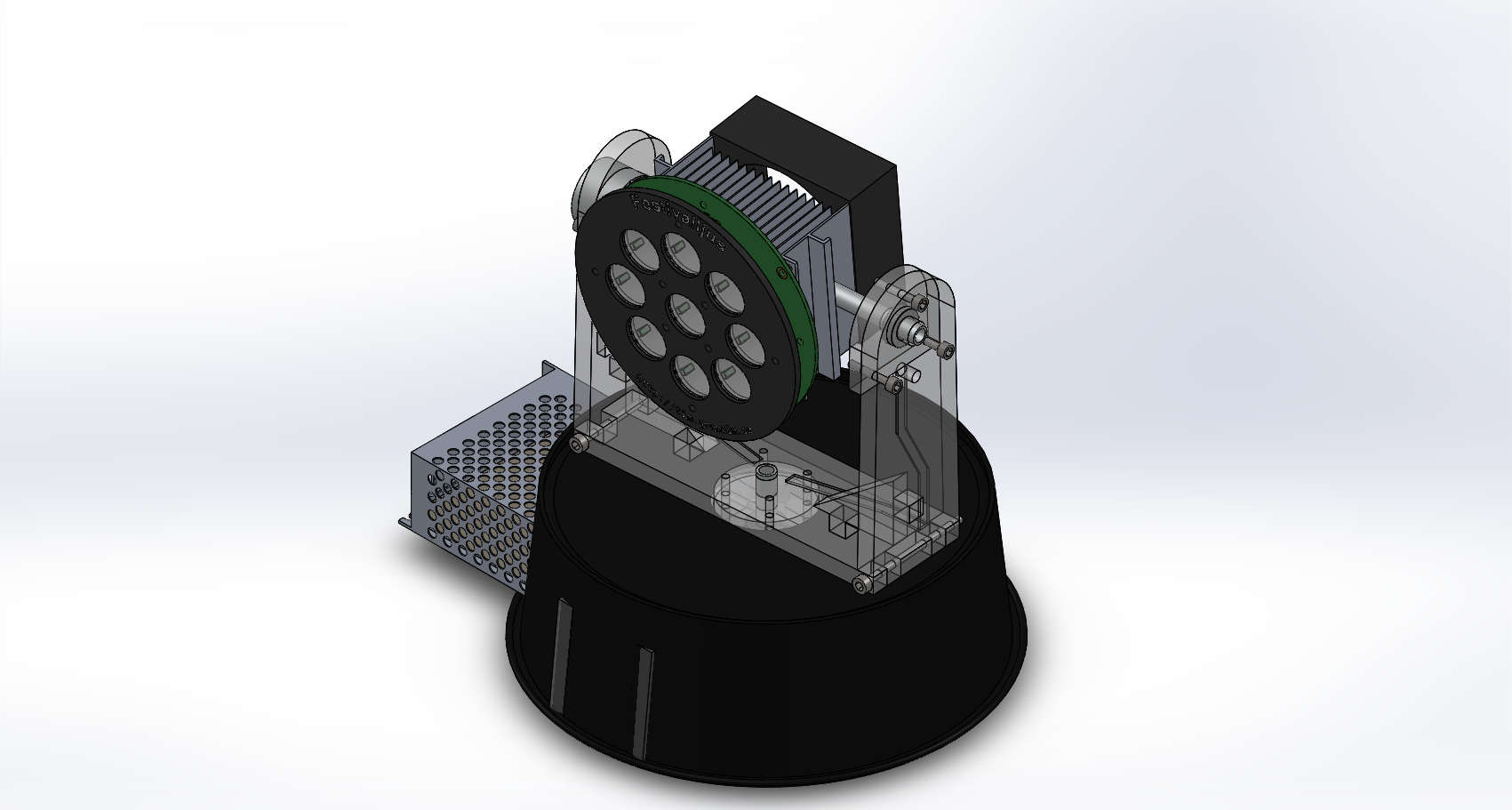
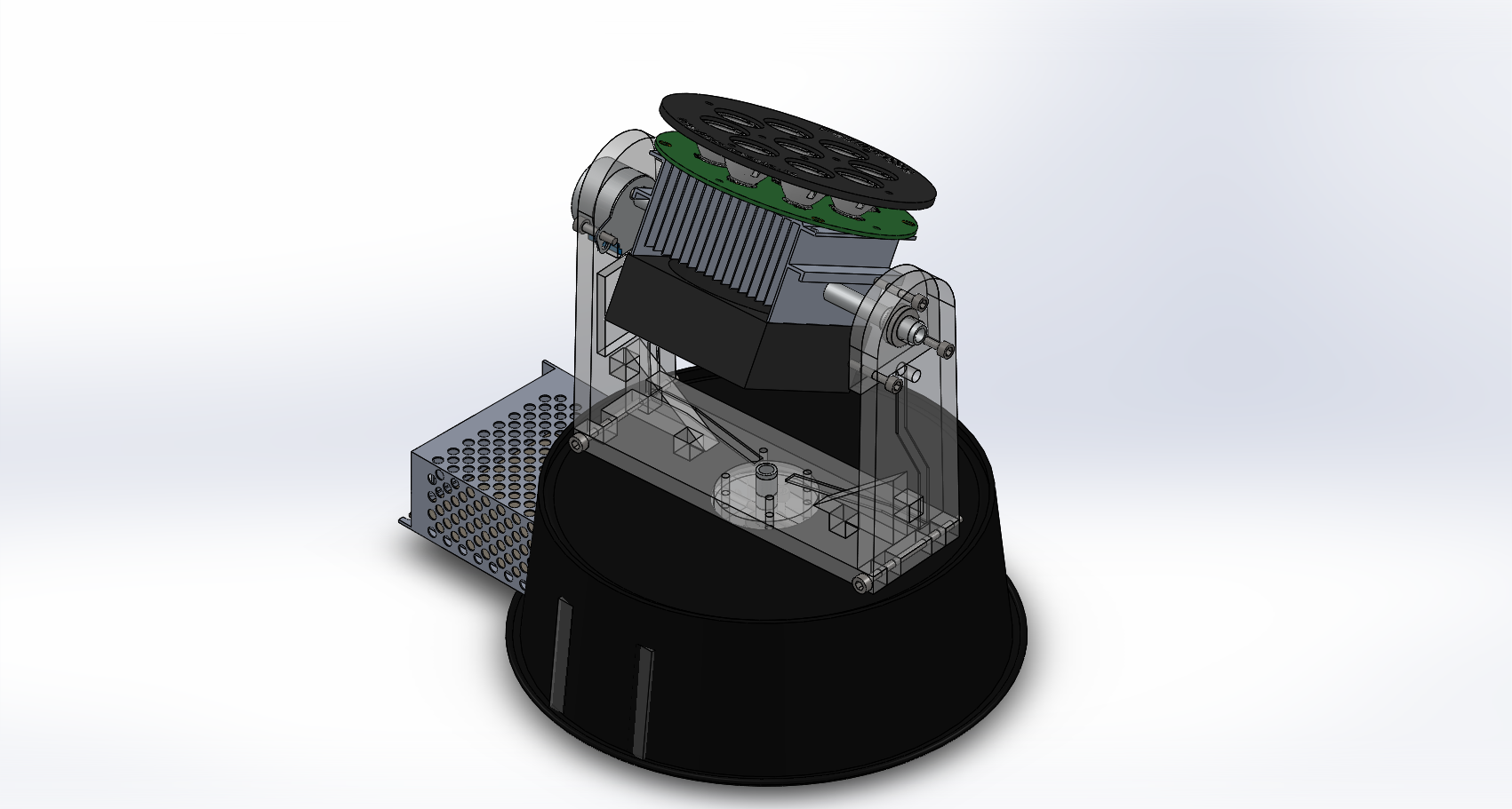
One of the hardest things with this project is to solve the problem with the heating. 9 pieces of 3W LED tends to get very hot, 27W that have to be transferred to the air.
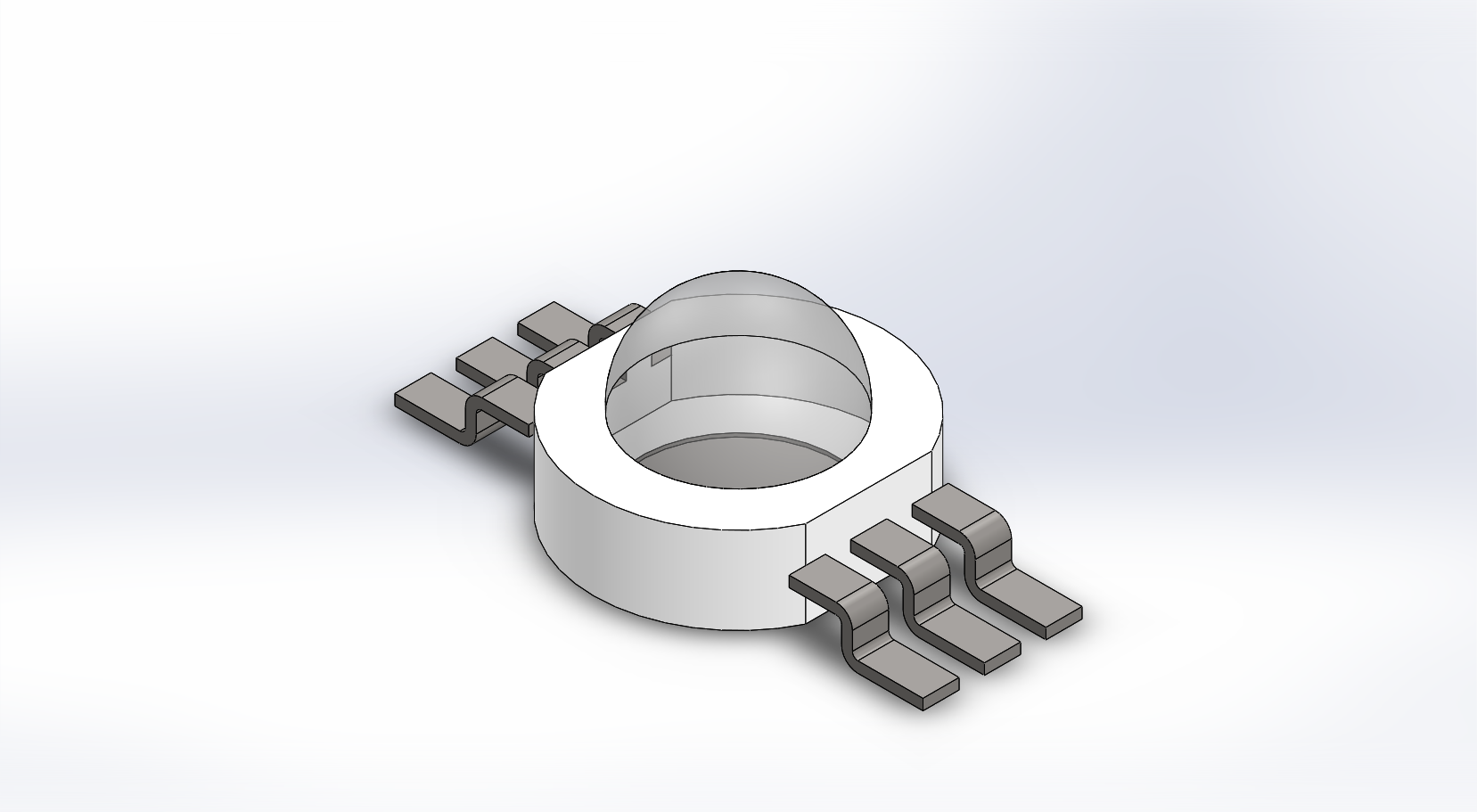
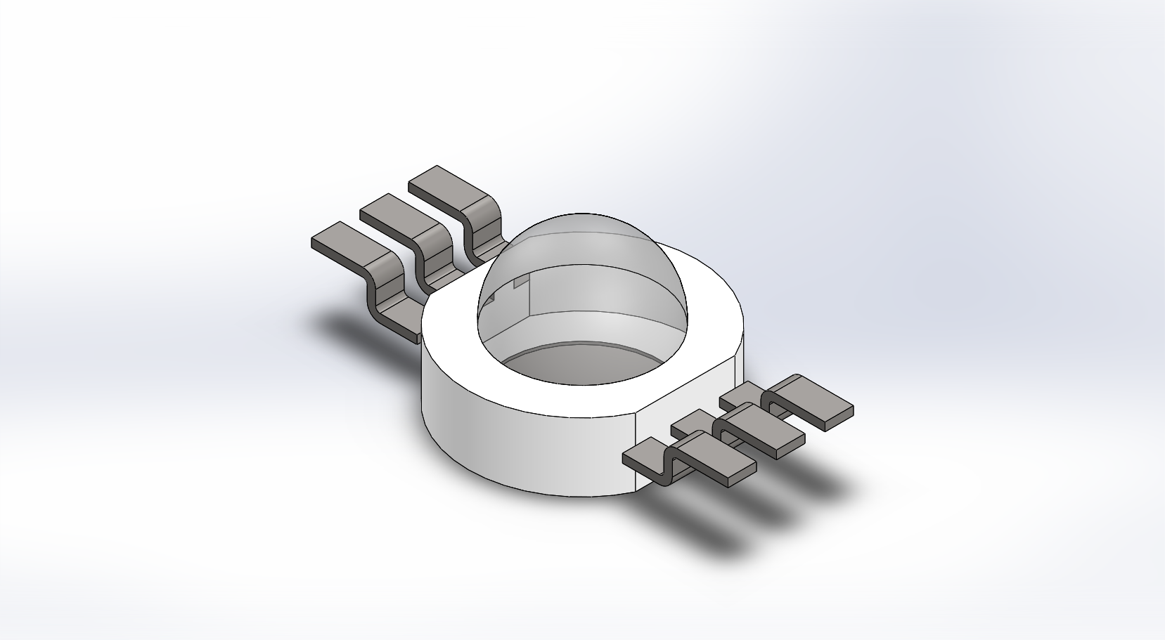
If I bend the pins on the led I can make the LED’s go through the PCB. An alternative is to use a lot of small via’s under the LED to transfer the heat to the underside. But I think a direct contact with the heatsink will be more effective.
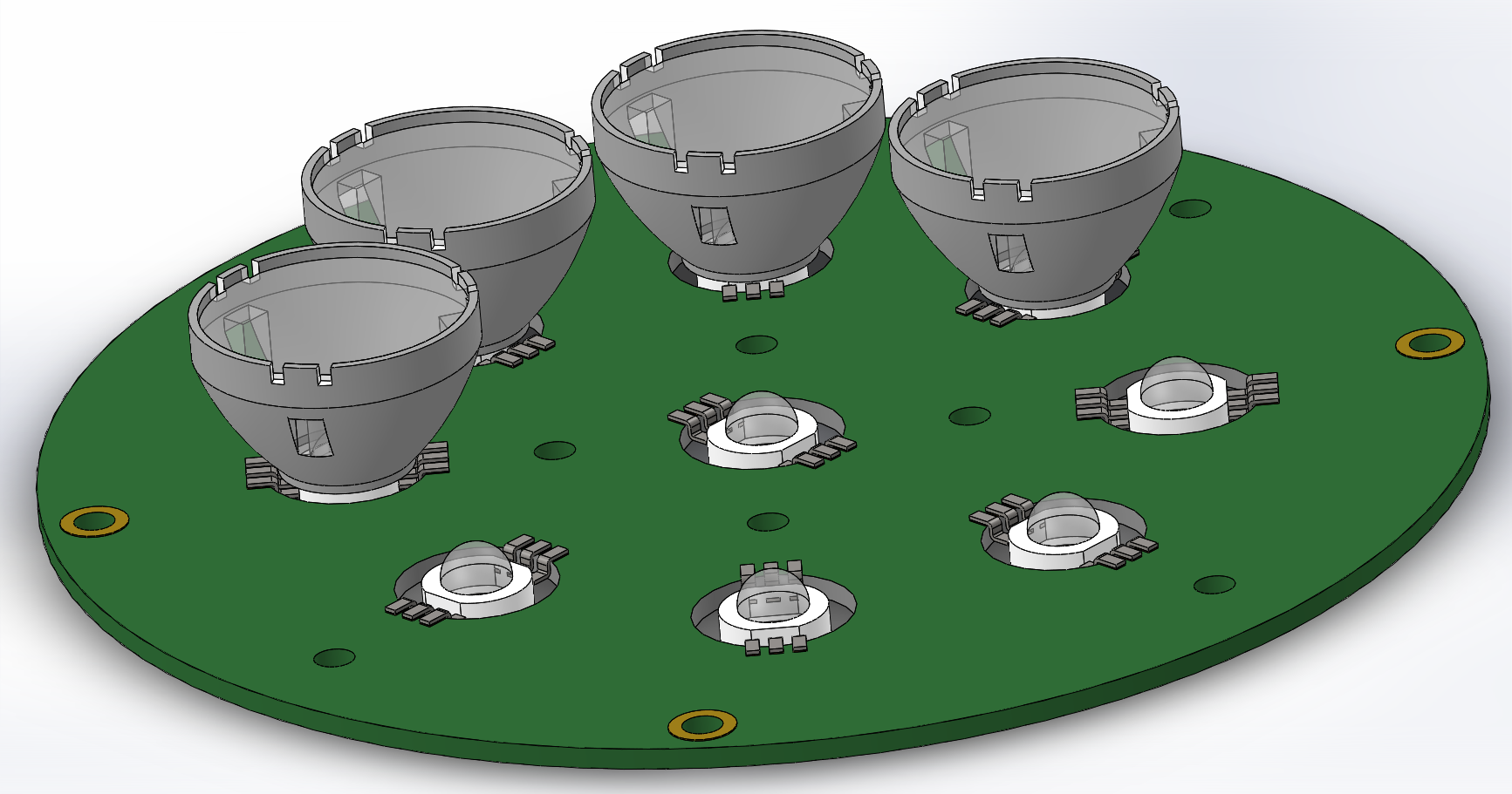
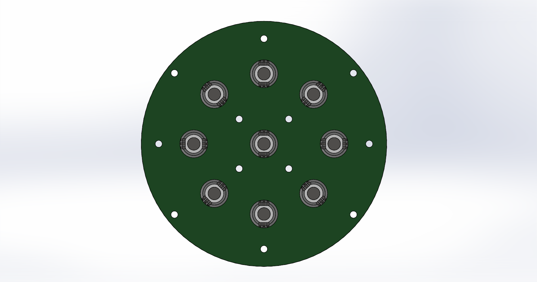
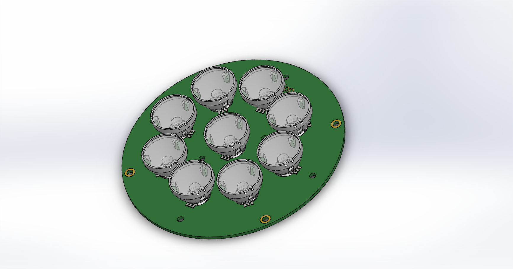
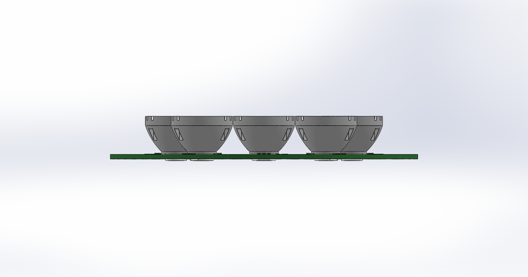
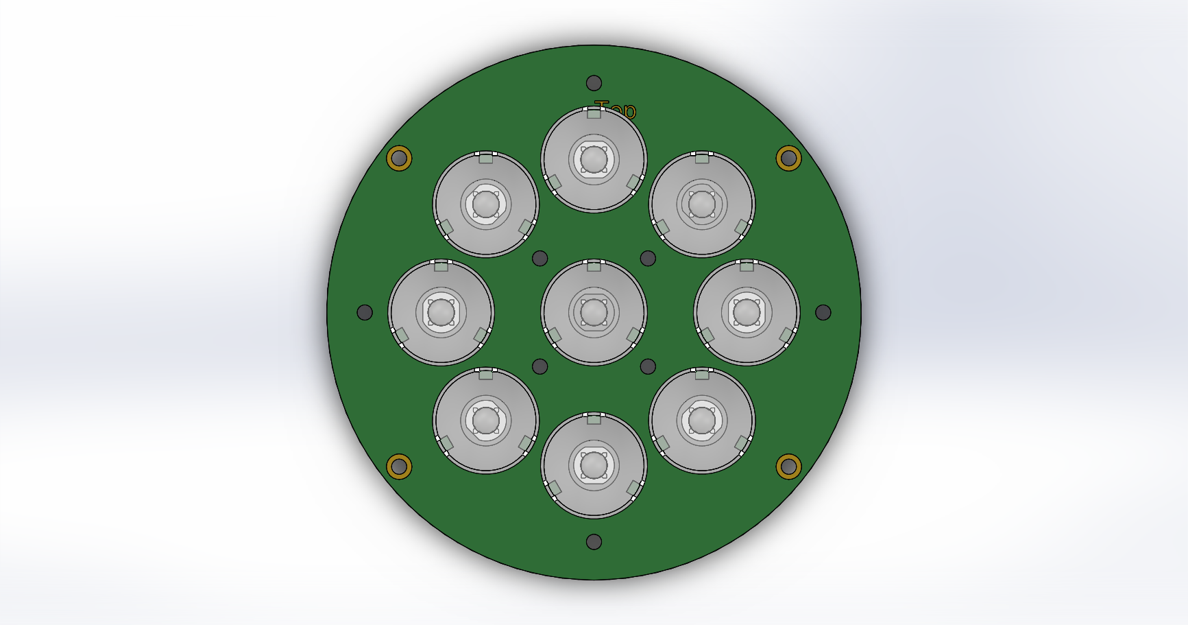
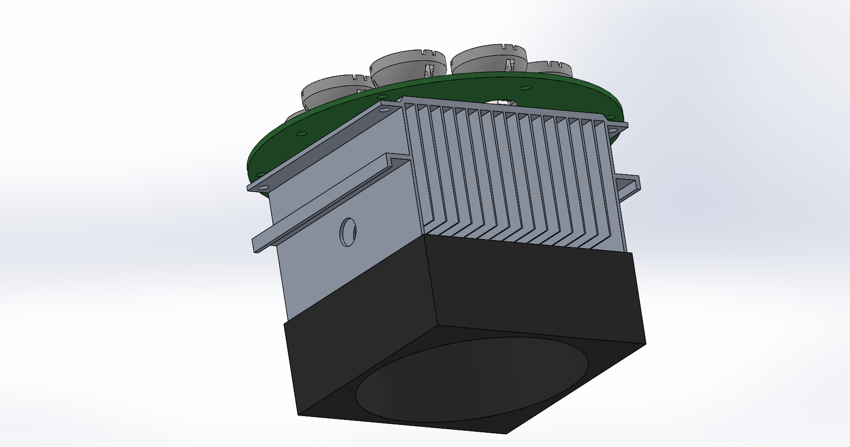
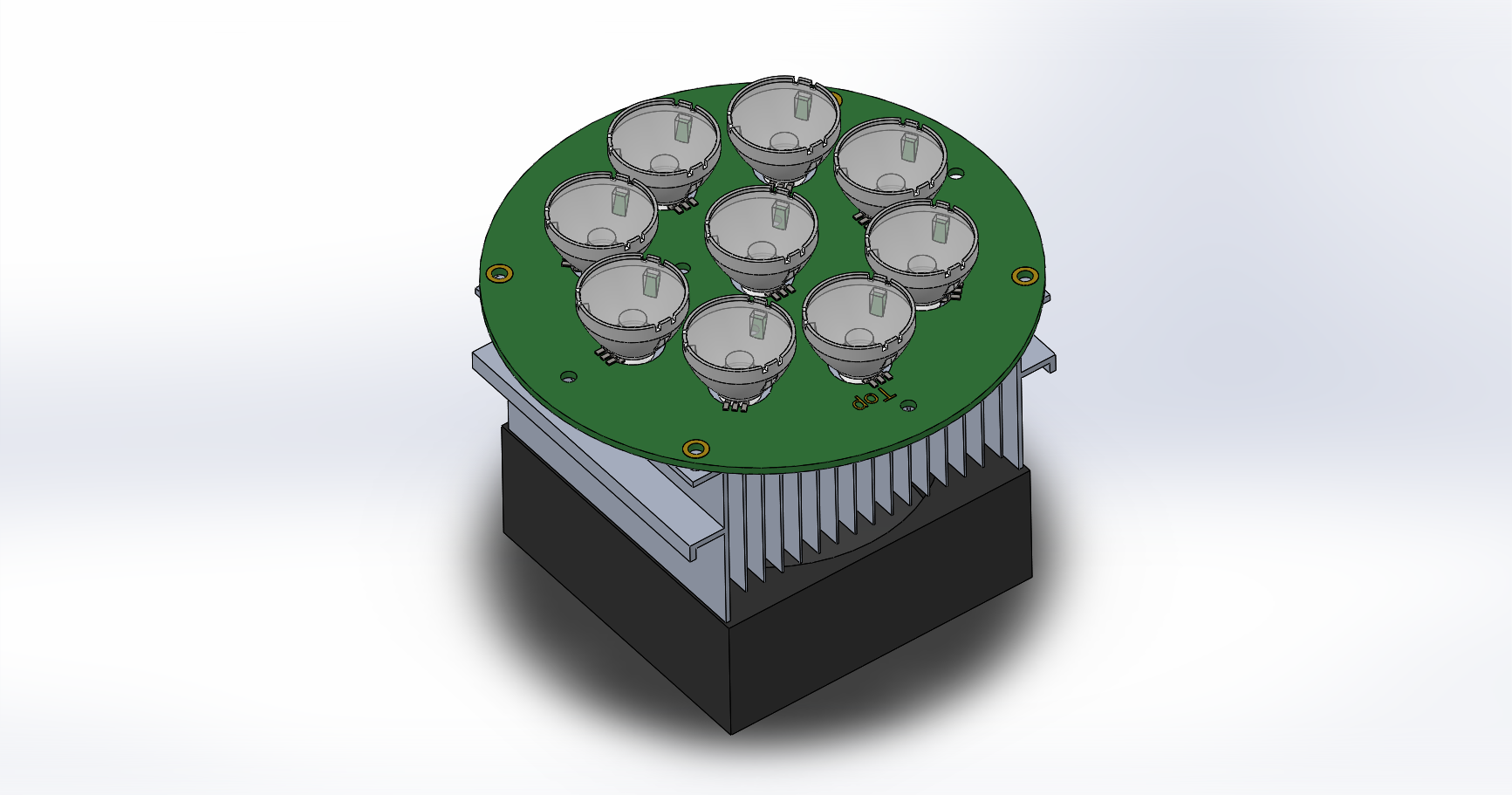
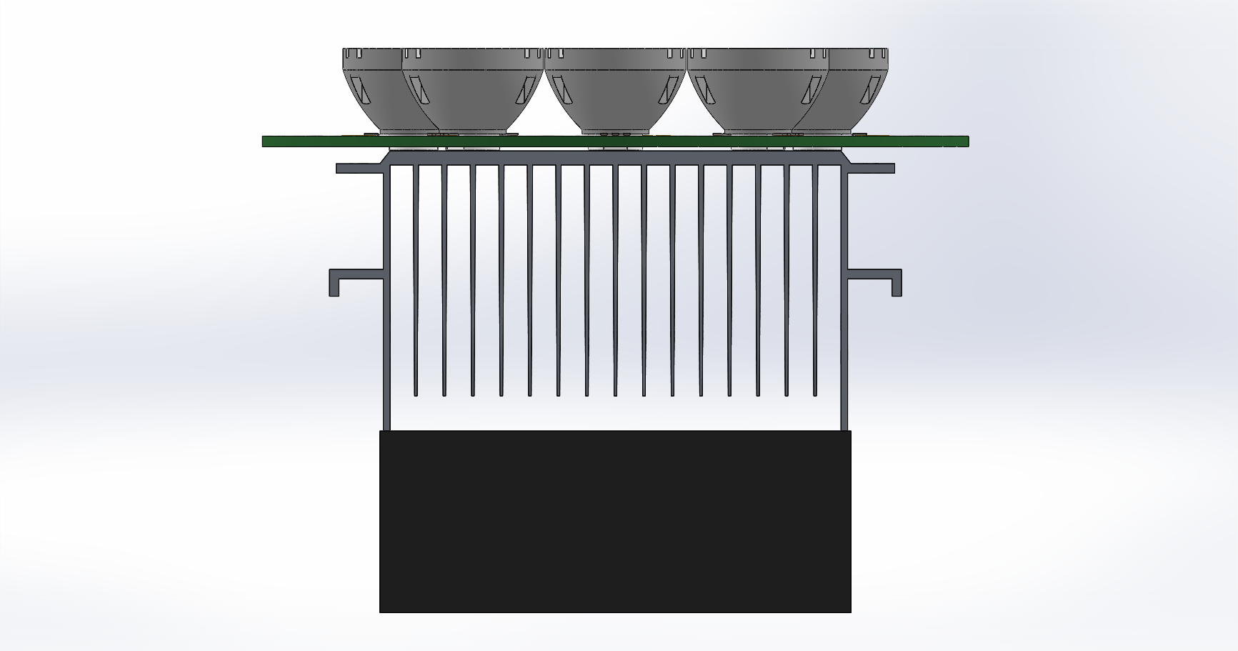
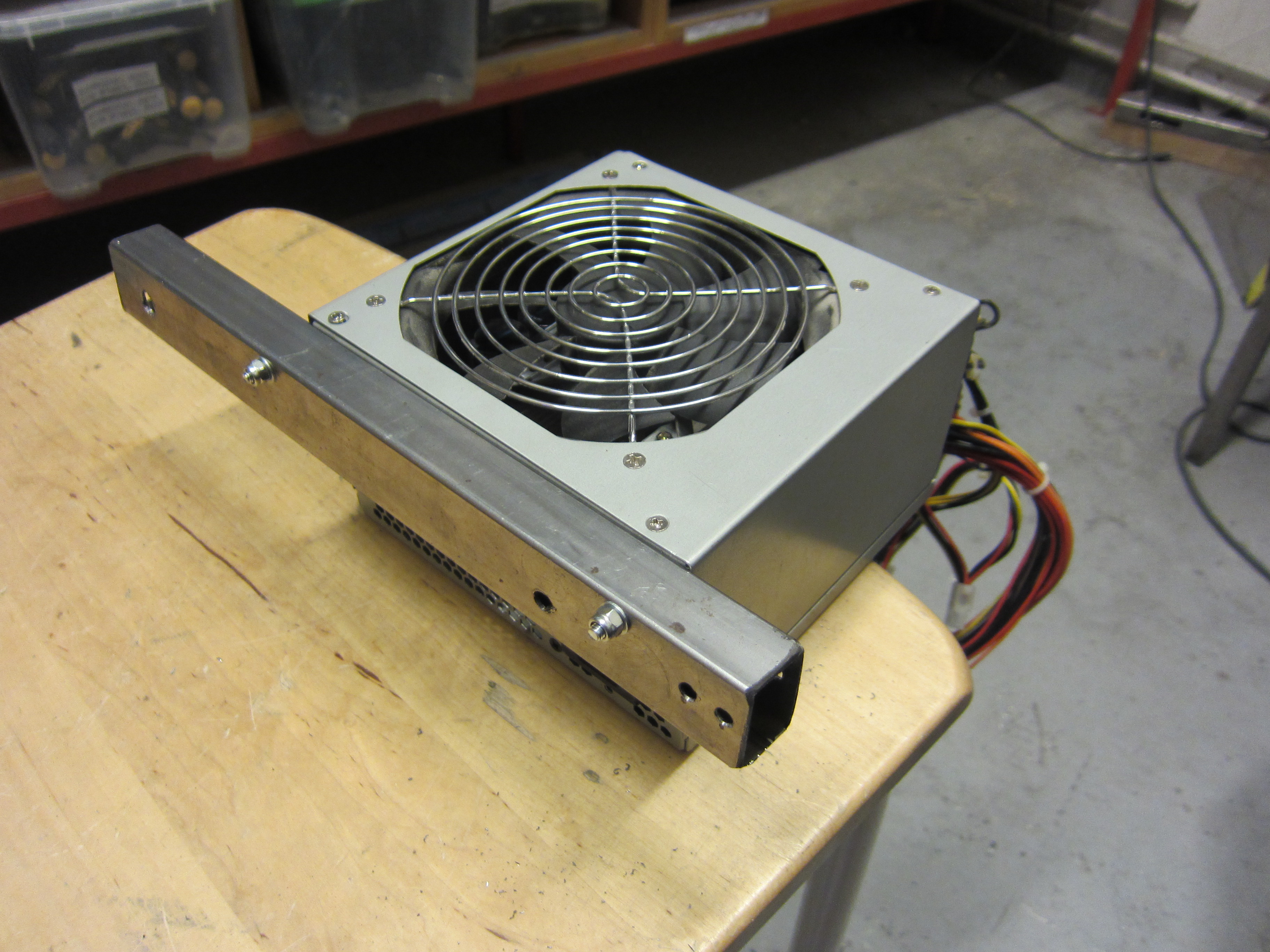
A CPU cooler should be sufficient enough to transfer the heat out to the air. I don’t know if the fan is necessary.
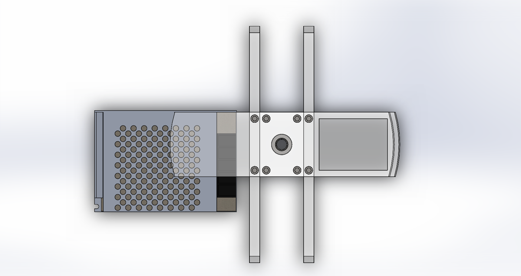
The whole assembly will look something like this:

Optics Specification
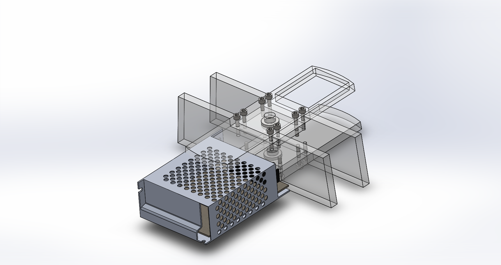
A 12V 5A (60W) switched powersupply will be used for Festivalljus. http://www.ebay.com/itm/181719390201
60W will give a lot of headroom for the 30W LED it’s designed for.
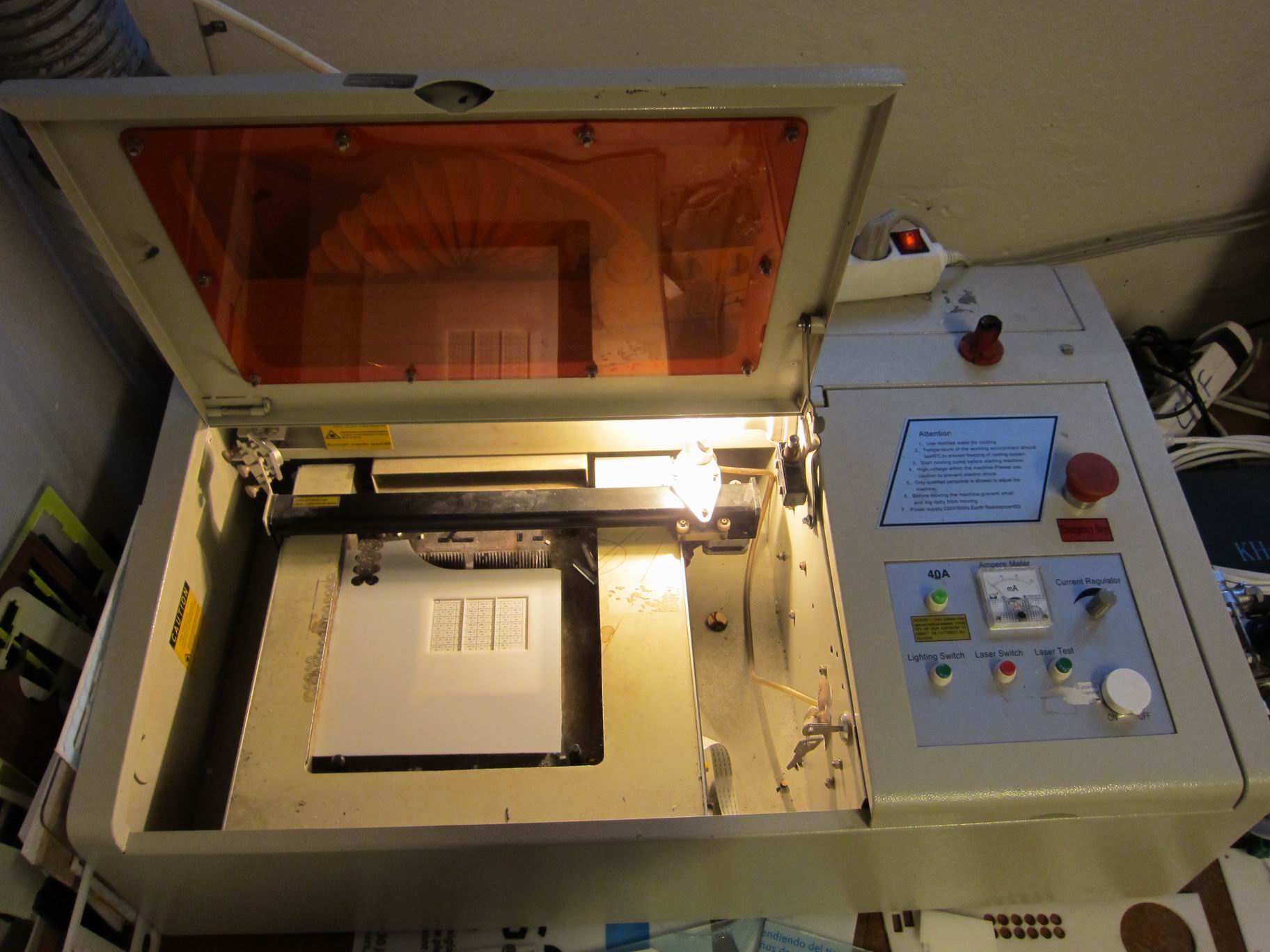
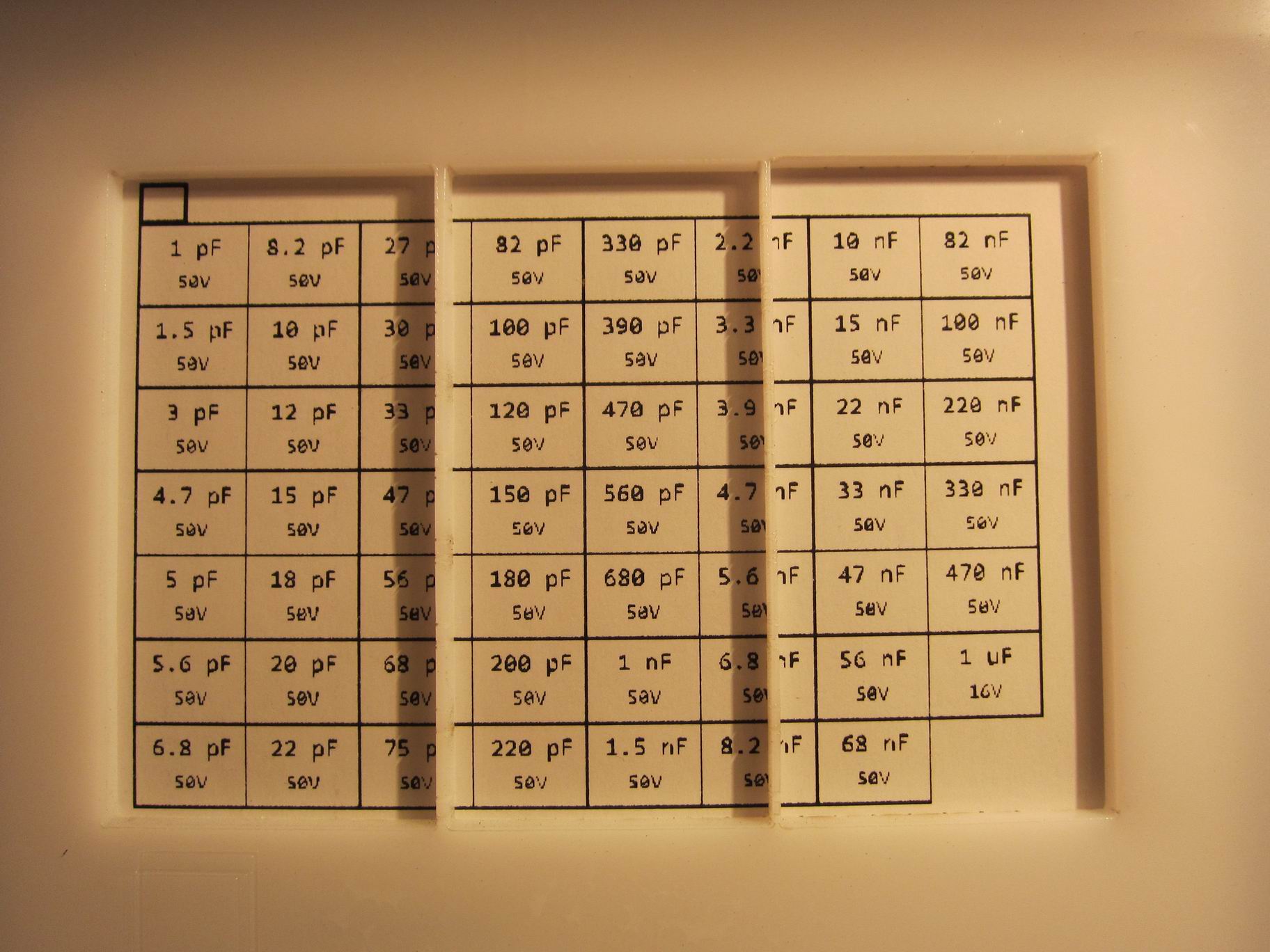
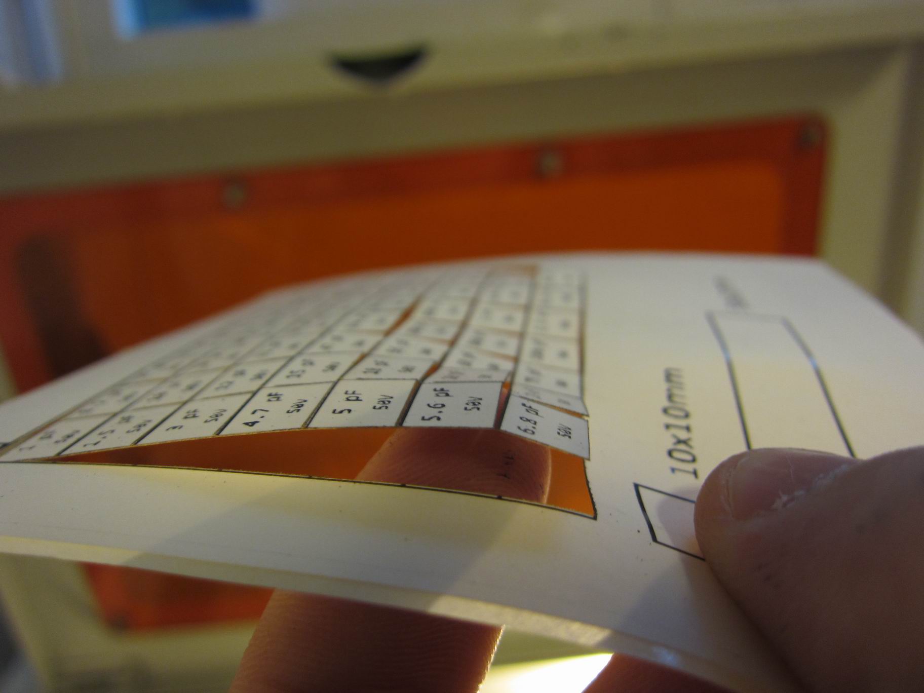
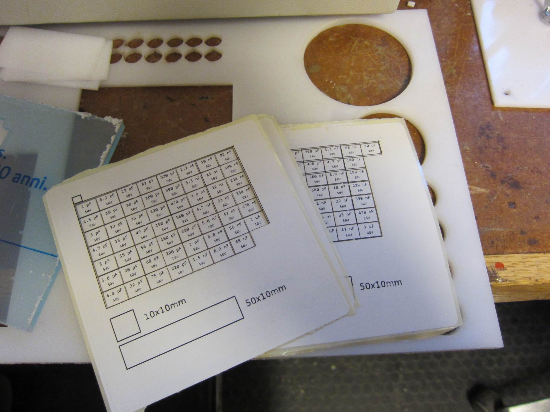
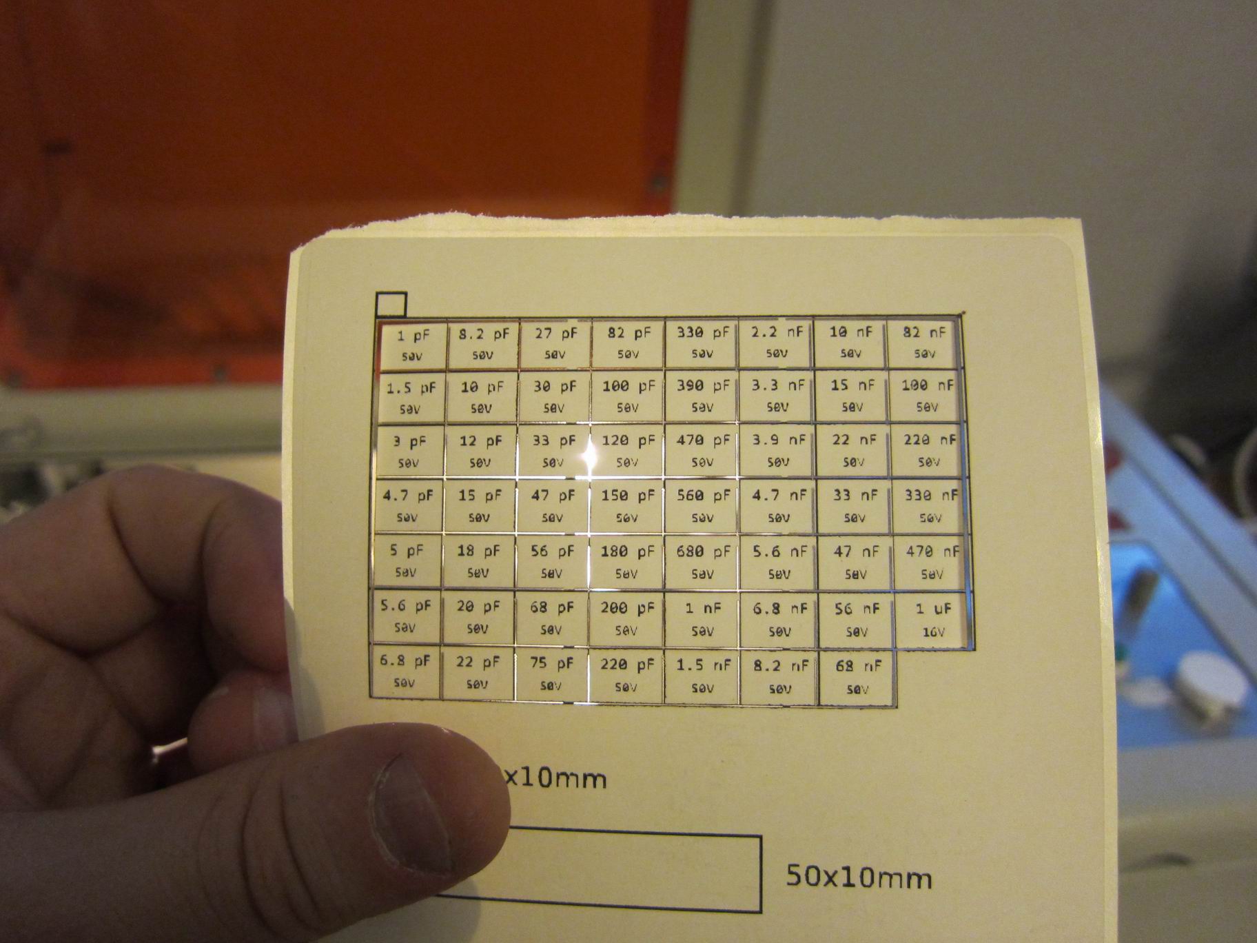
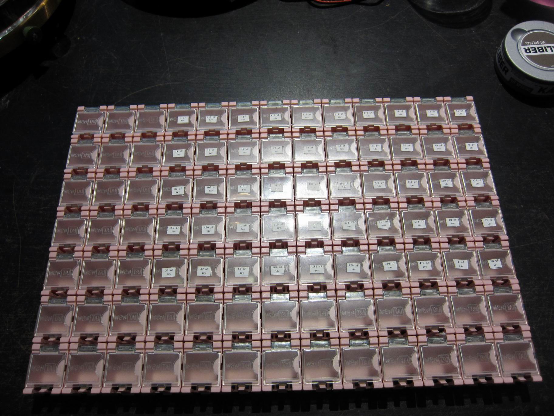
I’m too lazy to write every single label on my component boxes, so I used the laser cutter at my local hackerspace.