There’s a small festival up in Uddevalla (Sweden) called Elinorspelen. It’s a non-profit festival with the goal to have fun and spread culture. Unfortunately the festival have a very low budget and can’t afford all the equipment that it needs, and lighting has especially been down-prioritized.
Two friends of mine, and I, decided to do something about it. We got together and started discuss what kind of stage light that would be possible to buy/make.
We all agreed on that moving head spotlights would probably the cheapest alternative that gave the most visual effect.
Research
We started out to search for cheap LED-diodes to make our own spotlight.
But after a day or so we quickly found out that to just build the a LED-array would cost as much as a commercial spotlight. For example this LED PAR 56 black 151 LEDs RGB 16W for 296SEK.
We soon gave up the idea of making our own LED spotlights.
But we found out that all the cheap LED-spotlights had a very wide beam angle, and we wanted a very narrow beam.
Making an RGB spotlight on a tight budget
We got back to the idea of making an spotlight ourselves. Picking out narrow 10-13° viewing angle LED’s from Ledz.com.
As I started to pick parts to the project, the list grew longer and the price were raised by big numbers.
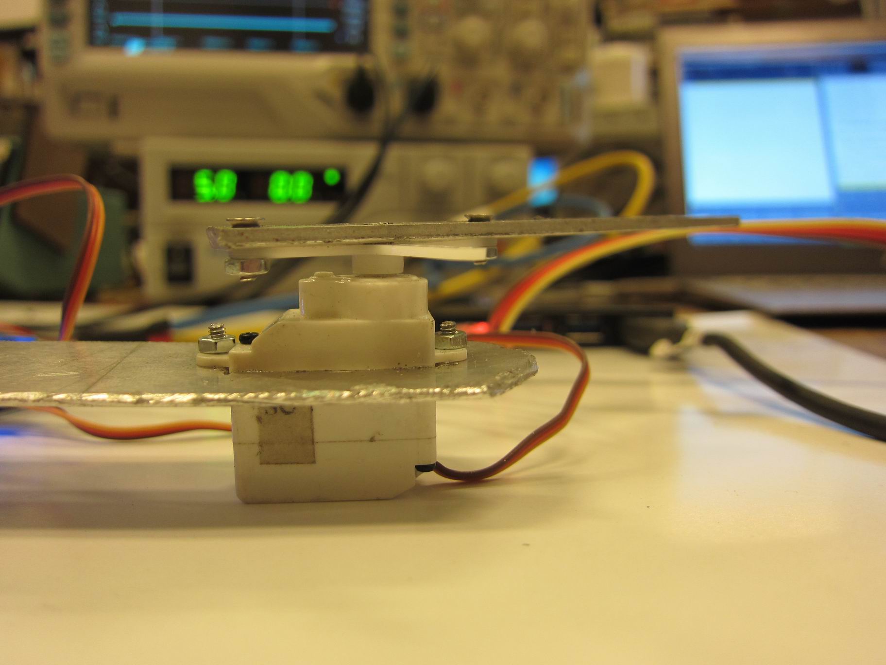
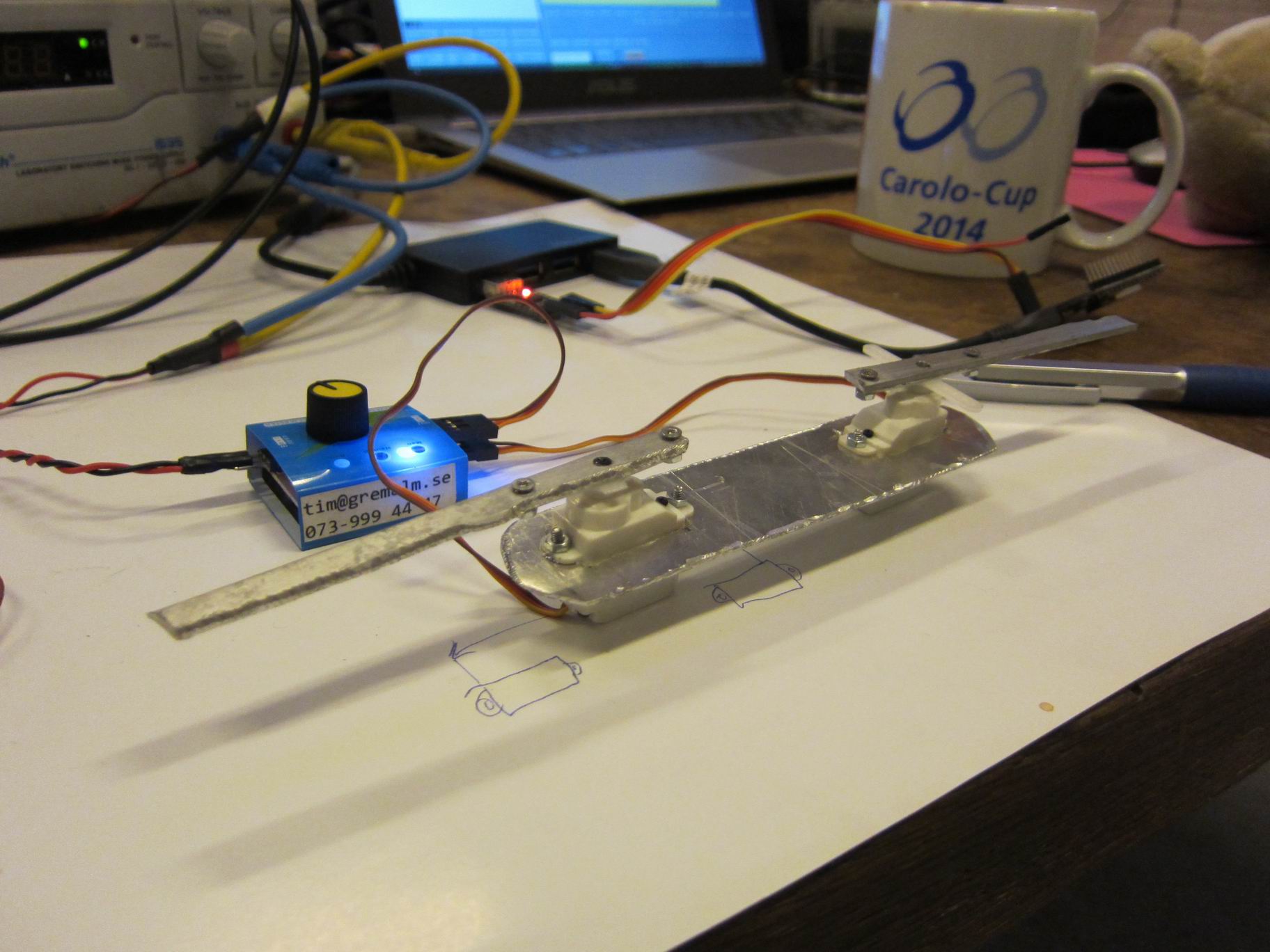
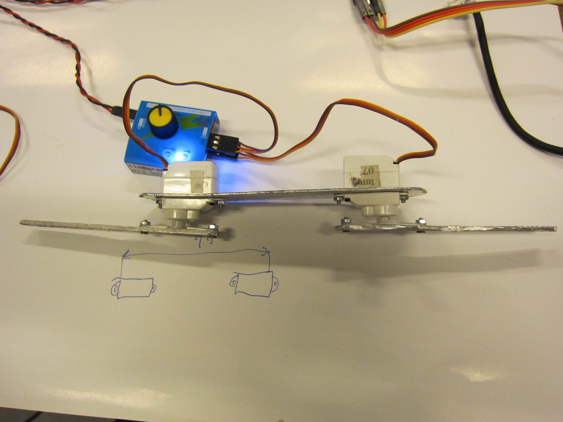
I managed to find really cheap geared stepper motors from eBay for a really cheap price; 28BYJ-48 DC 12V, plus controller, for around 26SEK a piece. After some research it looked like that model i widely used in different DIY- and Arduino-projects.
After a few weeks of picking components forward and back I’ve come closer to a final budget on 450SEK per spotlight, and that excluding some material prices like polycarbonate. I suspect that the final price per unit will end up on 500SEK. That’s at least 3 times cheaper than any commercial light.
You can find the budget for the spotlights here (Google Drive).
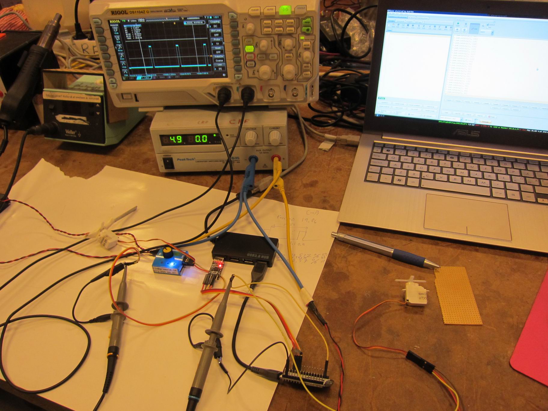
Electronics
I’ve just a basic idea of what components the electrical design needs. Some micro-controller based up on the STM32 series should work well.
Some mosfets to drive the LED’s.
The LED’s should be connected in series to 12V, and have the same pinout as the popular LED-strips that are so widely available now. This should make the testing very easy.
Designing the chassis and mechanics
The designing process were making its way alongside with the budget, a design-change could radically change the budget.
I had a pretty basic idea how I wanted the final product to look like.


A LED-array soldered on to a PCB, the PCB should be mounted directly on an axis that were attached in a U-shaped arm.
The PCB would make the LED-array really lightweight and it should not be a problem for the geared stepper motor to move it.
I also thought of having the cabling layed inside the axis, so why not make the axis into a tube instead of a solid rod?


Moving the U-arm
But how would the U-arm move? I knew that a central shaft would be the focus in this problem. It should be able to move a pretty heavy weight, PCB + Stepper motor + alot of polycarbonate.
I also think that the moving head spotlight should be able to be mounted in several ways; placed on a flat surface shouldn’t be a problem. But be able to hang upside in a ceiling, or hanging from the side of a wall, that’s tough.
The center-axis mus be able to take on forces from many directions.
One thing was for sure, we needed alot of bearings.
With the bearings a shape took form, centered around the axis.
4 bearings are used on the center axis. 2 axial bearings to make it spin easy upside down and standing. And 2 bearings up and down to make the center-axis stiff and prevent it from leaning.


And around the bearings, the framework took place.


Somewhere here the pieces started to place them selves in the big puzzle, it was much easier to design now.
Around the framework we needed a casing to hold out dirt and to keep it pretty.
It’s hard to make a nice chassis by yourself, so I started to look around for a cheap case designed for another purpose.
I found this cheap water bawl for dogs for around 17SEK. It’s about 200mm in diameter and should house the mechanics and the framework nicely.
Designing in CAD
It’s one thing to have you design in your head and on paper, but it’s hard to grasp if it will fit or not. It’s here CAD-design comes into the picture.
I started to draw the different parts needed. As I draw the parts I could easily adjust lengths of parts to fit each other. Make puzzle-slots for the different pieces in the U-arm.
I try to make an easy design that could easily be milled out in our CNC-machine. The most parts are made so they could be cut out in X-Y-axis. I’m also trying to make as long and narrow pieces as possible, because long pieces are easier to fit narrowly on to a big polycarbonate-sheet.
The last part of the CAD-design was to put it all together, attach bearings to the shaft, build the U-arm.


The first design is now complete. We’ll have to make several adjustments to the design in iterative steps.
But for now, I’m thinking it’s starting to look good!