Folkrace 187


In Swedish Robot Championship there’s a tournament that is called Folkrace where autonomous cars is racing around a track. A sub class of this is a miniature race in scale 1:87.


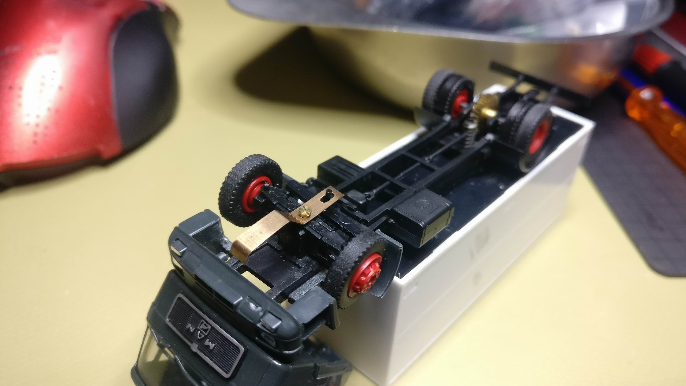
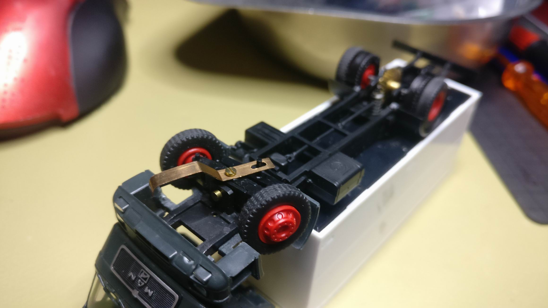
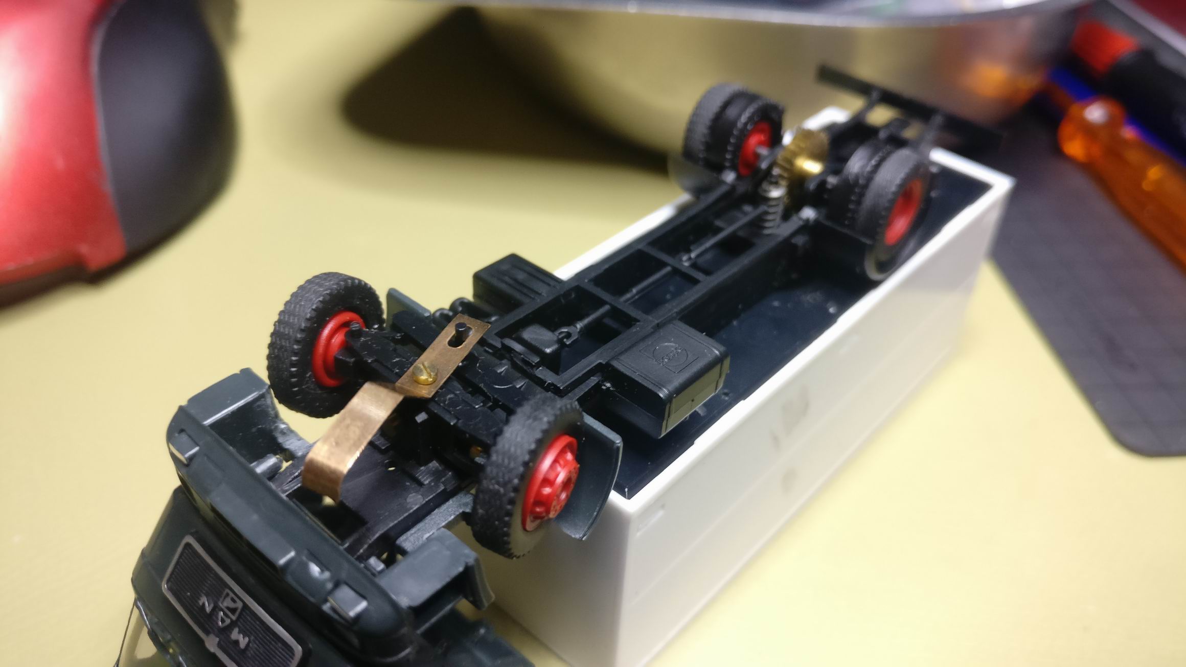
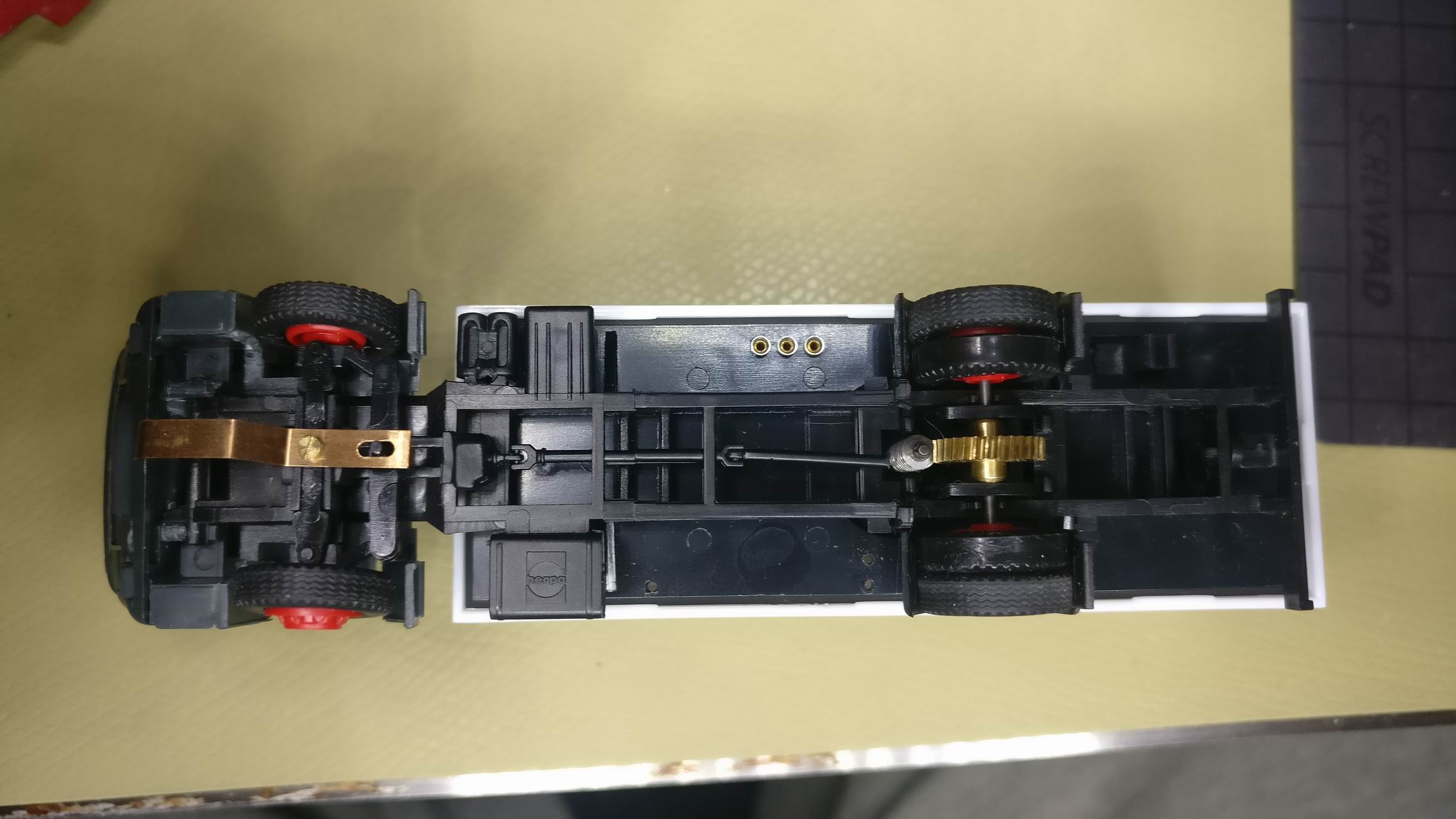
So I started out on a Fuller Car system truck in scale 1:87. It have some really nice suspension and drivetrain but is made for following a iron track.


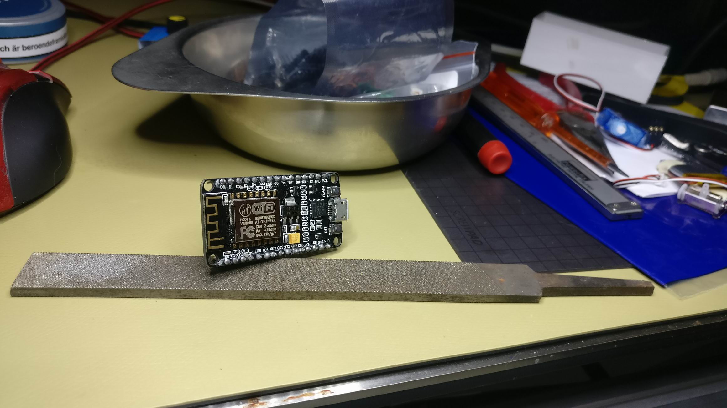
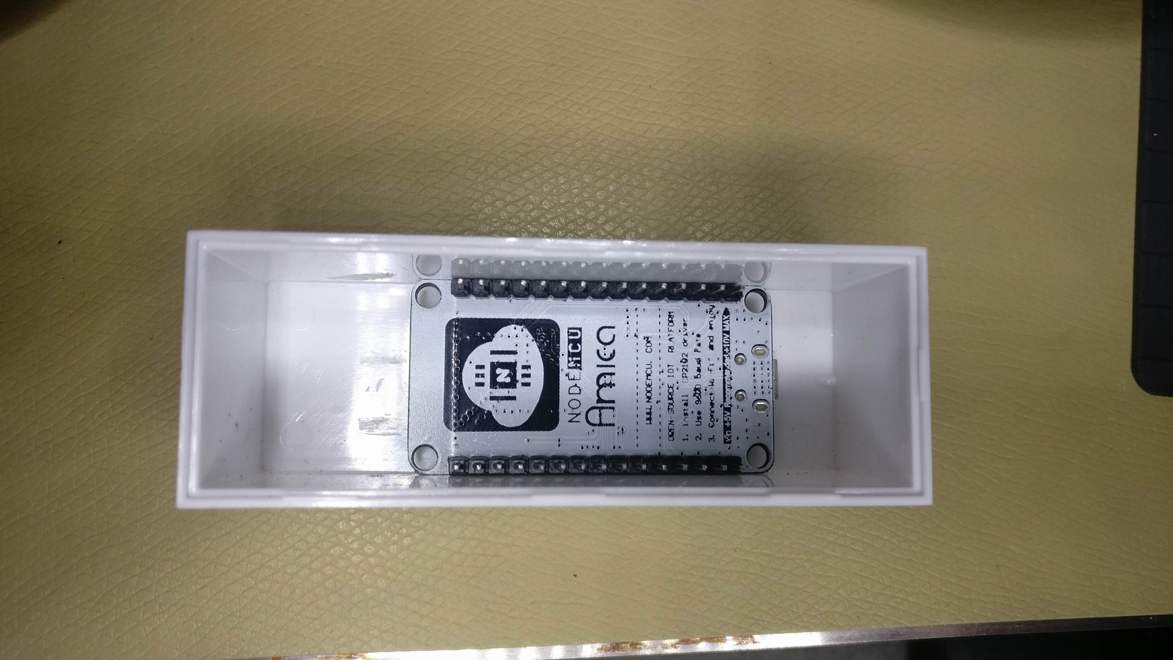
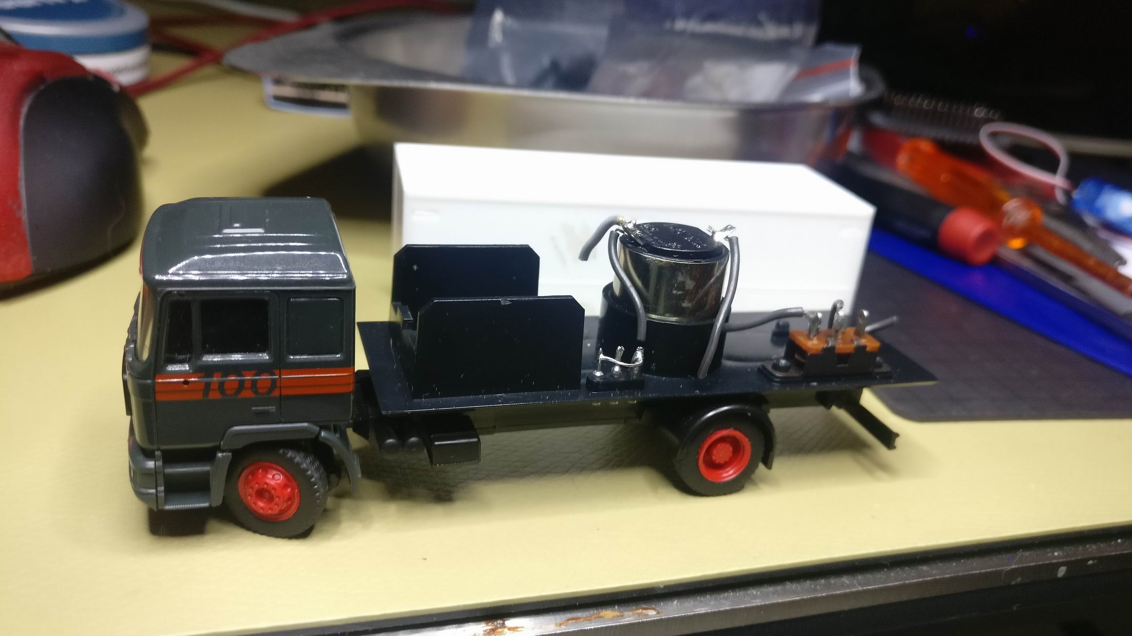
A NodeMCU development kit (ESP8266) almost fitted the truck bed, if i filed of 0.5mm of it i fitted perfectly.


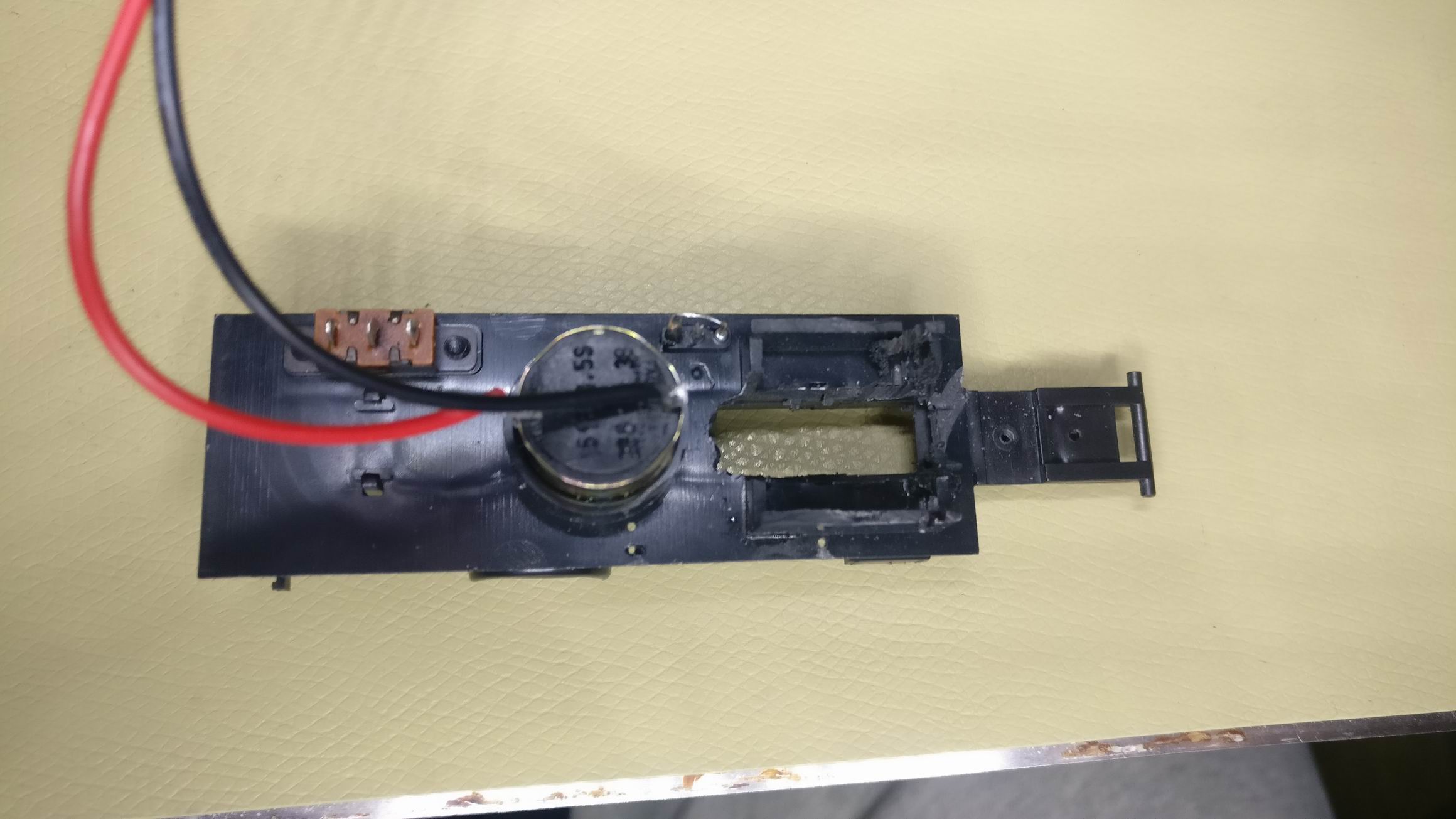
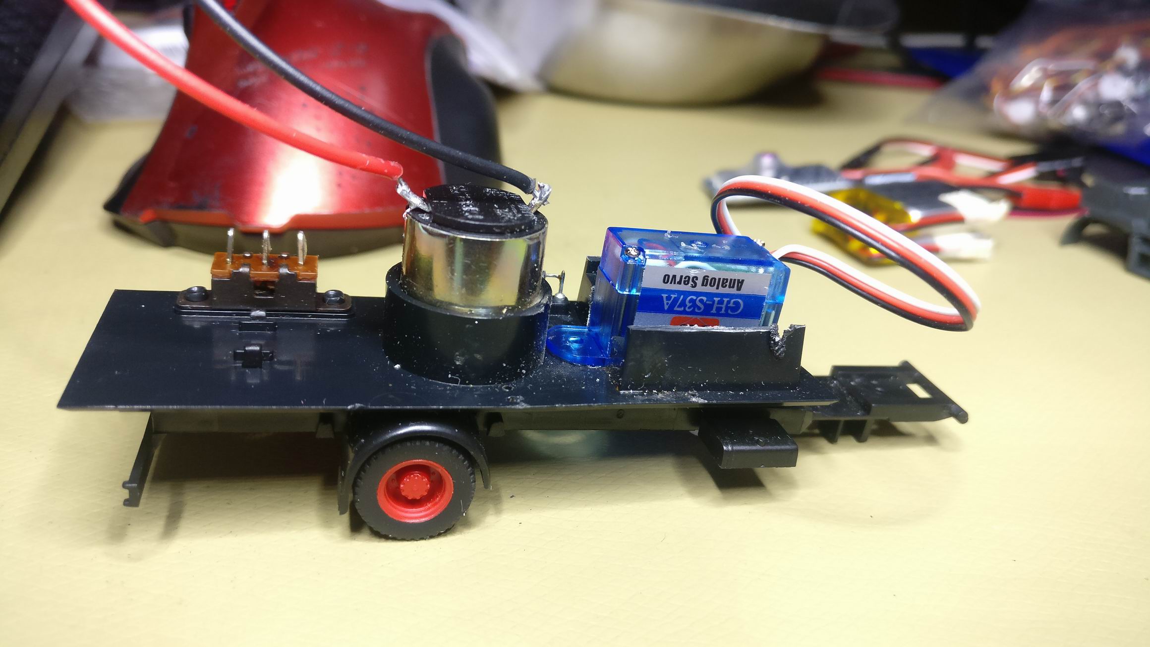
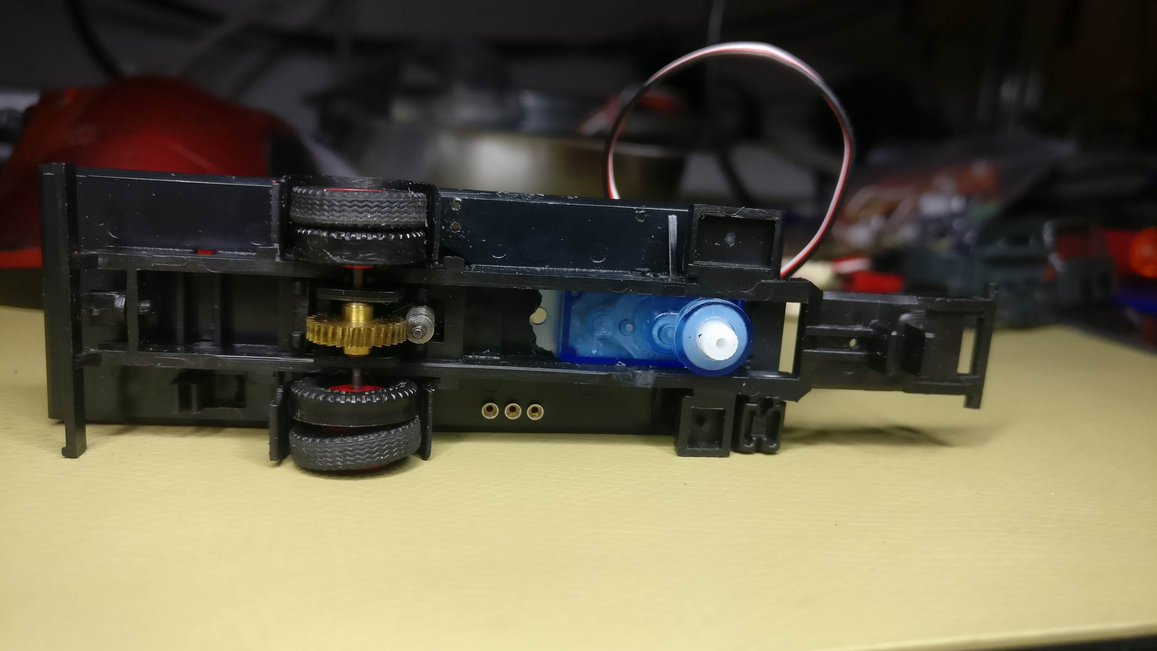
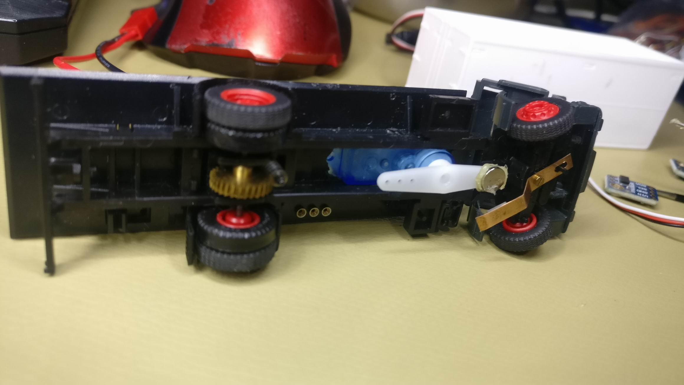
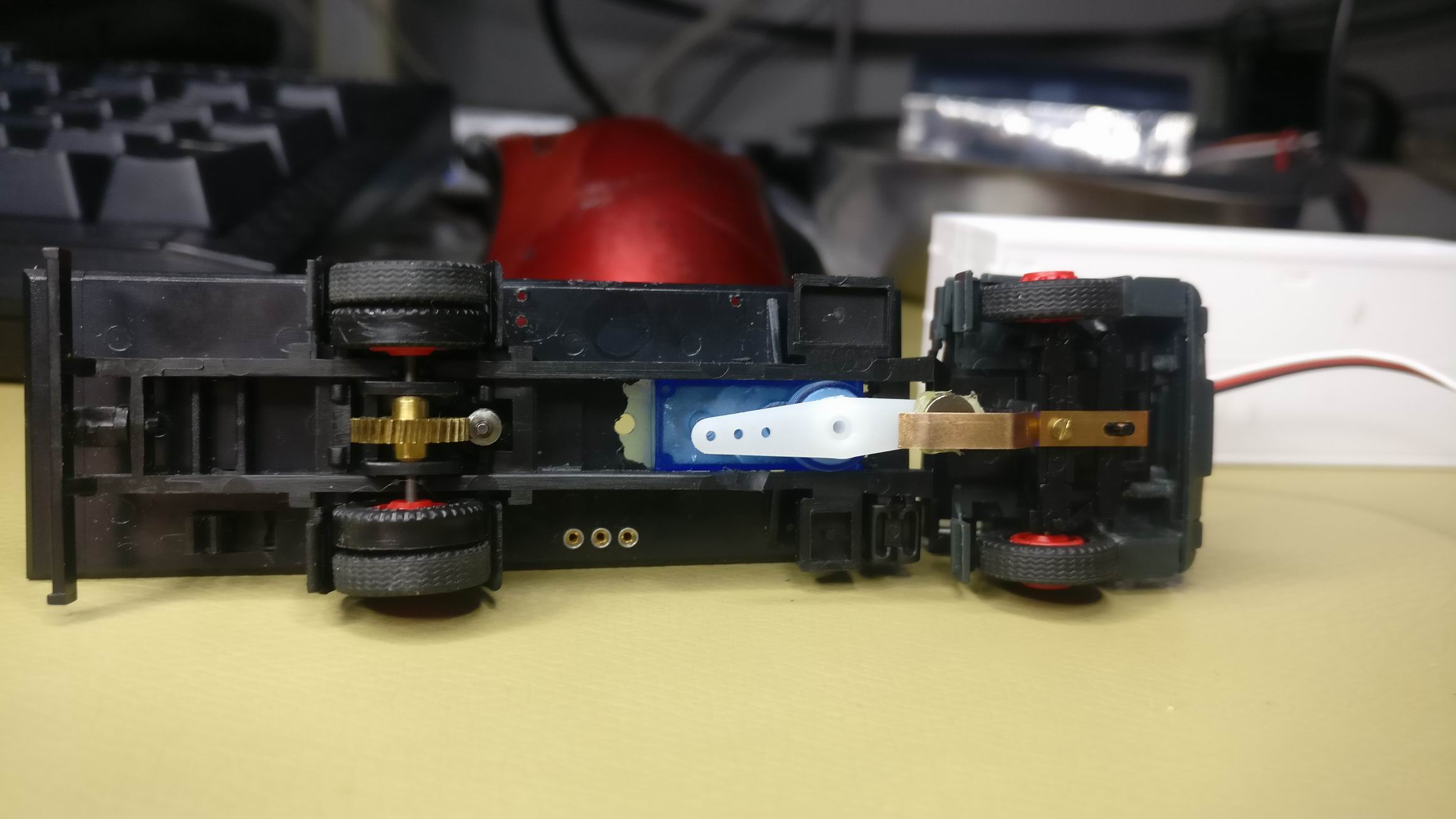
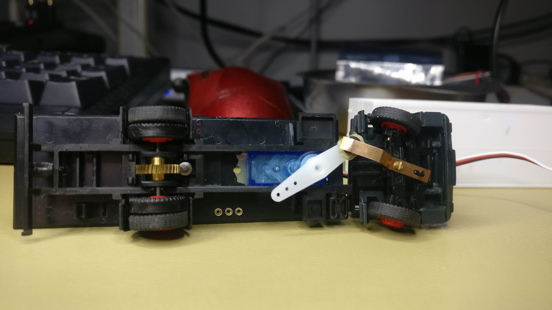
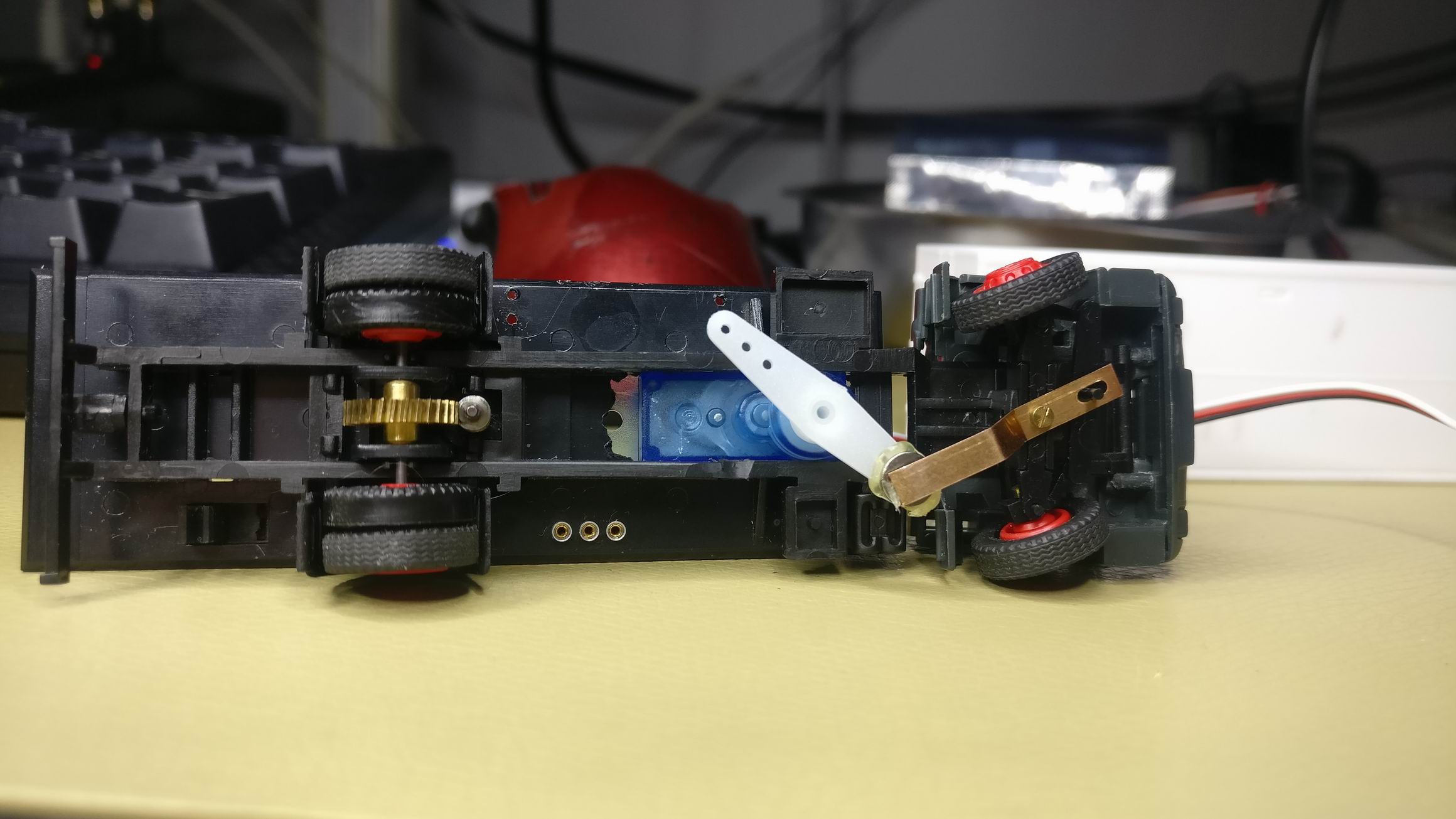
I solved the steering by cutting a hole, big enough for a small servo, in the trucks chassis.
Then i glued on a small magnet that aligned with the already existing magnet in the steering system.


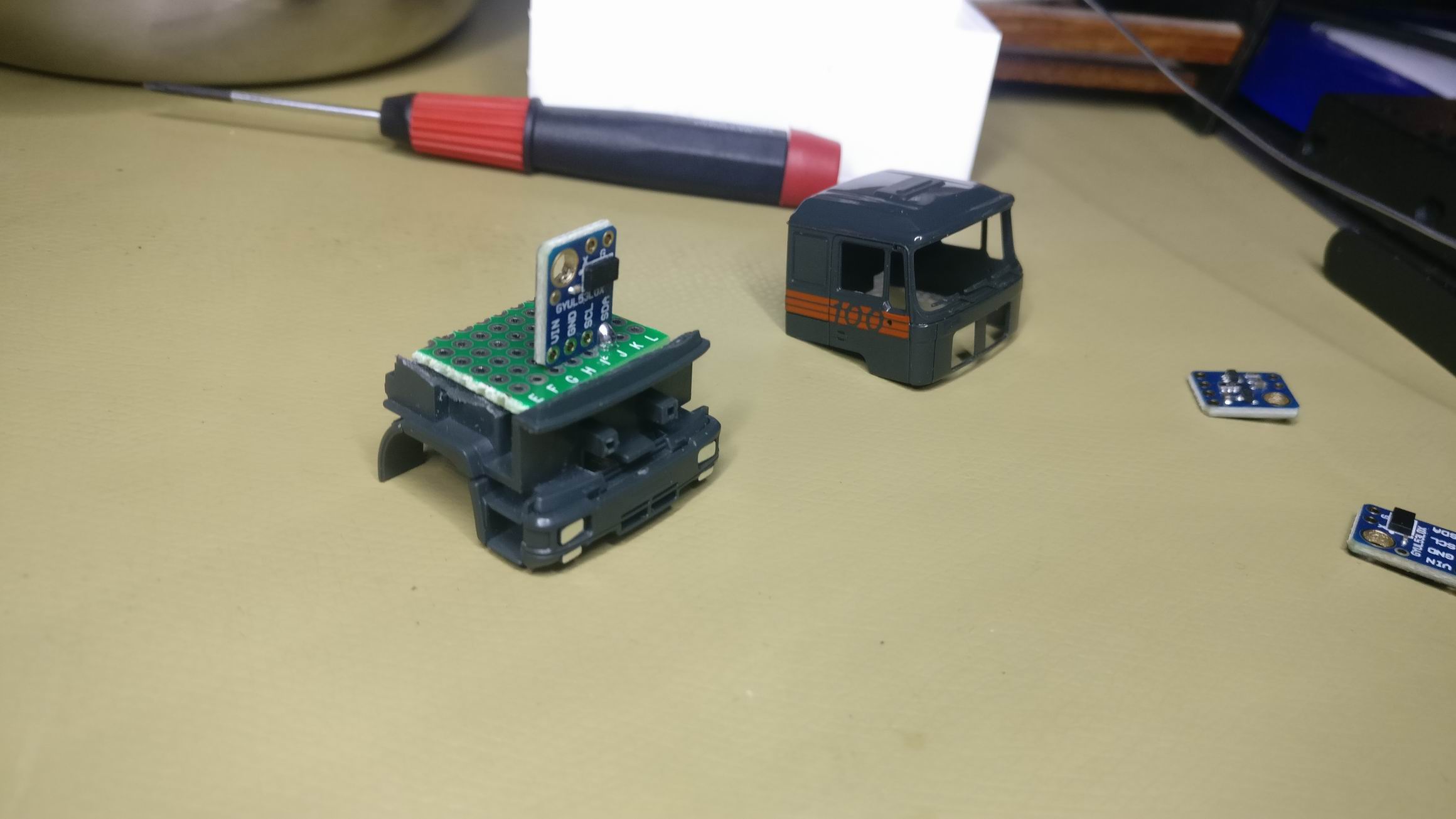
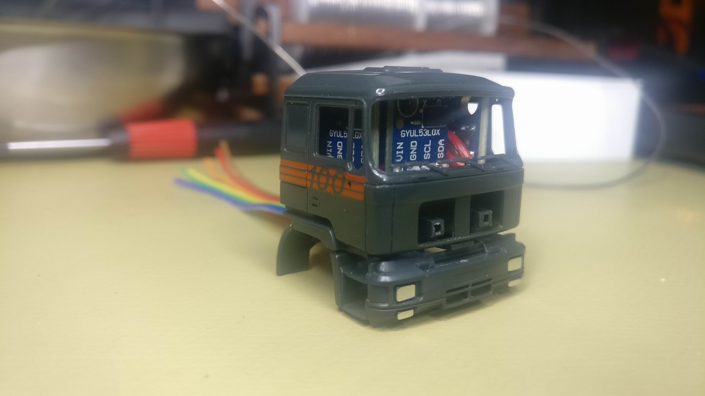
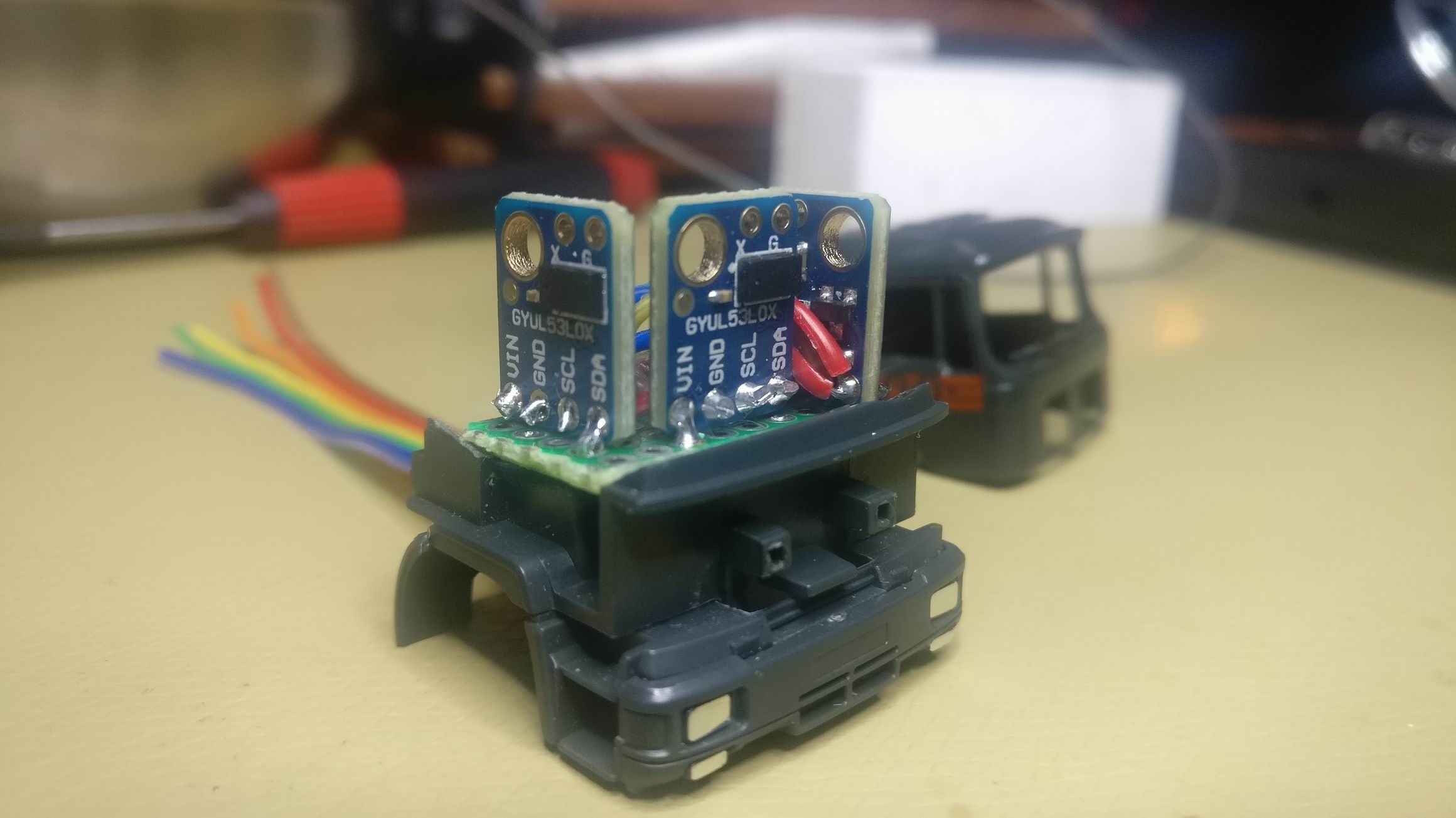
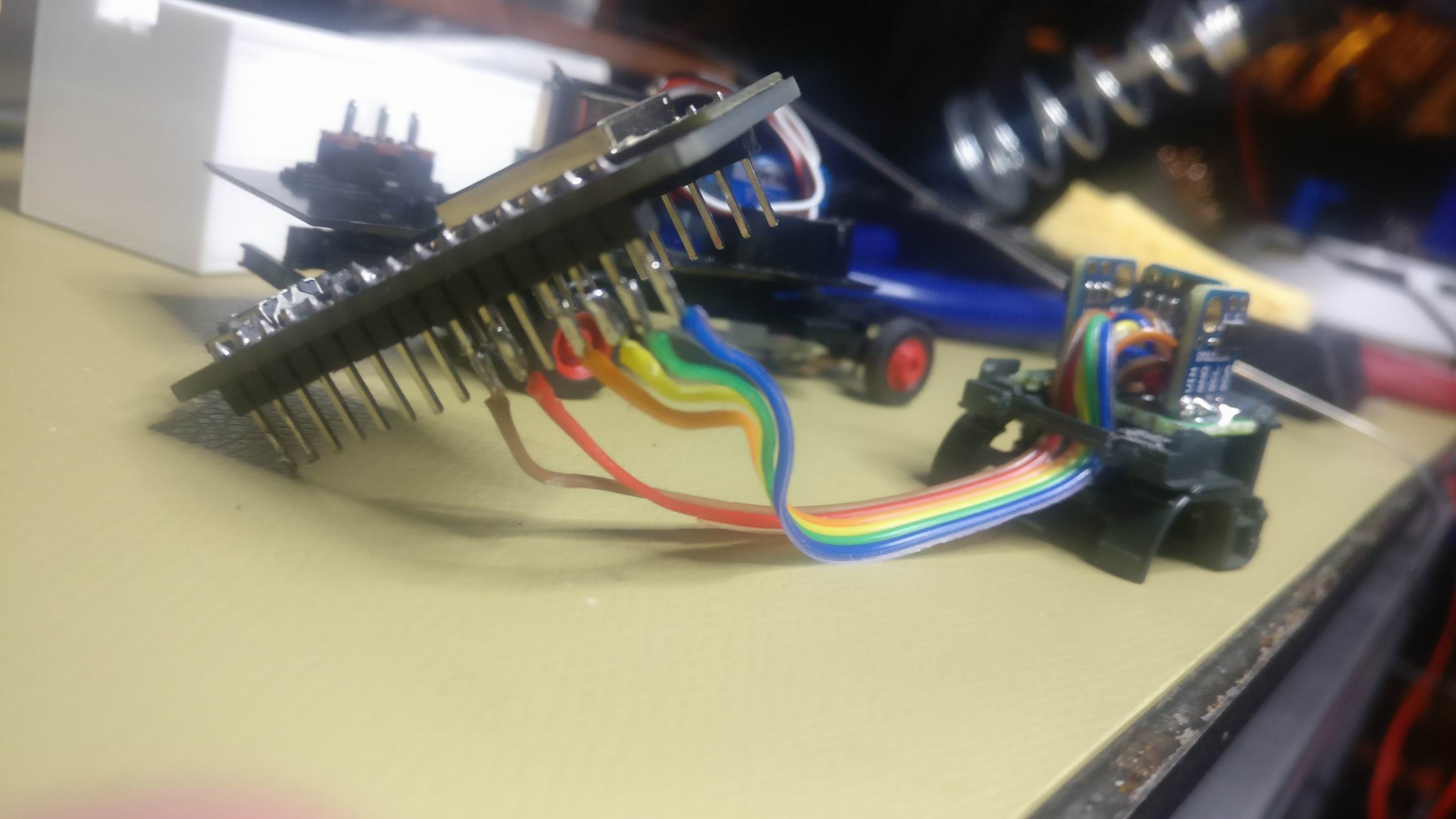
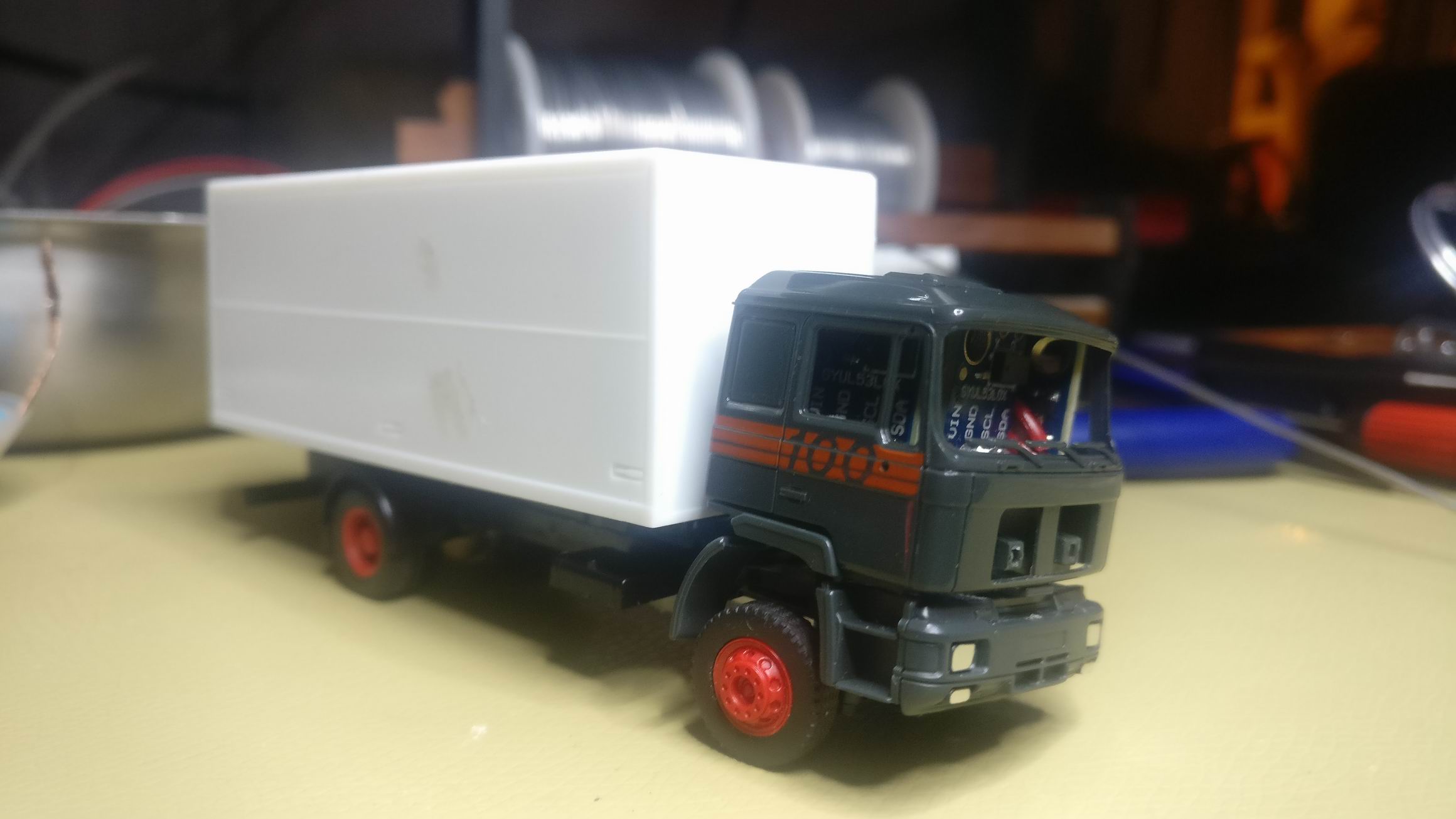
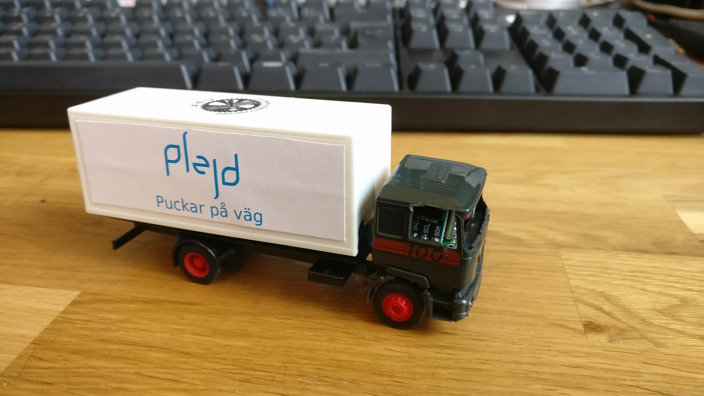
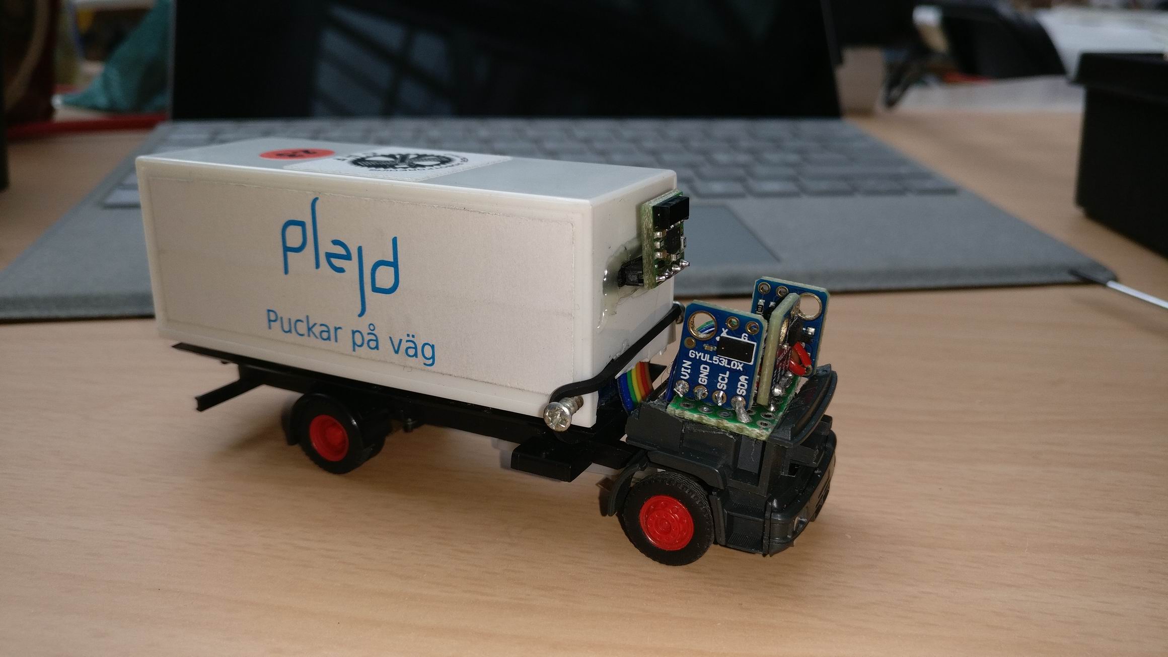
I then mounted 3 VL53L0X ToF (Time of FLight) distance sensors inside the cab of the truck. The sensors is pointing out from the same holes the windows are located.
The sensors will be used to locate walls and other trucks, it’s gives a pretty low resolution, but should be enough.


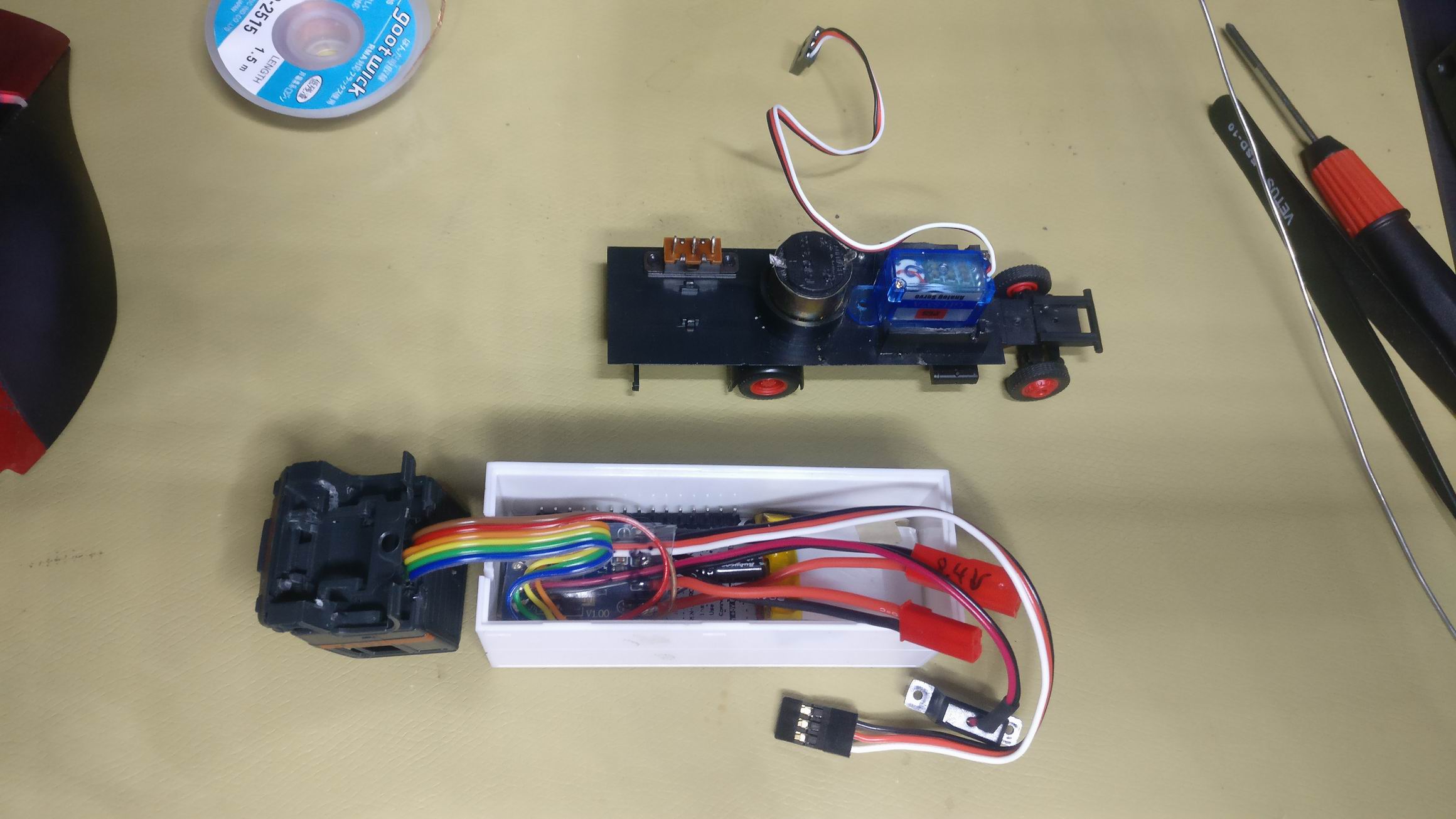
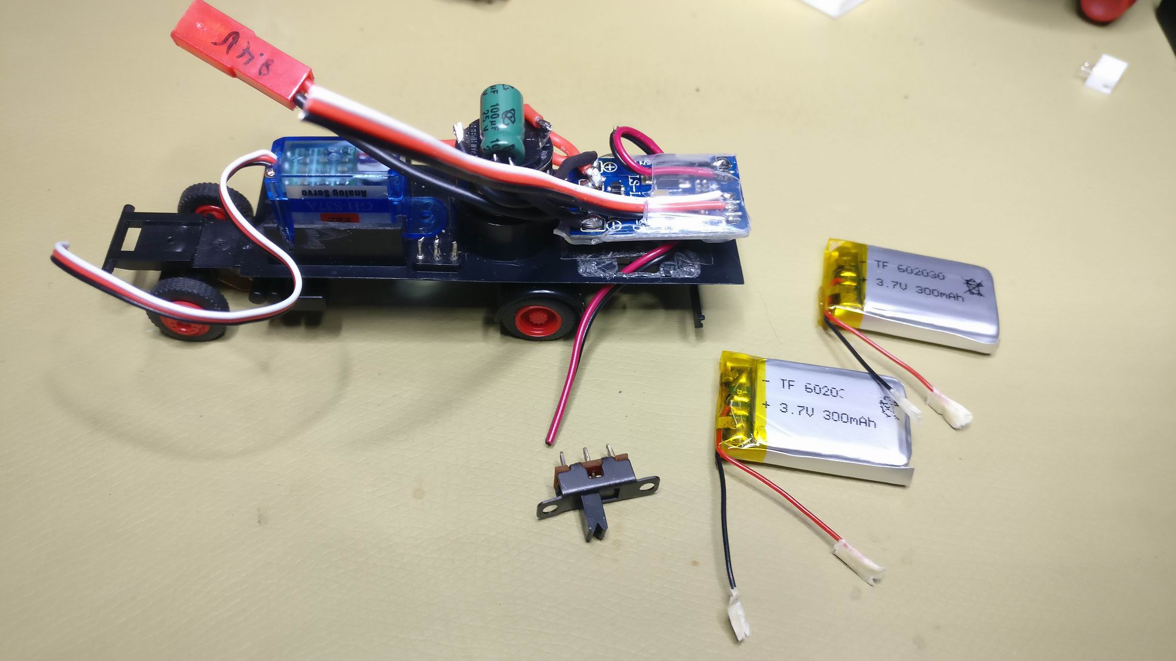
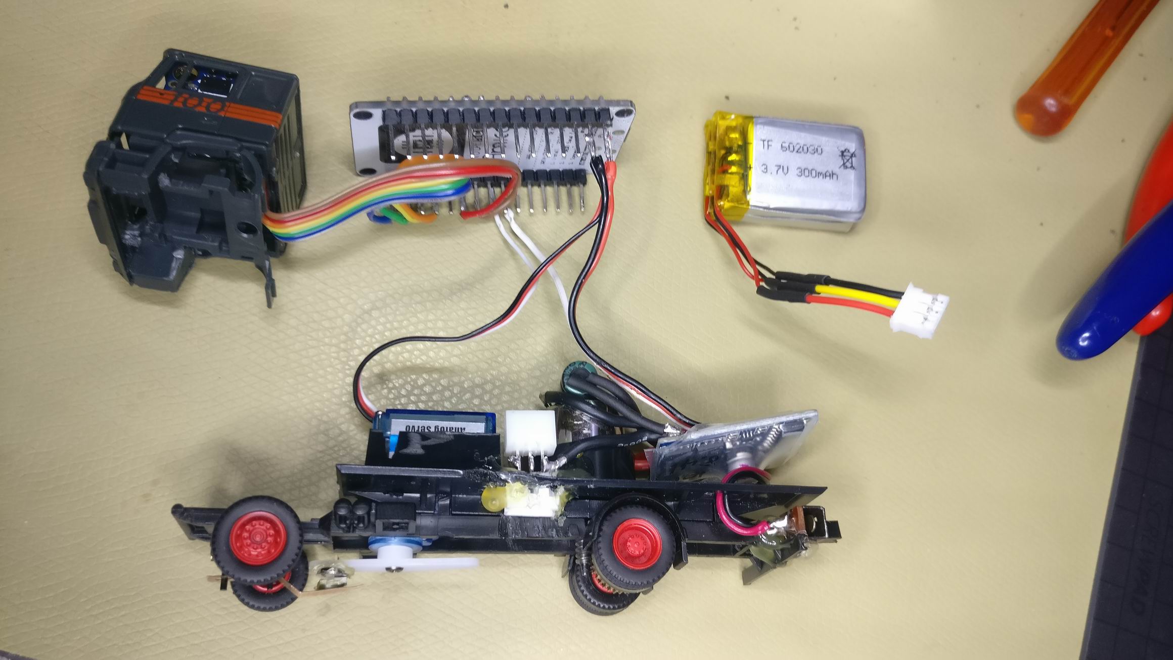
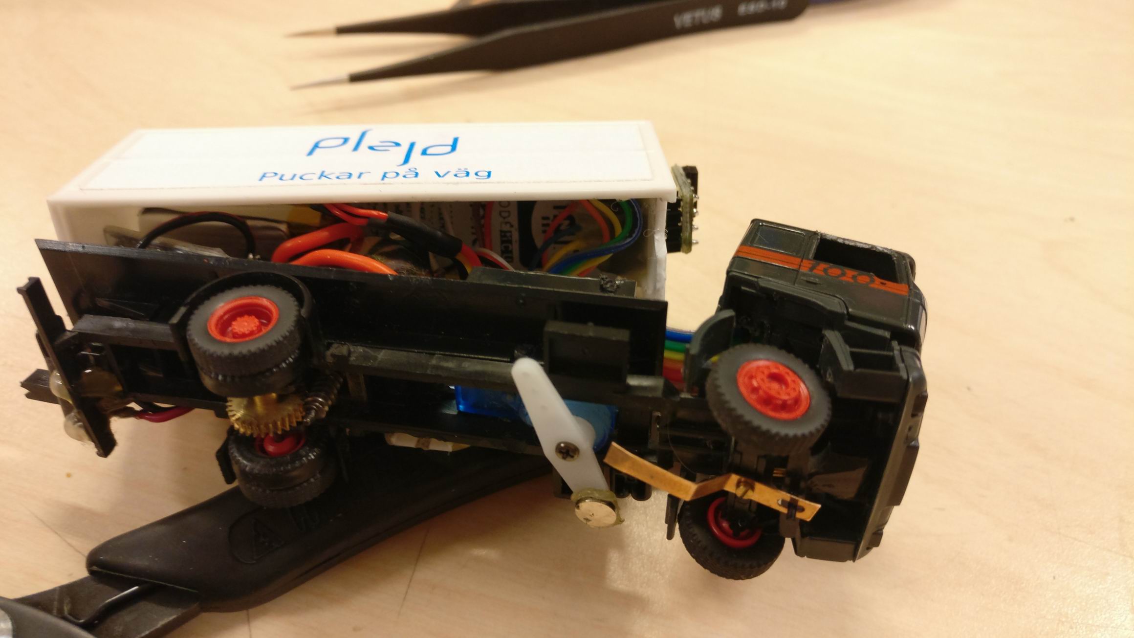
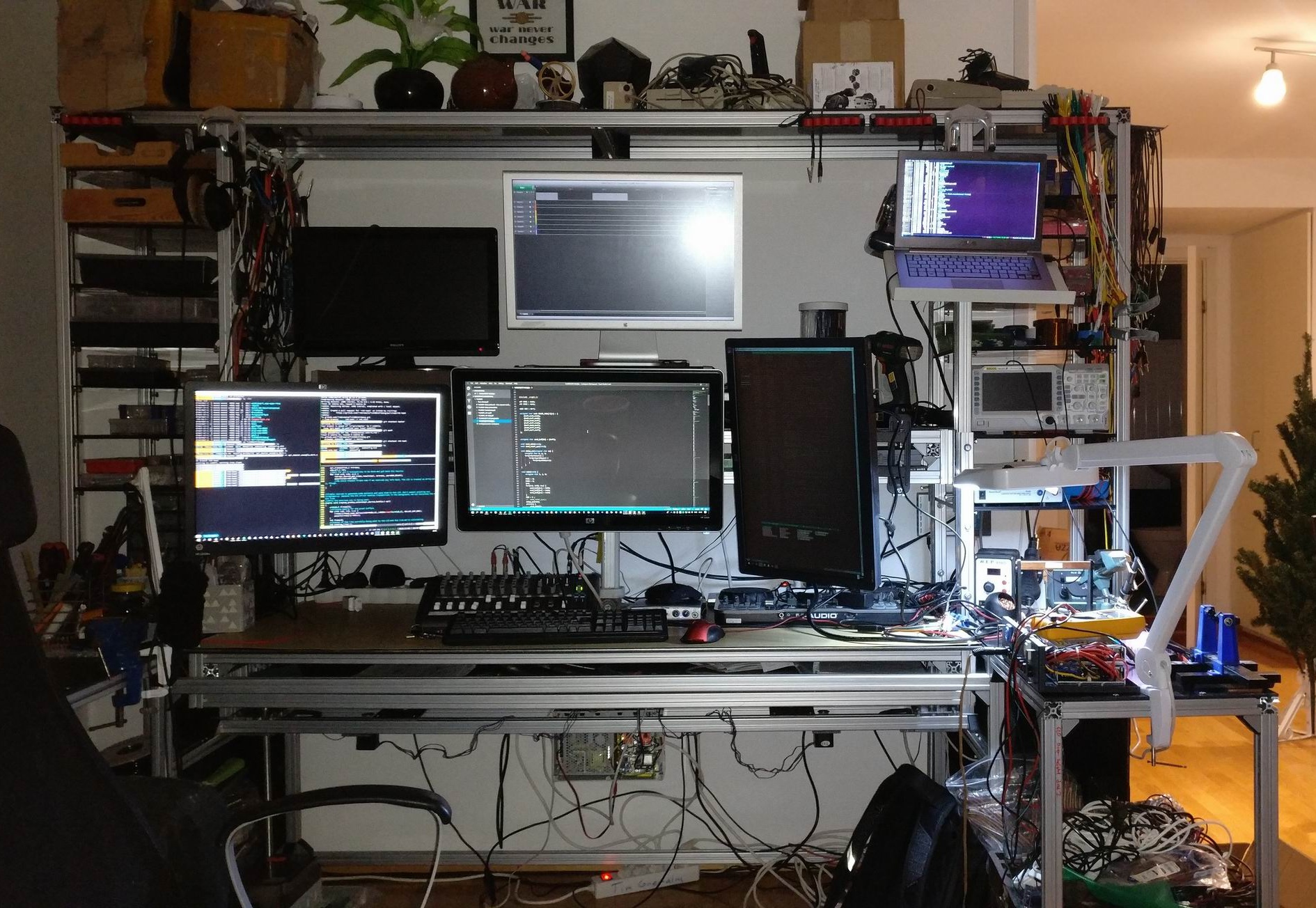
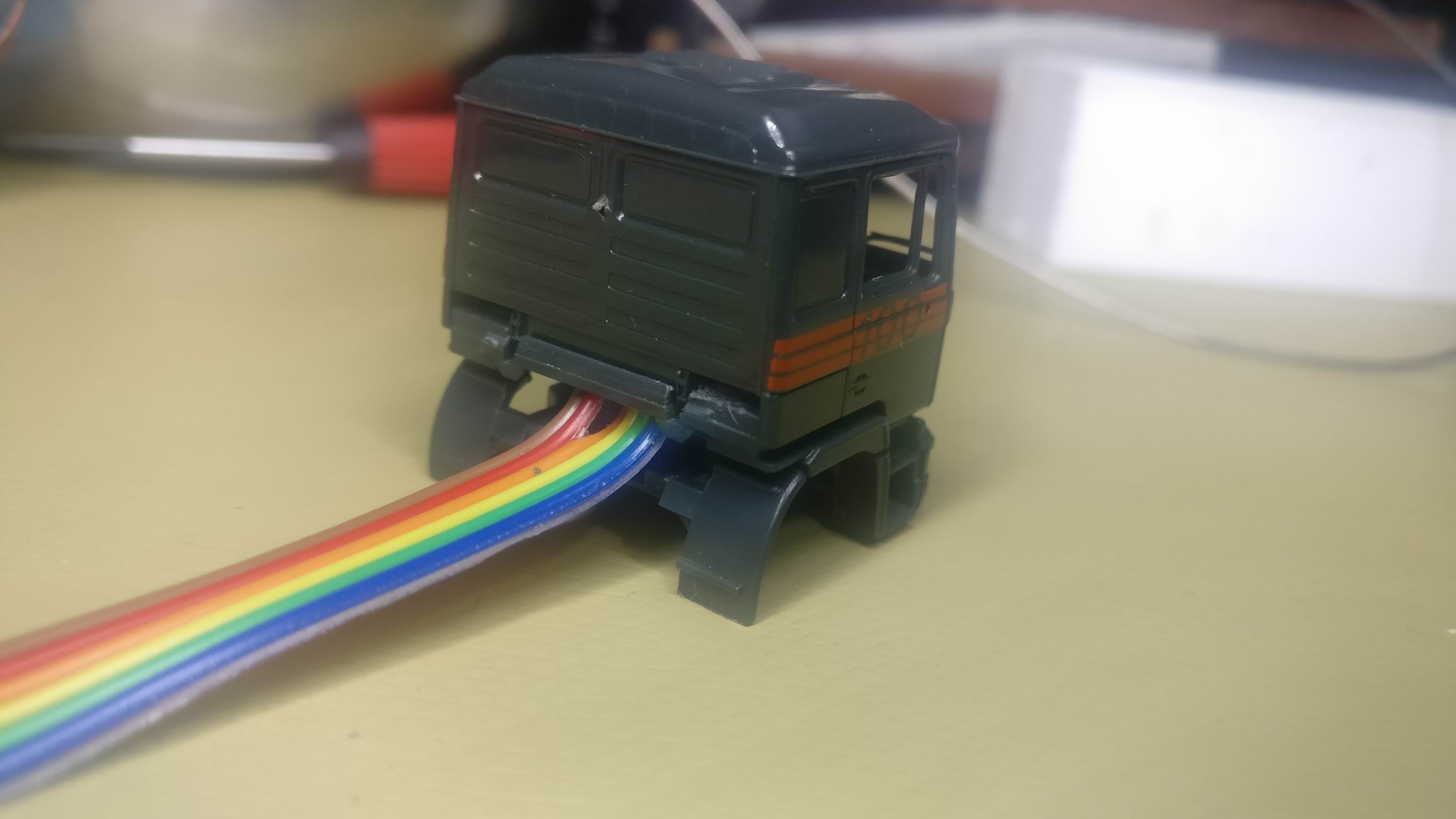
The space inside the truck bed is cramped, and I mean it. After fitting a small H-bridge, a couple of batteries and some cables together with a start module nothing more can fit.

As if the cramped space inside the truck bed was not a challenge big enough I choose to run Micro Python on the MCU.
It’s pretty nice and all, I could remotly upload new Python code to the flash and run my test scripts inside a Python interactive terminal.
You can find the code here: https://github.com/TimGremalm/Folkrace187

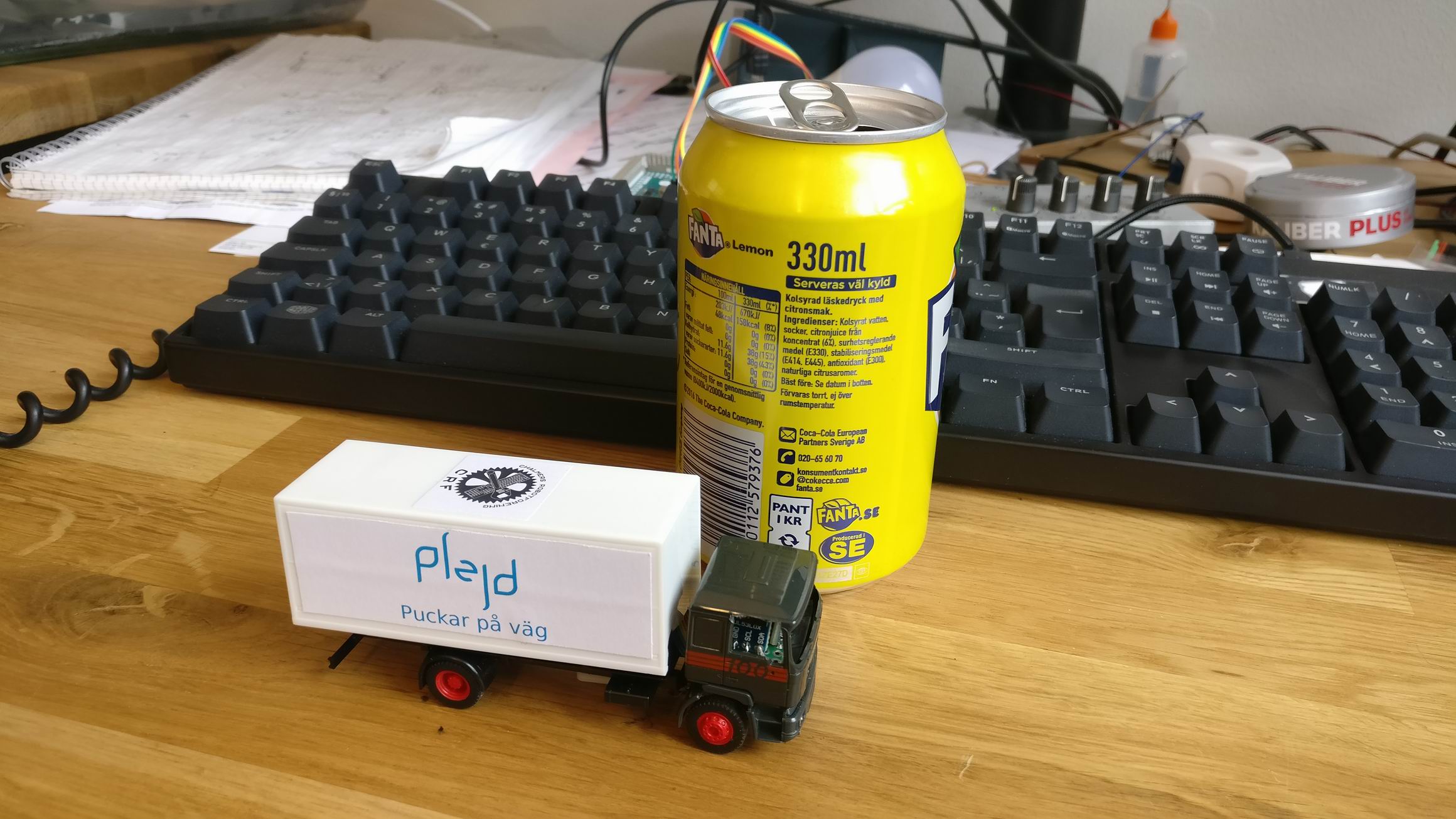
I found the challenges of the small form factor thrilling, it was a really fun adventure puzzling everything together and make it look pretty stock.
But there is room for many improvements! The Fuller Car system have a very nice steering system, and it’s very useful for a future design.
But Fullers drive train is a worm gear, it makes it strong but gives the drive train some momentum that makes the car slow in response when braking och switching between going forward and backwards. For future builds I would have to build my own drive train.

The cramped space inside the truck bed is due to a lot of premade modules and a lot of cables. A more effective way of doing it would be to make a PCB with a ESP8266, H-bridge and sensor bus built in.

Also I think I would abandon Micro Python for C and Free RTOS. The VL53L0X driver is very slow in Micro Python and it takes too long to read 3 sensors. The whole driver thing is pretty hard to fault find and gives great me a great hazzle.

Skrivbord – An overengineered workstation


So I have wanted to build a desk for many years now, ideas have grown and so has the big feature list. But since my interest have moved away from software to electronics my requirements have changed. I need a lot bigger work space for tools and more shelves for instruments, and still a lot of screens.
So 3 years ago I started on my desk design. I decided that I wanted to go for aluminium profiles for my frame, both because it’s flexible and something I had not tried it before.
I also wanted as much of the construction to be as precise as possible, so everything is constructed in CAD. Mechanics strength tested, mechatronics is movement tested, material purchase planned and material is CNC cut as much as possible.
By the end of 2018 I started the weeks long process of assemble it all.

I made a drawing with assembly instructions based on my CAD design Skrivbord (Workstation, Gremalm).pdf. But I quickly decided to change the assembly order to make two stable outer pieces to build the rest on, it also meant that I didn’t have to turn the whole assembly too much.


The two outer pieces assembled.


Sliders for the raise-able desk and shelf are mounted on the sides. It’s MGN12H linear sliders often used in smaller CNC builds.


Desk assembled.


Center pieces to hold the two sides together.


To make the desk move up and down in the sliders I’ve constructed a linear actuator using a threaded rod, some pulleys and a stepper motor. It all goes together in this lower center assembly.


The desk was lifted in place and screwed into the MGN12H blocks. It should have been a lot of over constrains in the desk assembly, but it could move up and down pretty easy.


The desk shelf will hold all the monitors, and is attached to the big desk. That means when the desk is raised or lowered the computer monitors will follow. I used an old used actuator for this purpose that I had laying around.


Instead of using CNC cut polycarbonate I ordered laser cut ABS sheets for the desk because it was a lot cheaper. I found this neat laser cut order system where I could upload my DXF-files directly on the web and isntantly get a quote. https://smidyo.com/


To raise and lower the desk I made a small control box. It have two stepper drivers inside that drives each side of the desk.
A VL53L0X ToF (Time-of-Flight) sensor is measuring the distance to the desk so the control box can regulate the height. This also gives me an absolute height of the desk when restarting the MCU.
An ESP32 connects to a MQTT server and serves a desired height topic, when a new goal is set the control box will start to raise/lower the desk until the goal is set.
https://github.com/TimGremalm/SkrivbordDeskStepper
There’s also manual override for the desk with ordinary switches.

So in the end, was it worth it? No; the whole construction ended up far too expensive both in cost and time. But it was a nice experience to design something this big and follow through building it.
A far more effective workstation would be to purchase a cheap Ikea shelf and then place a raisable desk in front of it.