Interactive LED balancing board

A video posted by Tim Gremalm (@timgremalm) on


IMG_6636
IMG_6637
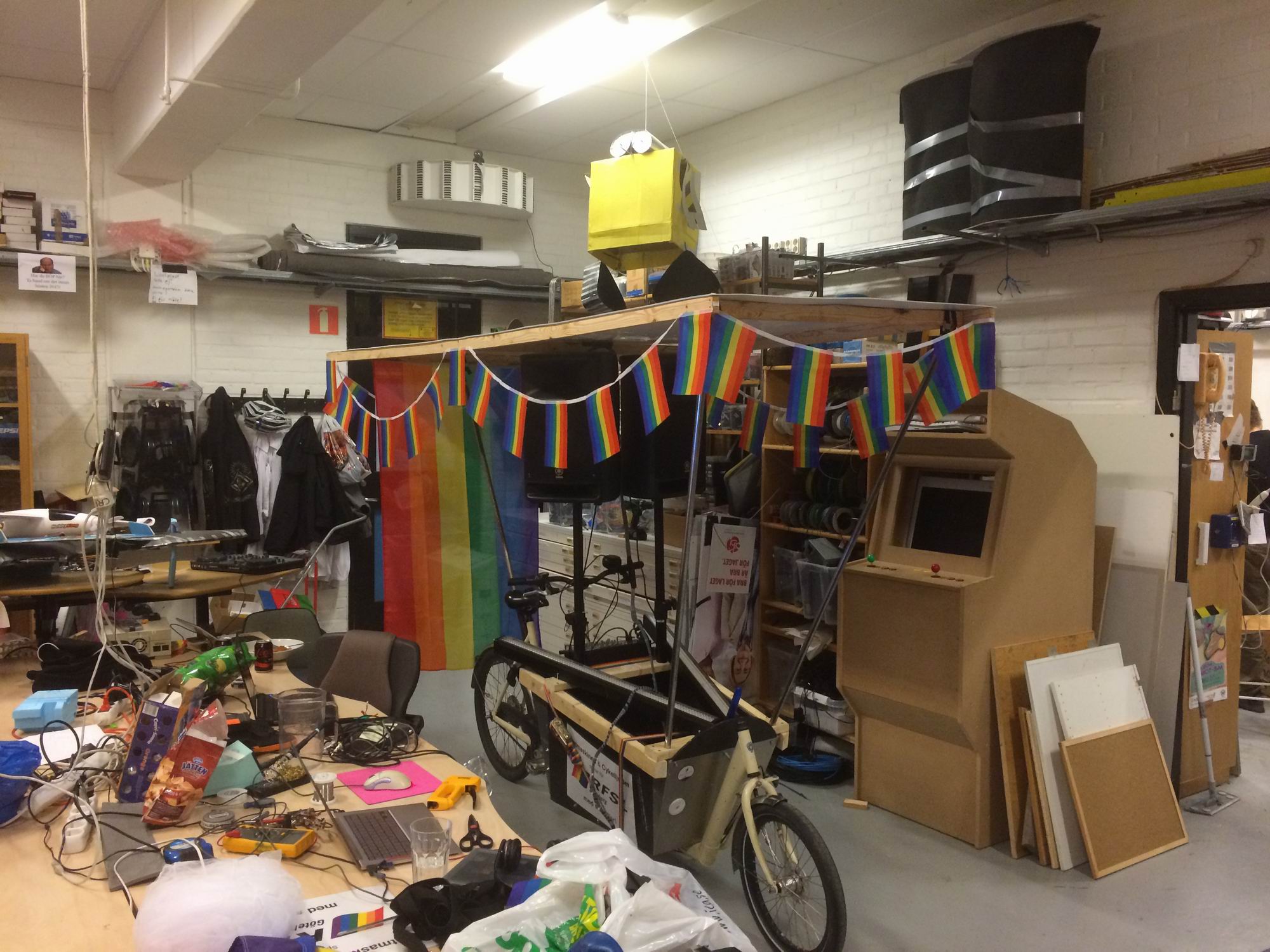
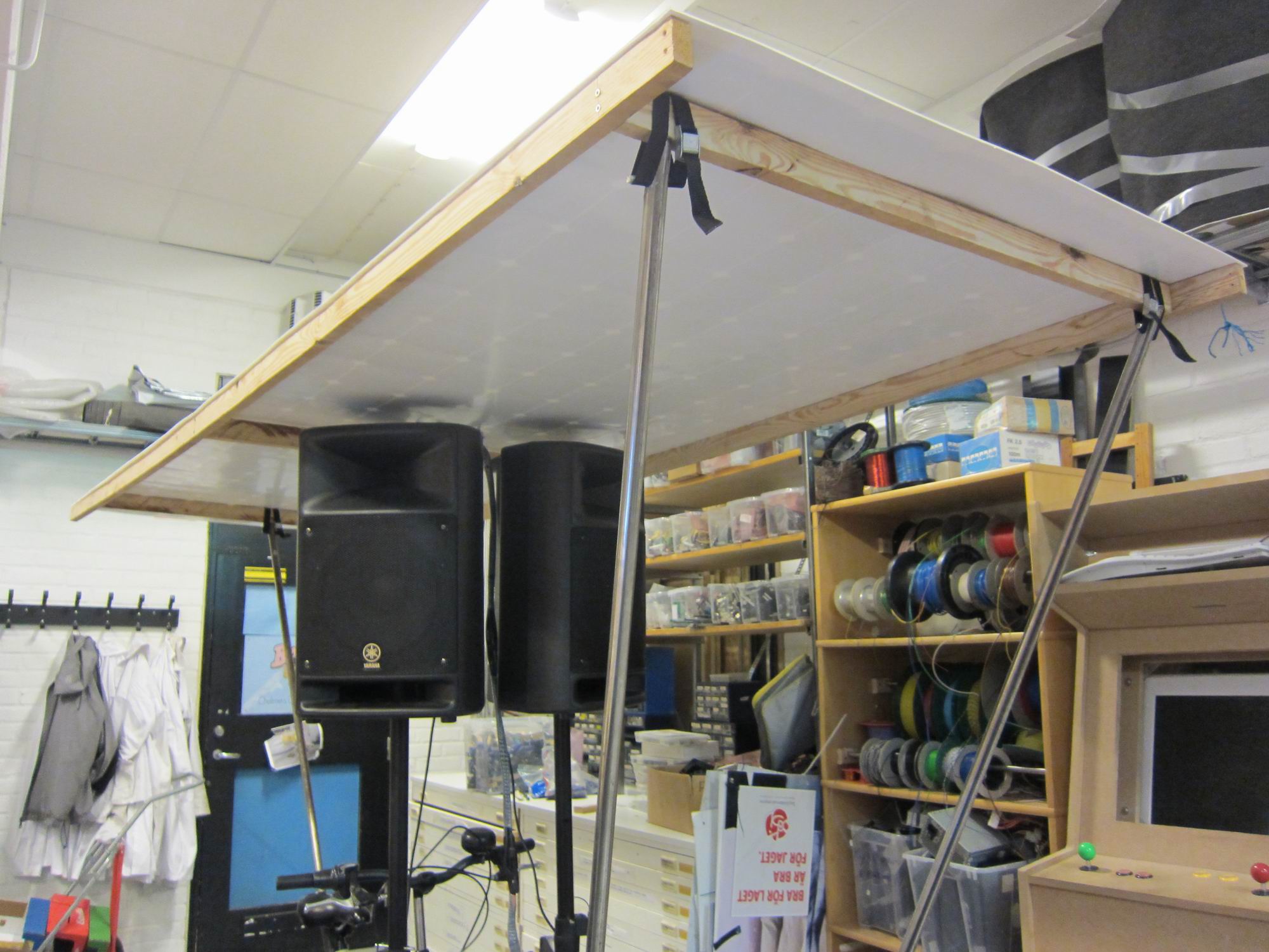
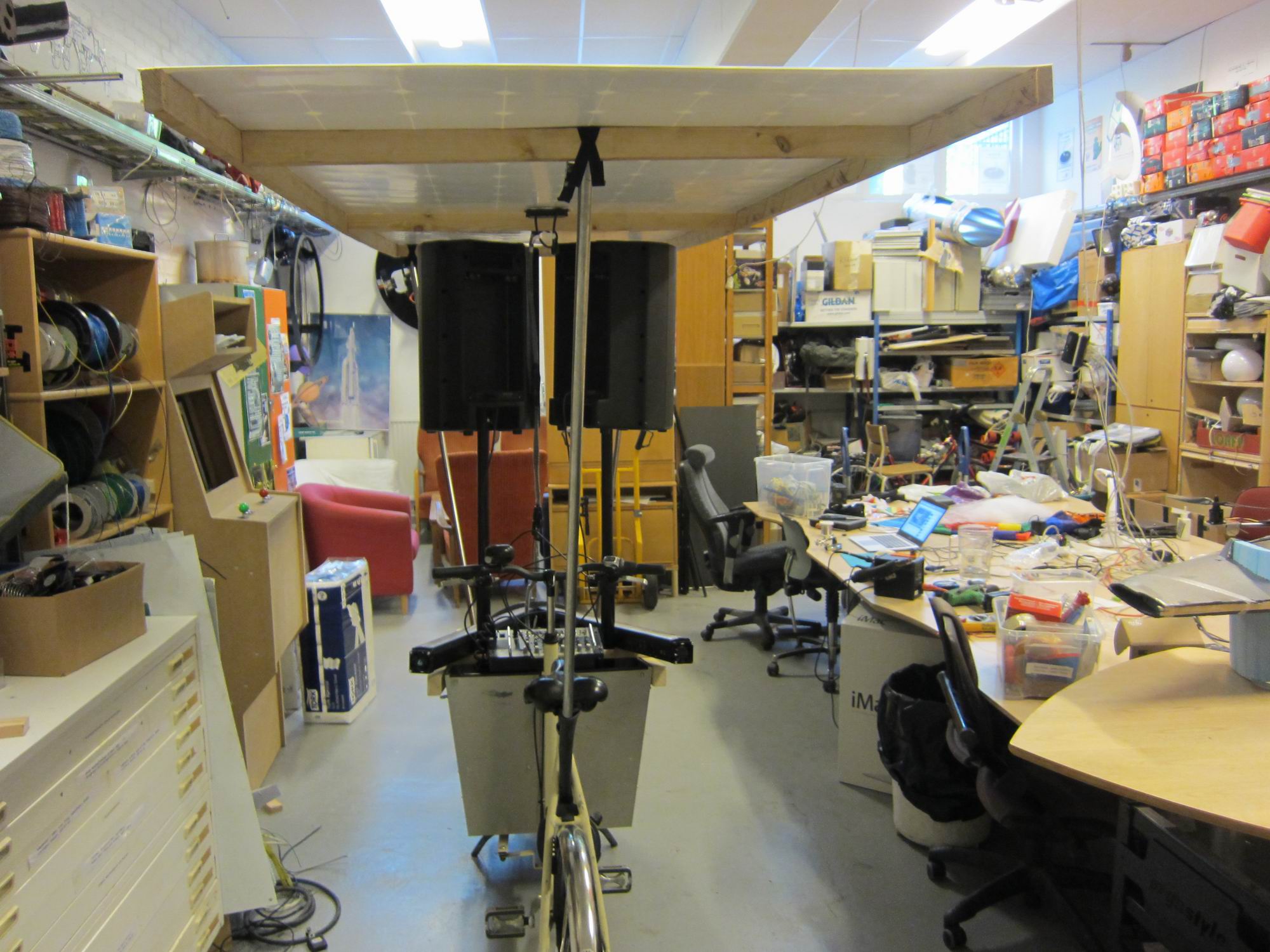
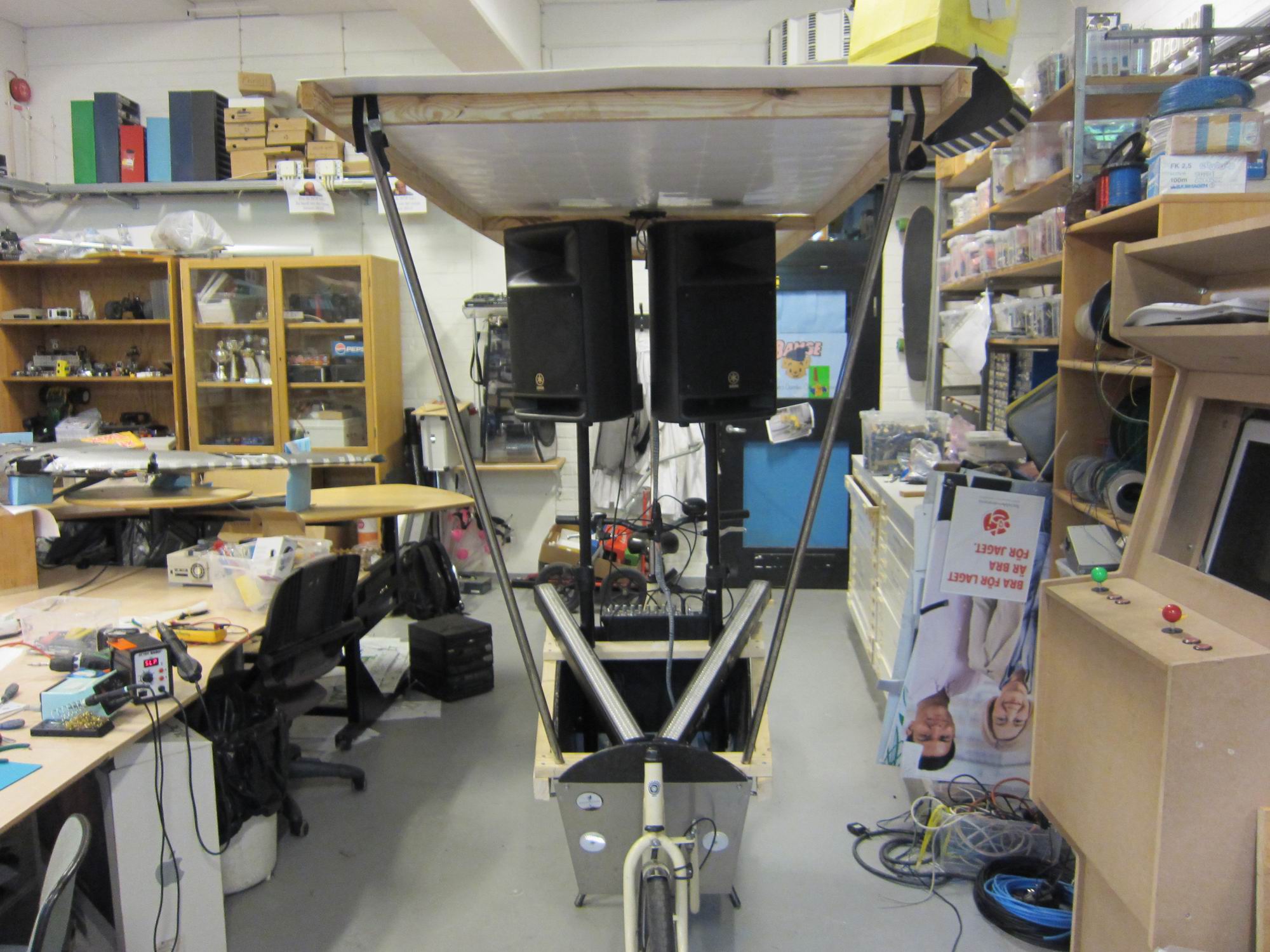
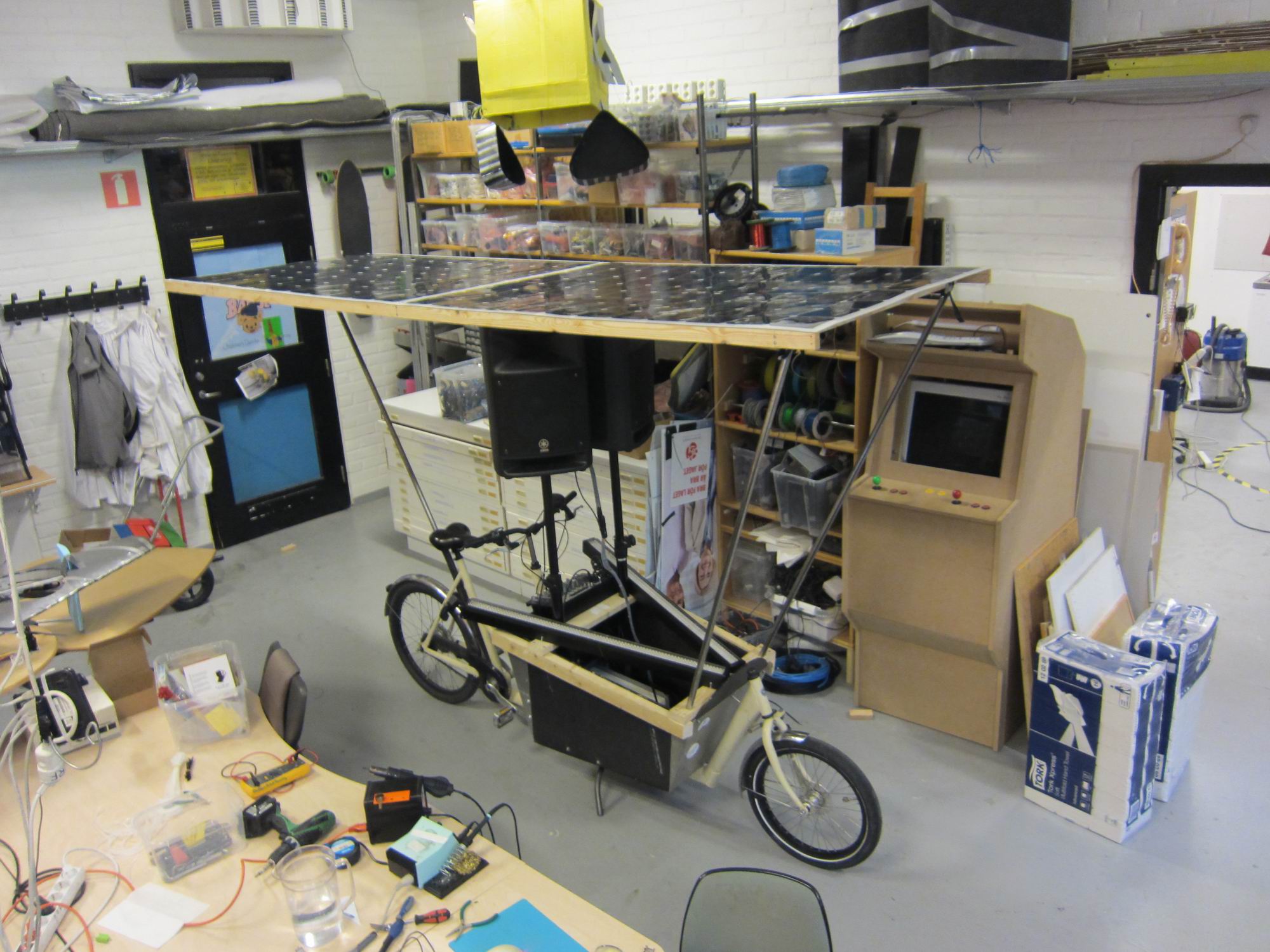
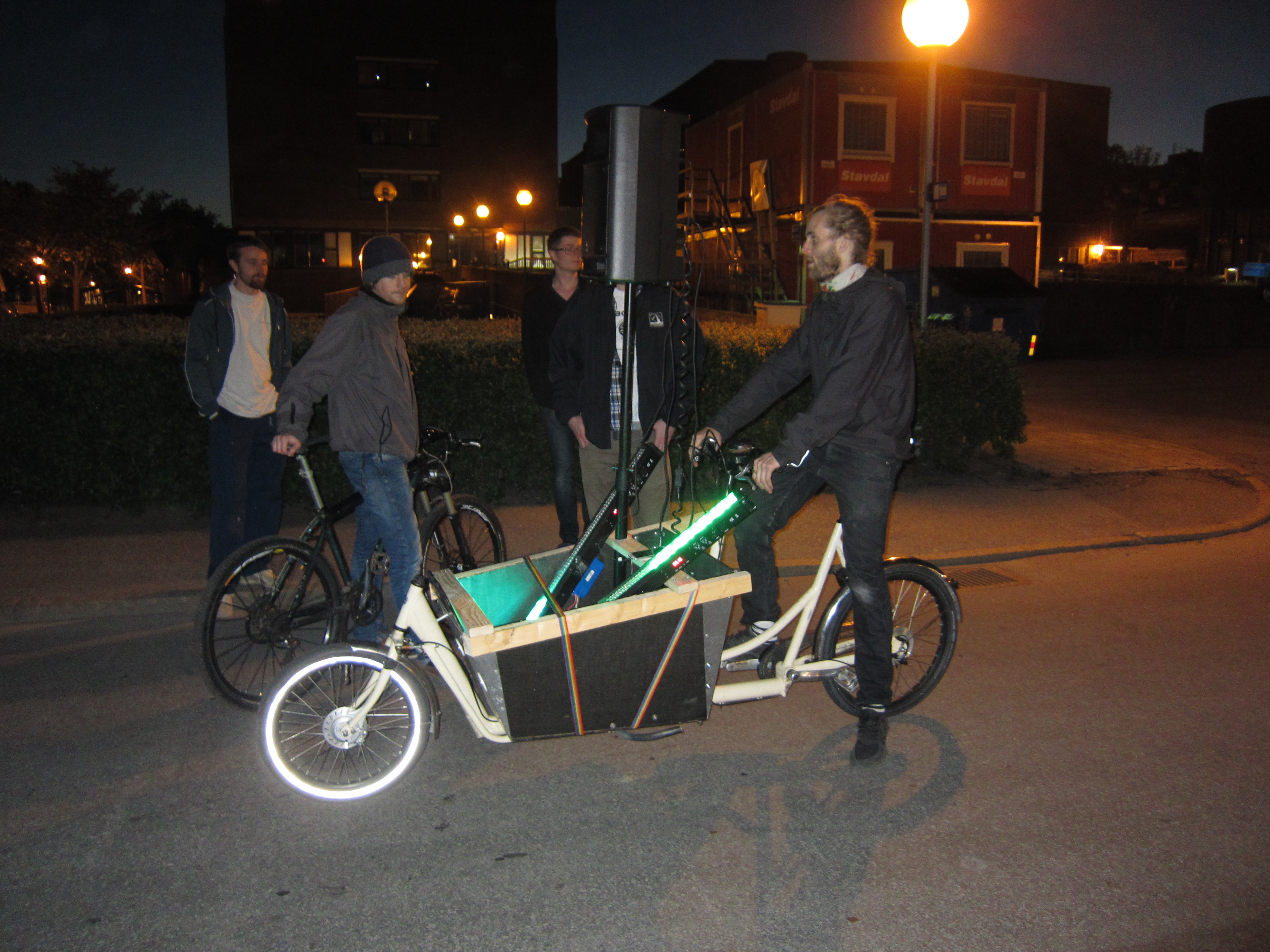
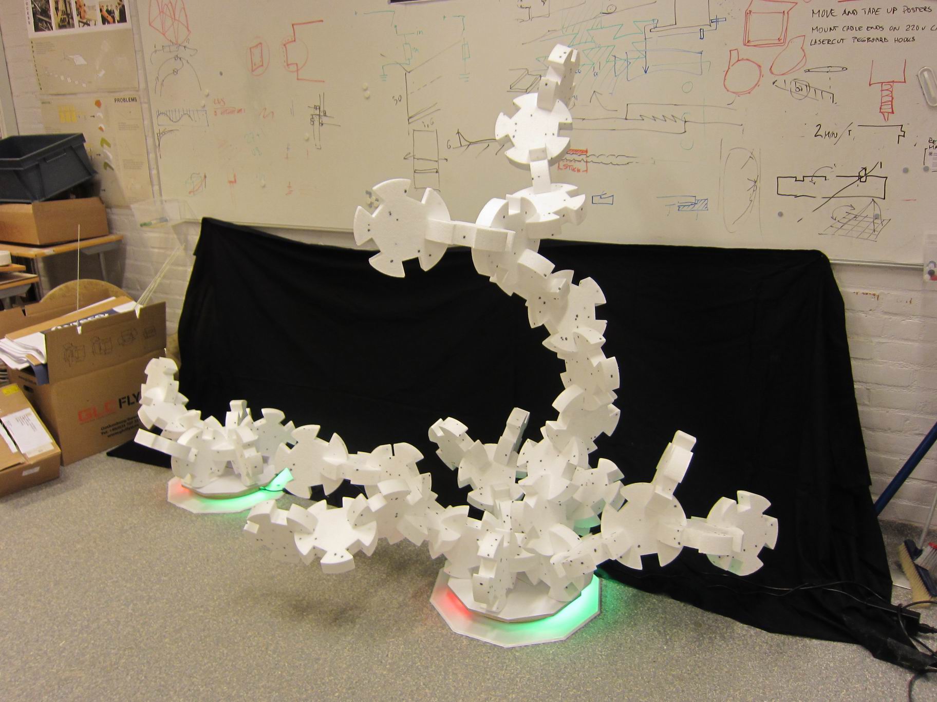
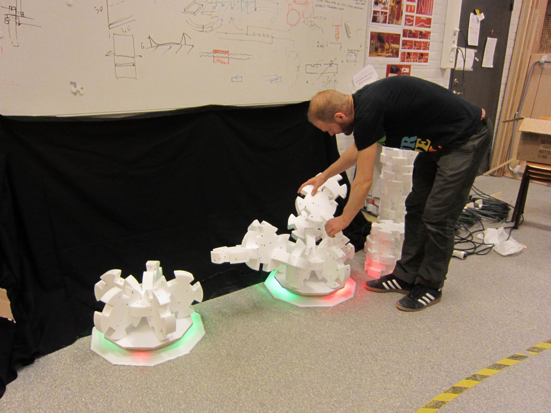
An interactive game were the visitors can build complex structure with help from an interactive LED balancer.
The installation was part at Vetenskapsfestivalen.

It’s a project by Stig Anton Nielsen read more about it in this post.

TeiSteadyBuilds from stig anton nielsen on Vimeo.

IMG_6645

A video posted by Tim Gremalm (@timgremalm) on

IMG_6638IMG_6643IMG_6644

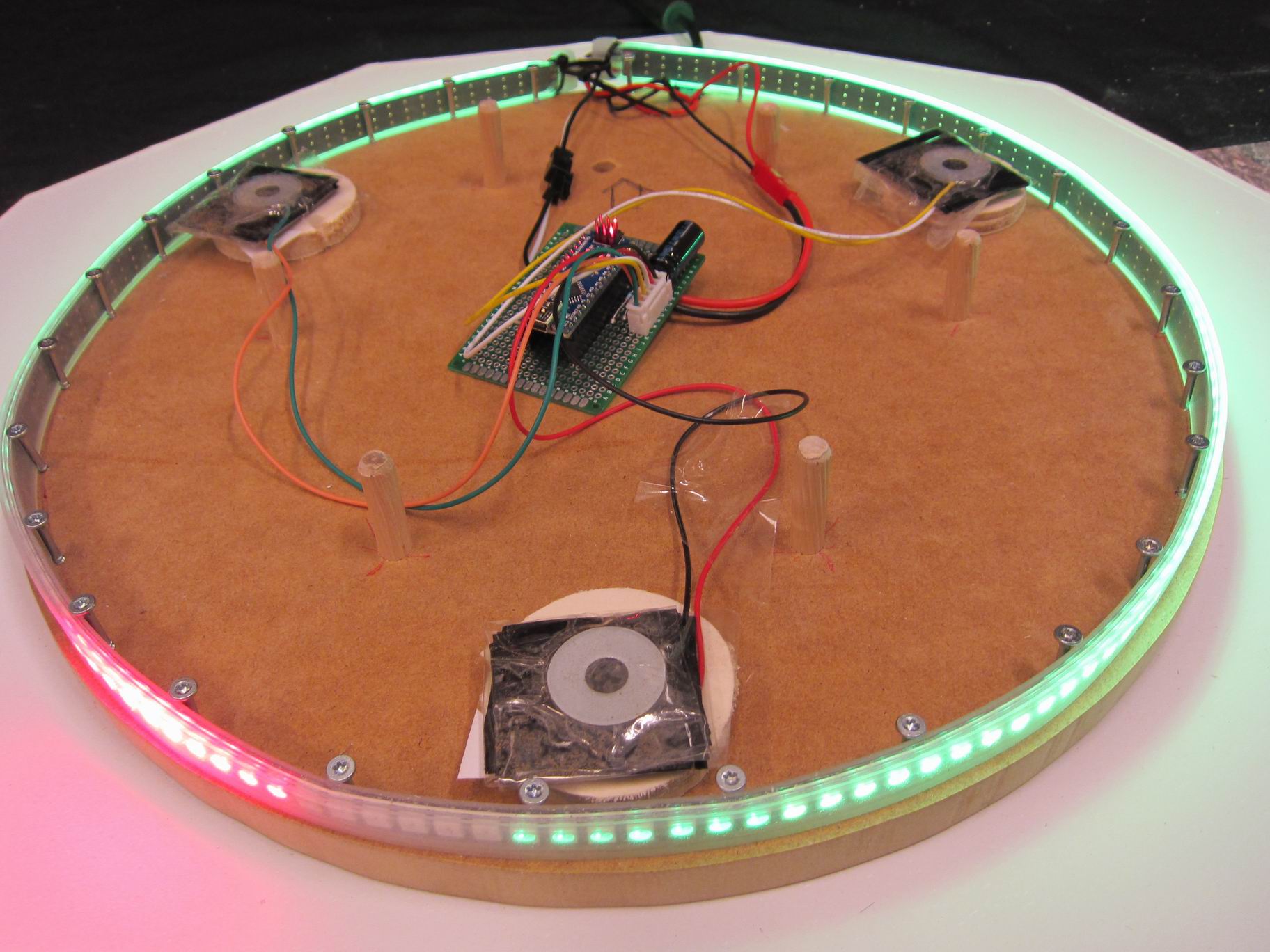
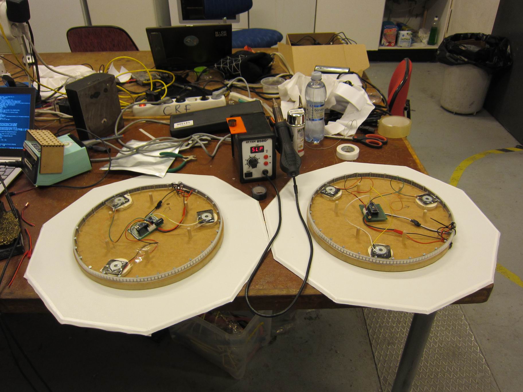
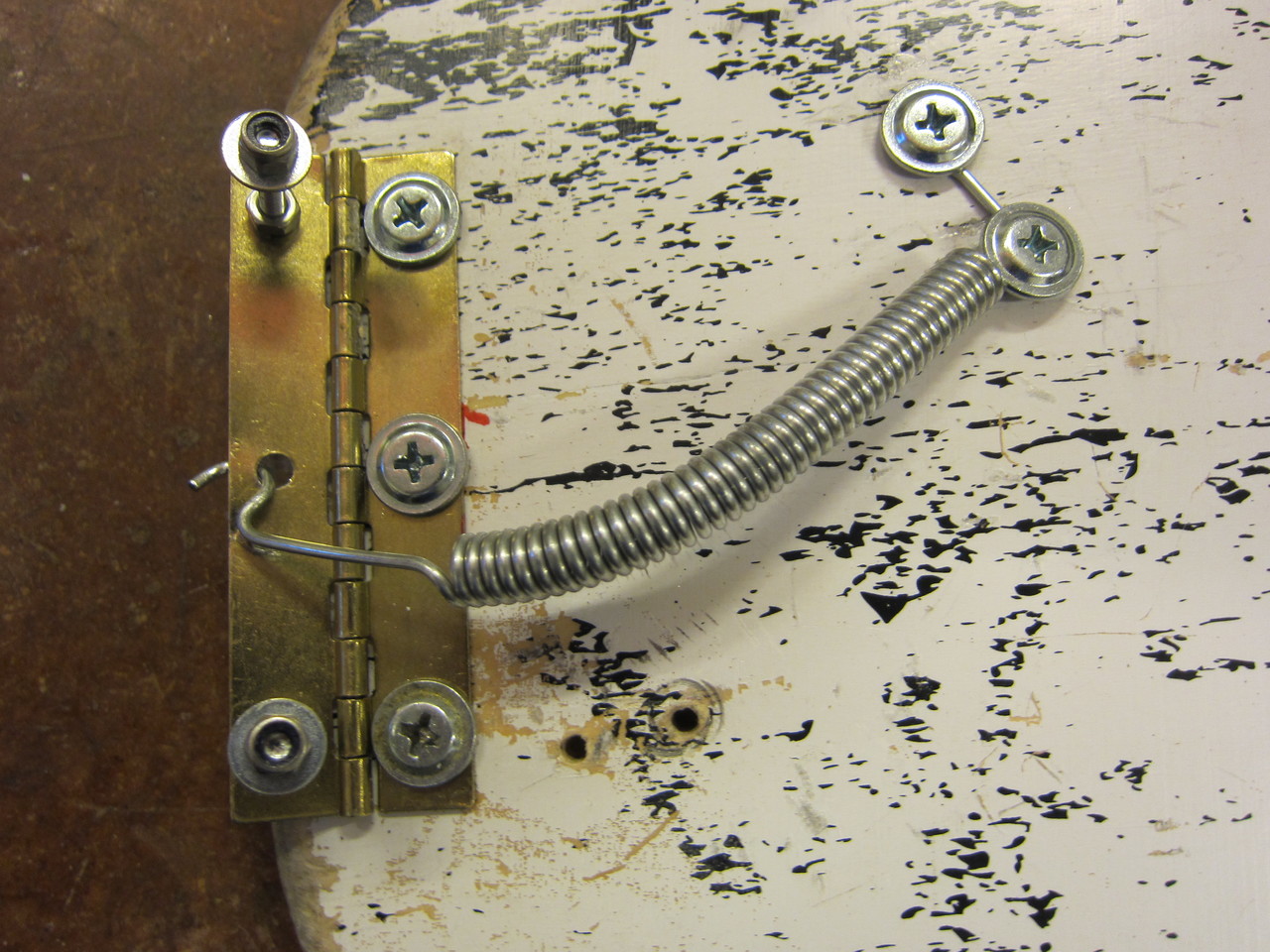
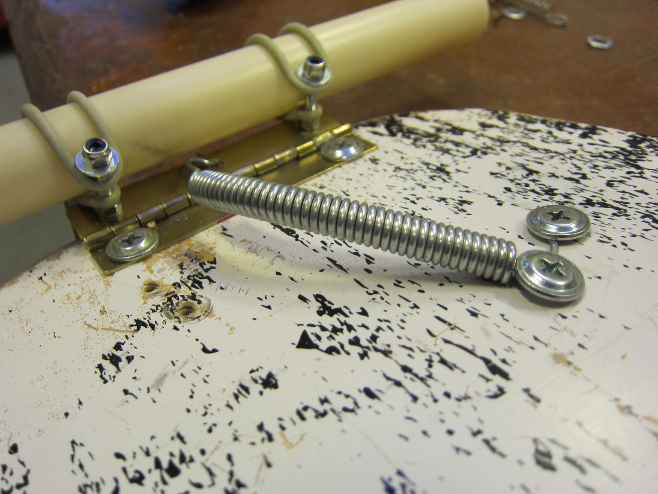
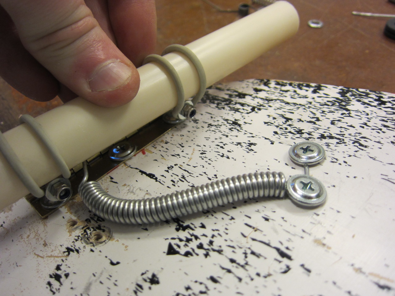
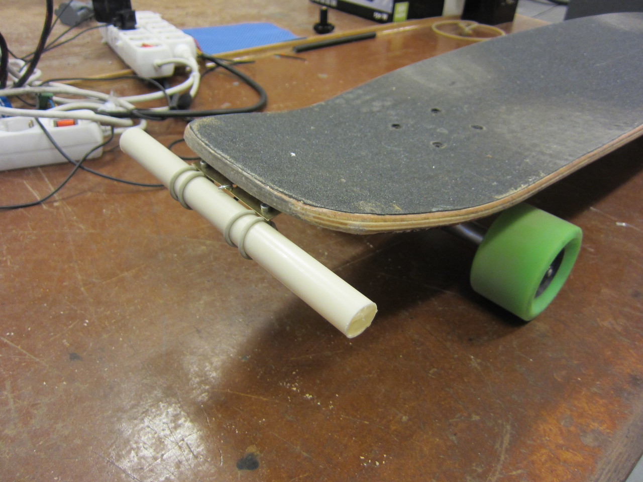
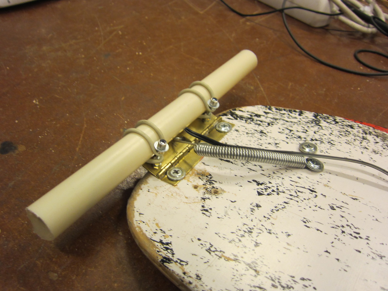
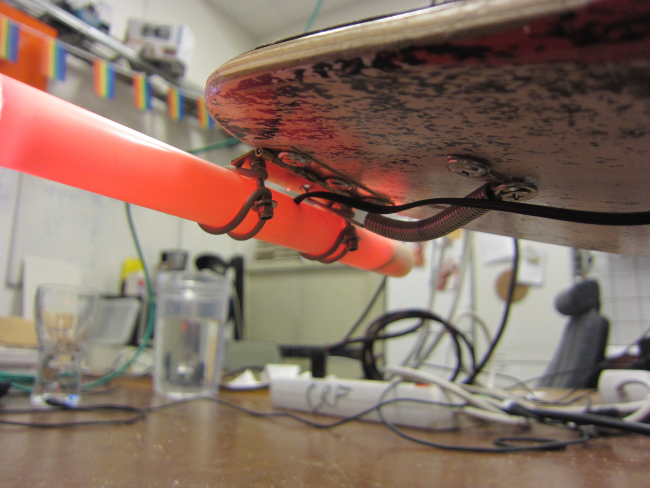
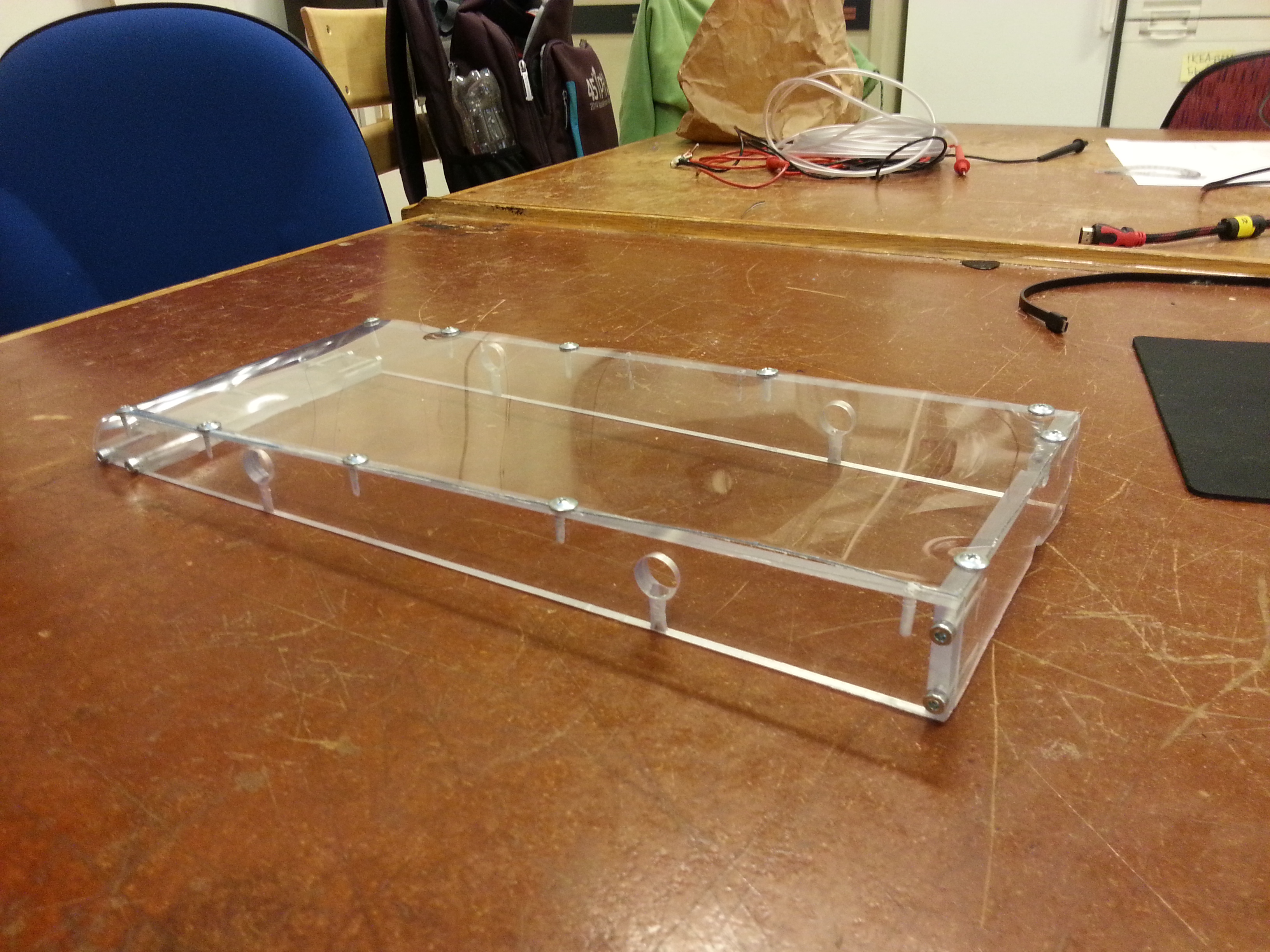
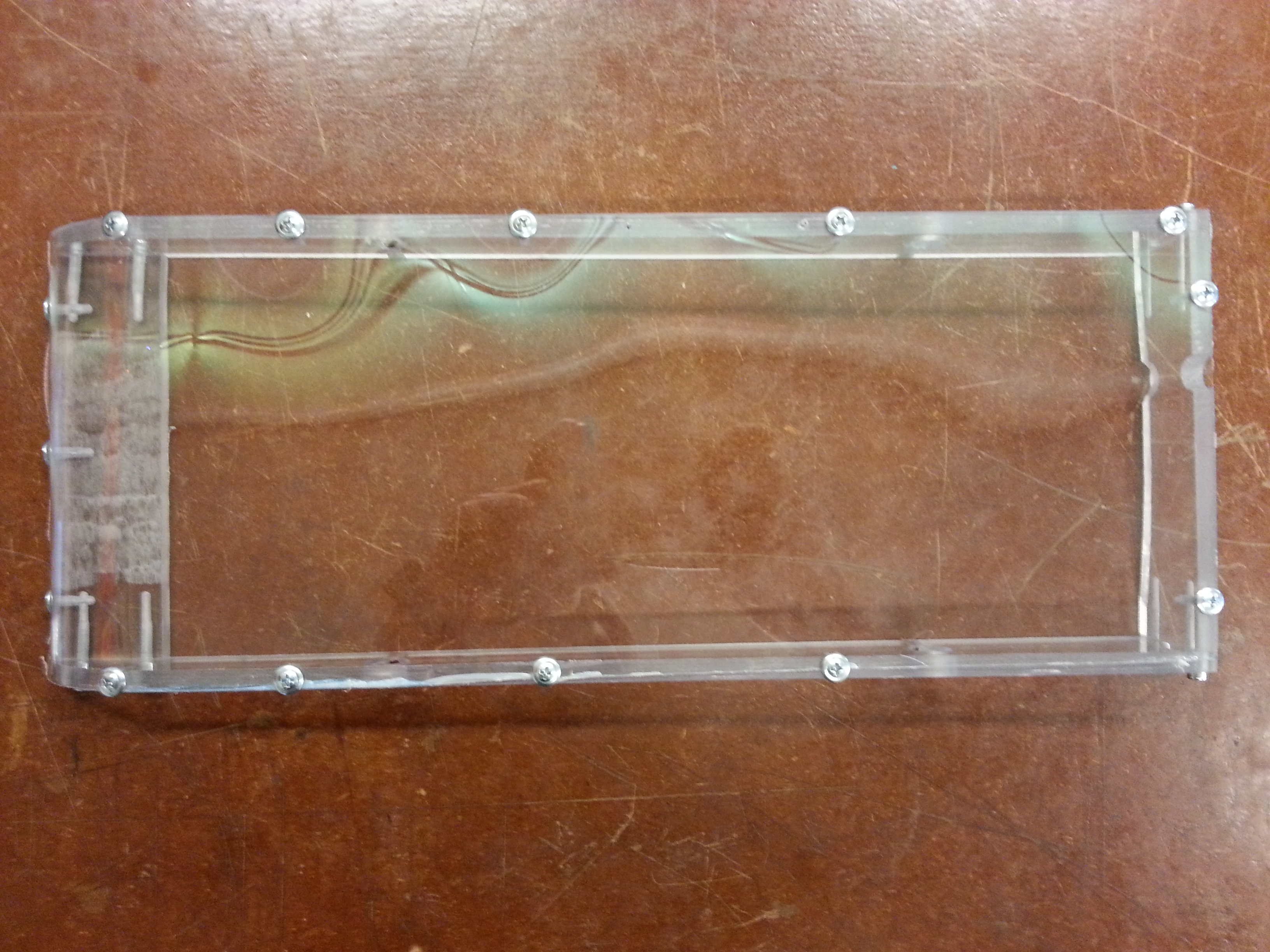
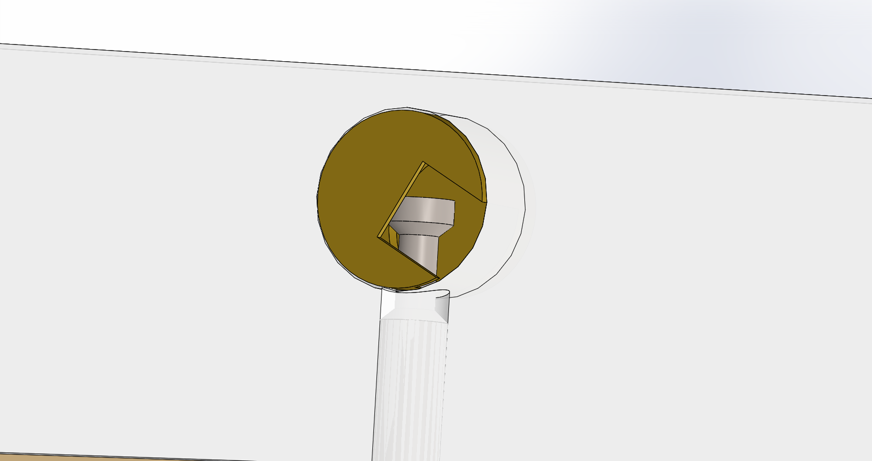
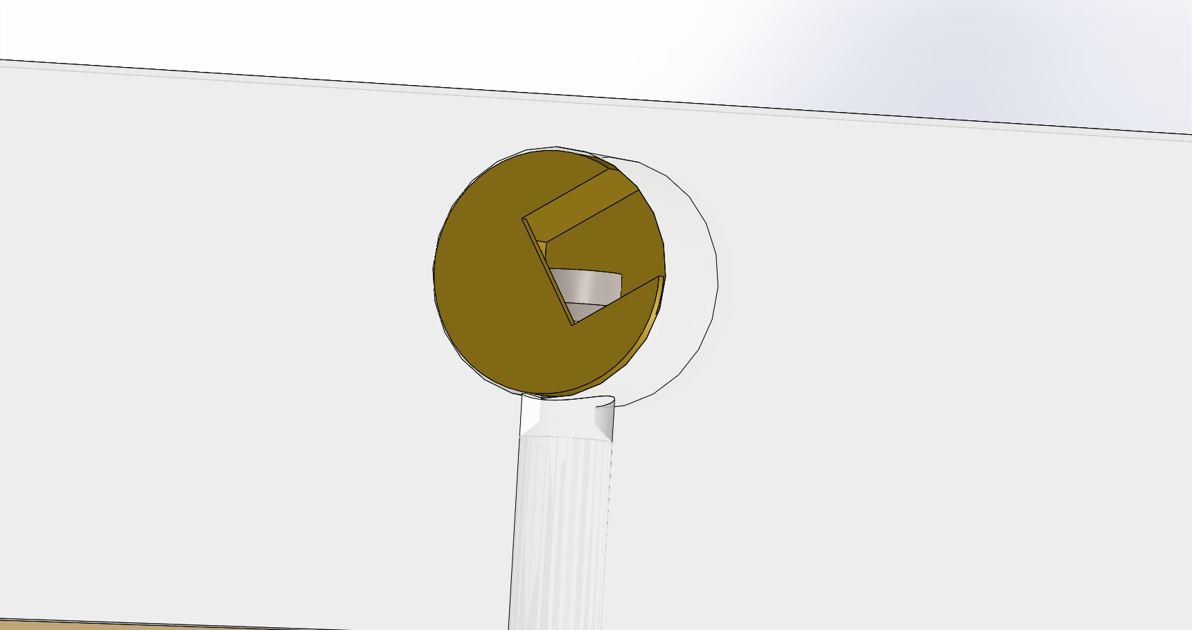
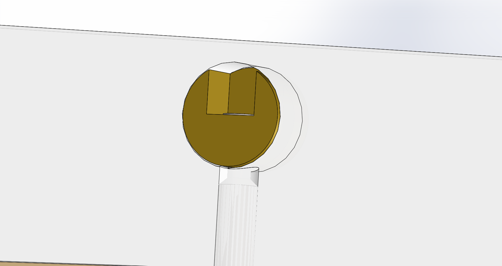
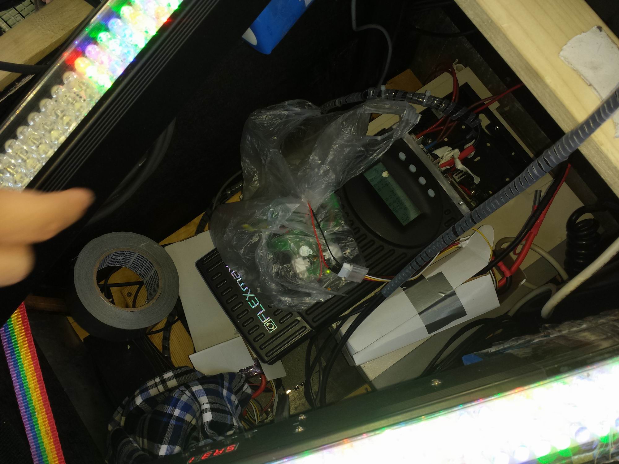
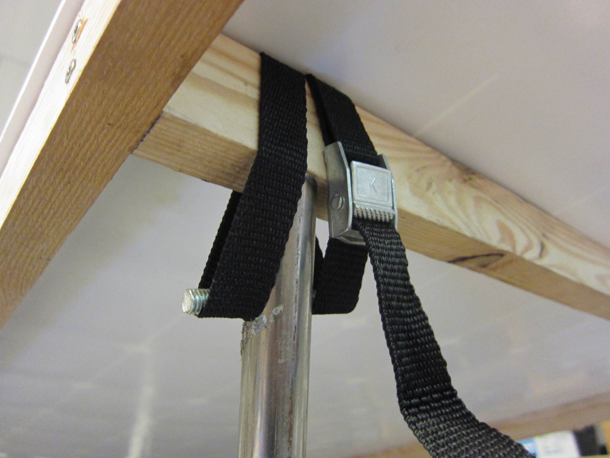
The loadcells is build from 16 layers of conductive carbon packaging film. The recistance ranging from 500k to about 450 Ohm loaded at 8kg. Because it’s a so huge range the loadcells can be directly hooked up in a voltage divider, no amplifiers needed.
3 load cells us used to detect the direction and force of the balance. They are really sensitive to touch, small pressures from fingertips will be easily detected. A backside is that the film tends to be squashed so that it takes long time form the form and resistance to return.
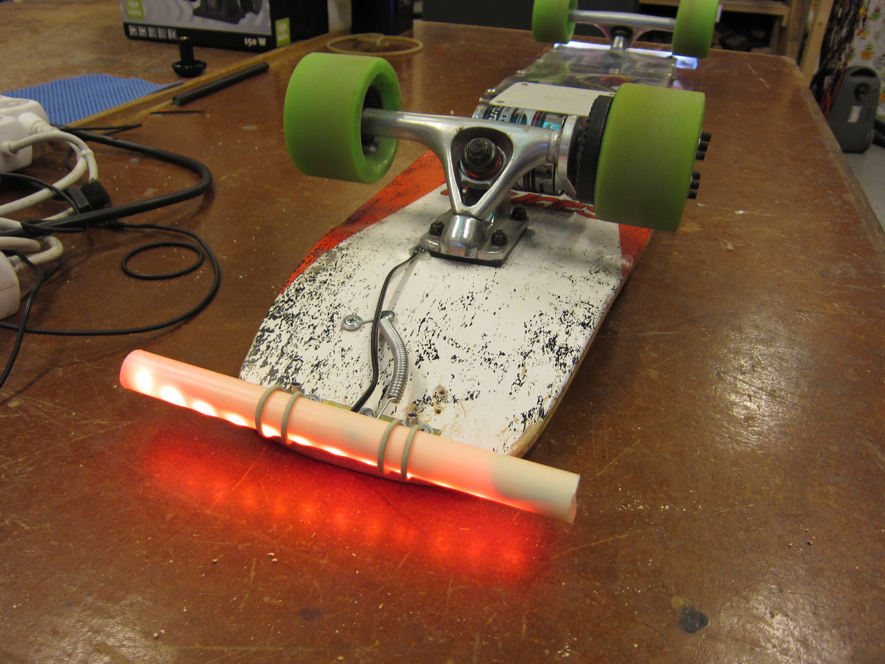
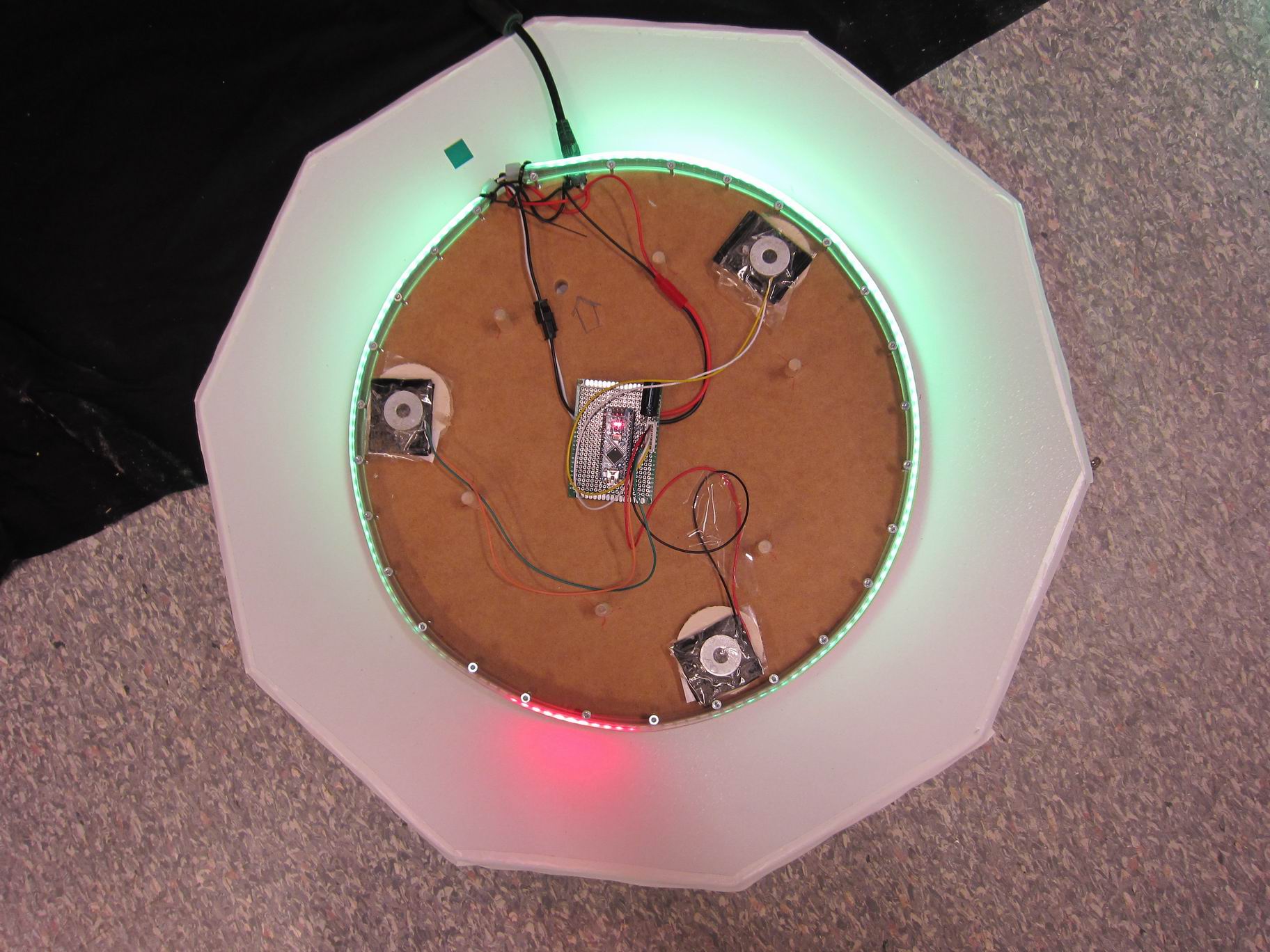
The value from the 3 loadcells is arranged in 3 forces 120 degrees apart. The Forces is calculated into a resultant that is describing a thrust vector.
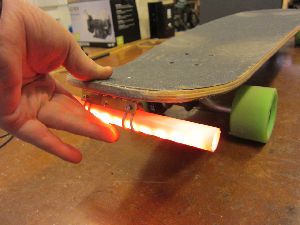
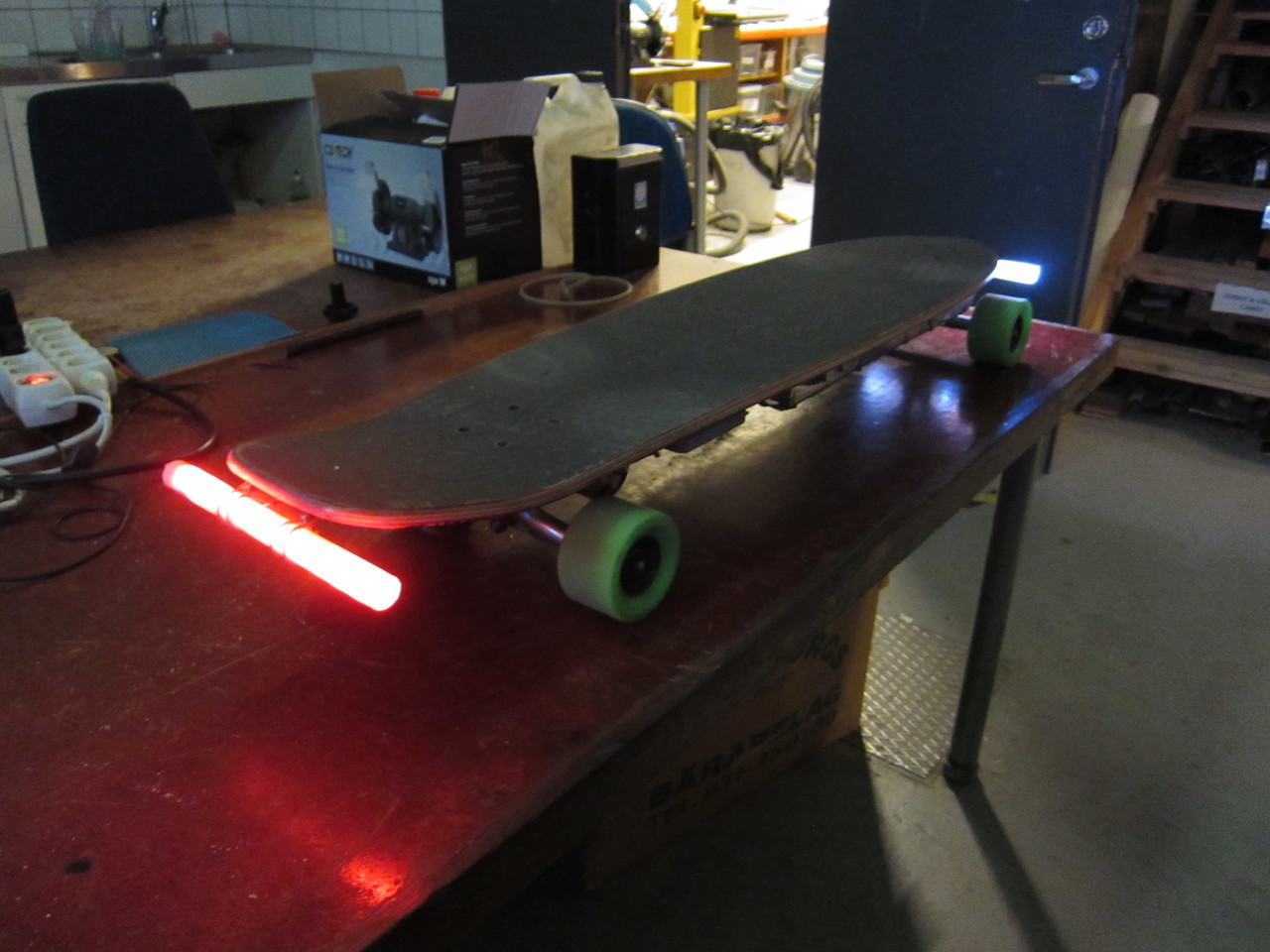
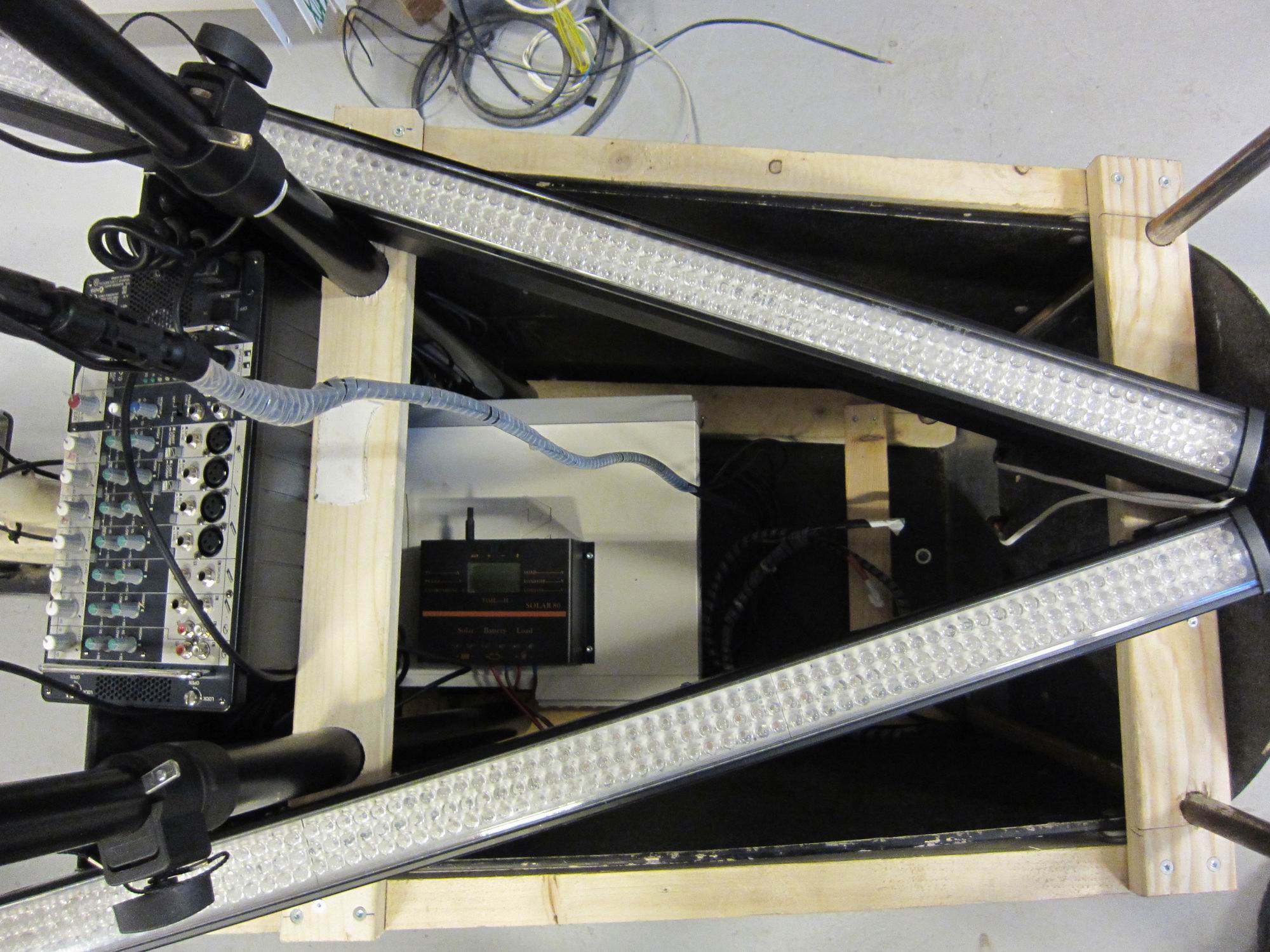
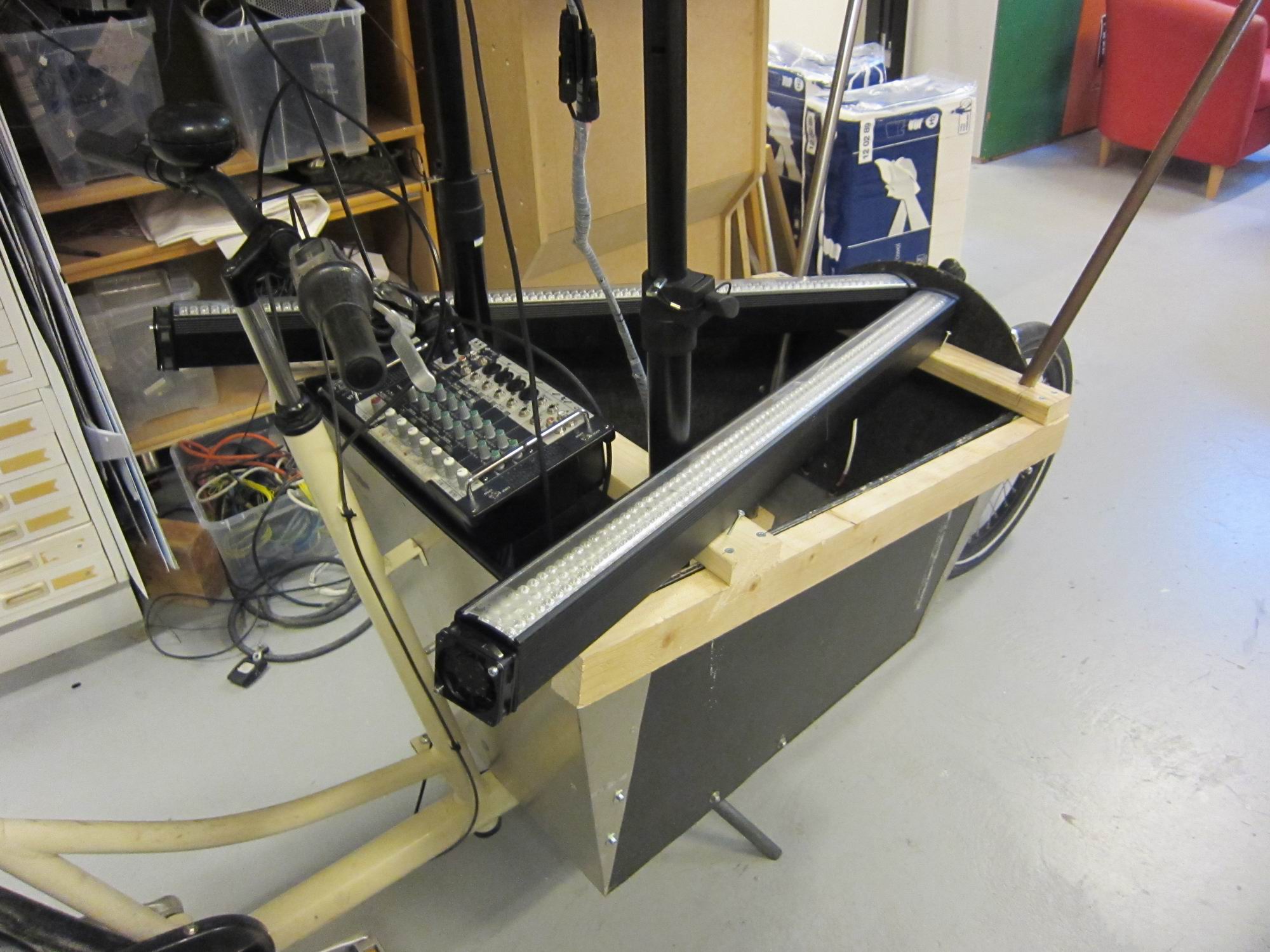
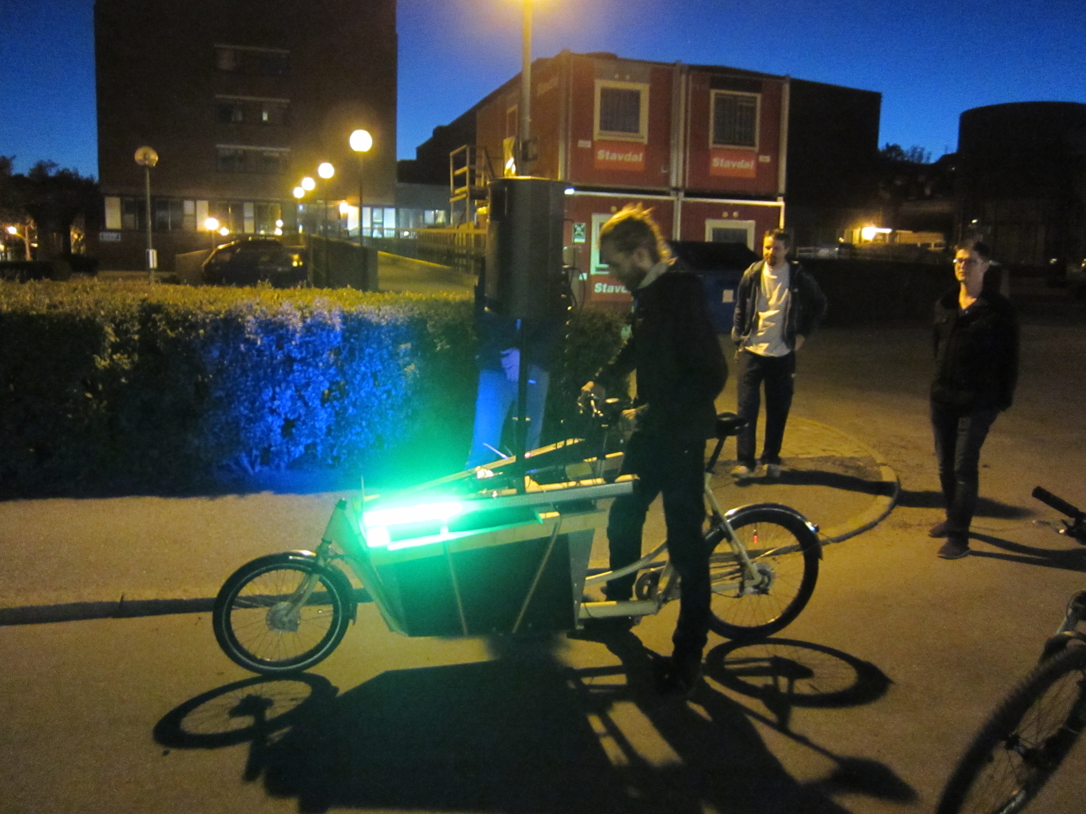
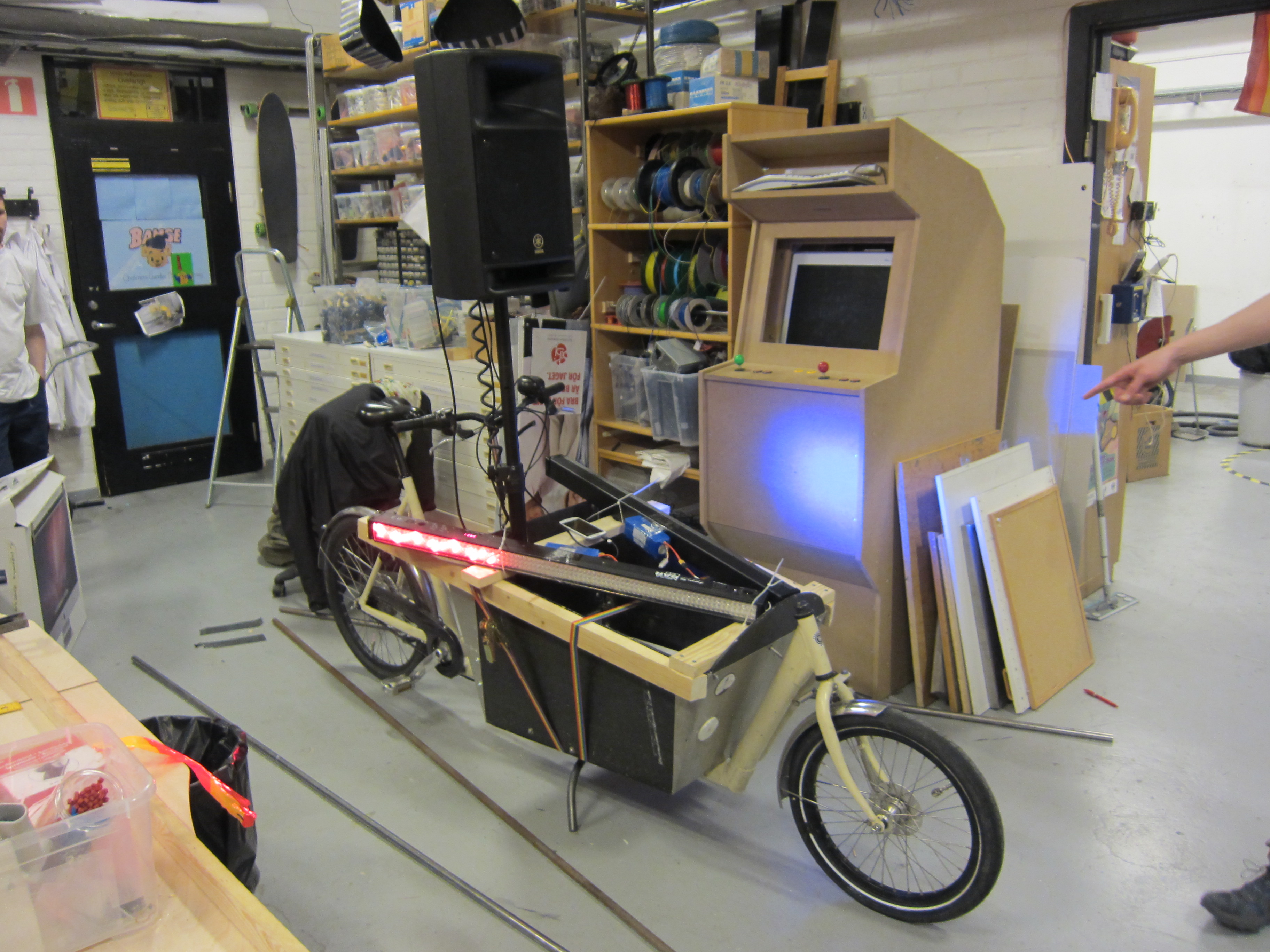
The thrust vector is indicated with a led strip of addressable WS2812 LED light. The stronger the force, more inbalanced, the greater the red marking will grow.

Att this Google Drive document I’ve collected som measuring data from the loadcells. There’s also some information of how the resultant is calculated.

Positional LED lights for Electric Longboard

IMG_6016.resized
I made some positional lights for my electric longboard to be able to be seen in traffic.

IMG_5970.resizedIMG_5972.resized
The rear red light have to be able to fold in when the board is placed on its butt.
A hinge was mounted, and a spring is holding the light tube up.

IMG_5965.resizedIMG_5966.resized
IMG_5964.resizedIMG_5996.resized
White electric tubing is used to protect a LED-stripe from dirt, it also diffuses the light.

IMG_5987.resizedIMG_5990.resized
The LED-stripes is powered by a buck converter, switching the voltage down from 25V to 12V.

IMG_6000.resizedIMG_5998.resizedIMG_6010.resized

IMG_6005.resizedIMG_6006.resizedIMG_6007.resizedIMG_6013.resized

Battery Chassis for Electronic Longboard

IMG_0001
IMG_0002IMG_0003IMG_0004IMG_0005IMG_0006IMG_0007
To have the LiPo battery’s exposed underneath the longboard could damage them if something hit them. A strong chassis for the battery’s would protect them, as well as covering the cables from dirt.
The chassis is primary made out of 8mm polycarbonate, with a sheet of 1mm flexible PET cover.
The 8mm thick sides will hopefully take up the forces from any direct bumps.

CAD Drawings

IMG_0008IMG_0009
CAD-files (Zipped Solidworks and DXF)

Cam Lock Screw

IMG_0010
IMG_0011IMG_0012IMG_0013IMG_0014
For locking the chassis to the board I used cam lock screws, the same that is often used in IKEA furniture.
The cam lock seems to come loose due to vibrations, so another solution might be needed.

CyckelLjudet & Festmaskinen at Regnbågsparaden West pride Göteborg

IMG_1012
After assembling CyckelLjudet we managed to arrive at Götaplatsen were the parade Regnbågsparaden were supposed to start.

The solar panels worked really great, we had no trouble at all and the LiPo was charged nicely.

We did use an old Sennheiser wireless transmitter to send the audio from the DJ-booth at Festmaskinen to the PA-speakers at CyckelLjudet.
We had some problems with wireless interference, but it hold up well most of the parade. Go 80’s technology!
IMG_1000 IMG_1001 IMG_1002 IMG_1003 IMG_1004 IMG_1005 IMG_1006 IMG_1007 IMG_1008 IMG_1009 IMG_1010 IMG_1011 IMG_1013 IMG_1014 IMG_1015 IMG_1016

CyckelLjudet – Attaching electronics and solar panels

IMG_0012
All pimped out and ready for the west pride parade Regnbågsparaden!

IMG_0010 IMG_0009
To be able to drive the amplifier for the speaker we use an UPS. On top of the UPS you can see the solar regulator Solar80.
The solar regulator is charging a 6S 8Ah LiPo battery pack. The solar panels will generate maximum of 600W of power, and the PA-system will draw about 65W of power, so the battery will be more of a buffer.

IMG_0011
After some spec-readings we realized that the Solar80 wouldn’t handle the maximum of 70V that the solar panels could generate, it only supported 48V. So we switched it out for Flexmax 80.
Both the controllers were designed for lead-acid battery’s and not for LiPo battery’s. I was missing a parameter to set the charge voltage, also there was software limitations that you couldn’t go around, like the charging current for example, you could only go as low as 5A.
We’re trying out the solar panels and solar regulator in the sun charging the LiPo. The stop-charing-limit was set to 25.2V which is the voltage of a maximum charged LiPo, but the solar regulator was still inputing voltage well above 25.2V because the solar regulator is designed for lead acid battery’s. We then set the maximum-charging-voltage to 24.8V that seemed to help, the voltage over the battery didn’t reached over 25.2V.

IMG_0008
Cables from the solar panels.

IMG_0007 IMG_0006
Amplifier/mixer in place, and so is the LED-bars.

IMG_0005 IMG_0004 IMG_0003 IMG_0002 IMG_0001 IMG_5570 IMG_5568 IMG_5565 IMG_5563