The ultimate Microbit Set


I made the ultimate Microbit set for my purposes. I combined several kits in to one kit, and also included a ES121 electric screw driver and tweezers.


These are the original kits that I combined to get multiple bits.


I found a good sturdy case for fishing flies.


I found out that a common laser cut friendly foam is polyethylene foam (PE foam or PEF). It’s commonly used for tool cases.
I calculated all the bits I wanted, and made slots for them together with some of my tools. Then I laser cut them out and hot glued them into place the case.


The end result is an awesome Microbit set that is very portable.

Prop for Downton Abbey larp


For the larp 1912 we wanted to have servant bells like in Downton Abbey.


Carl Nordblom made a nice looking construction for the bells using leaf springs.


An ESP8266 is listening on some bell topics for messages. If a message is received it will swing the corresponding servo with a bell hooked up.


To trigger the bells we built a box with a auto returning string to pull. The strings is hooked up to a micro switch witch triggers the reset pin on a ESP8266.
When the ESP8266 starts it sends a message on the corresponding MQTT topic to ring, then enter heavy sleep mode.

Skrivbord – An overengineered workstation


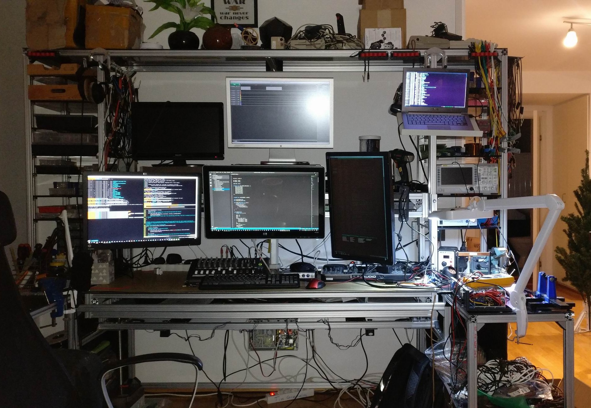
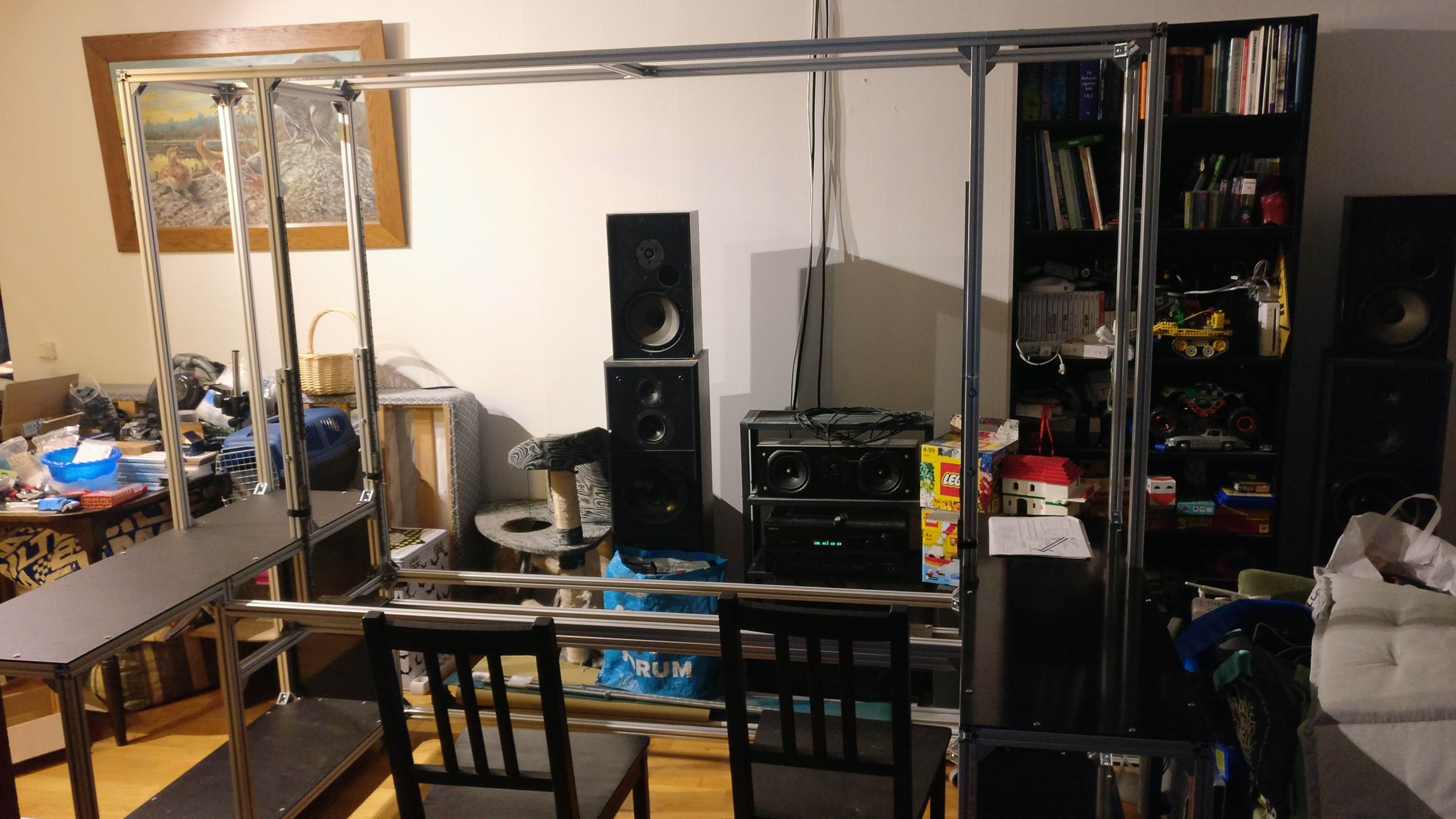
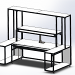
So I have wanted to build a desk for many years now, ideas have grown and so has the big feature list. But since my interest have moved away from software to electronics my requirements have changed. I need a lot bigger work space for tools and more shelves for instruments, and still a lot of screens.
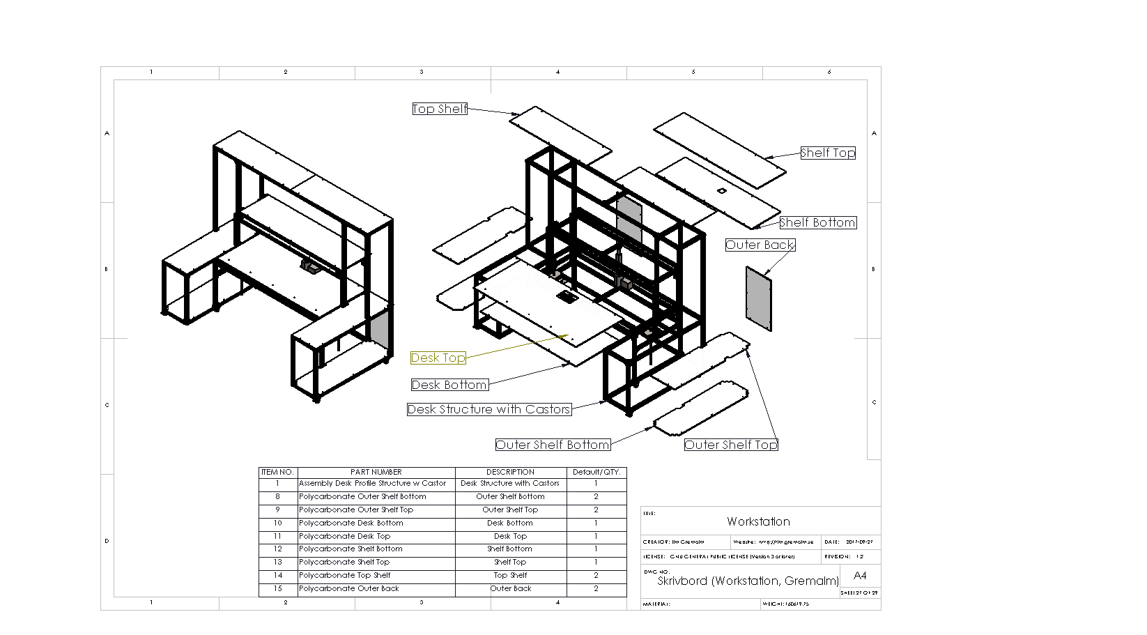
So 3 years ago I started on my desk design. I decided that I wanted to go for aluminium profiles for my frame, both because it’s flexible and something I had not tried it before.
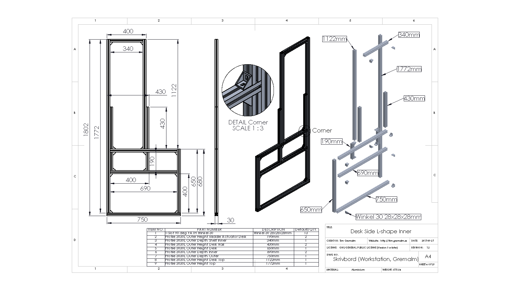
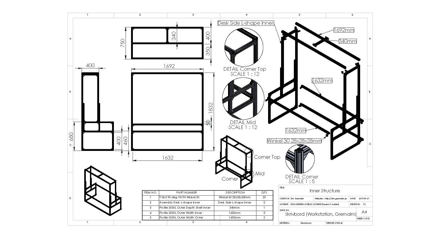
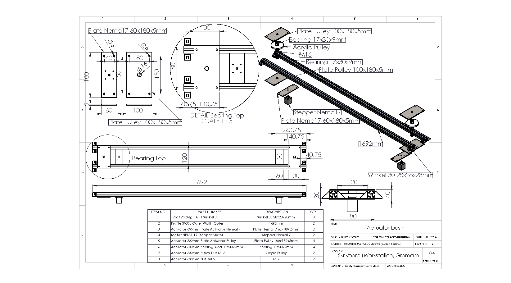
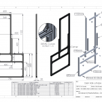
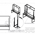
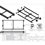
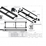
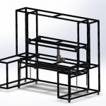
I also wanted as much of the construction to be as precise as possible, so everything is constructed in CAD. Mechanics strength tested, mechatronics is movement tested, material purchase planned and material is CNC cut as much as possible.
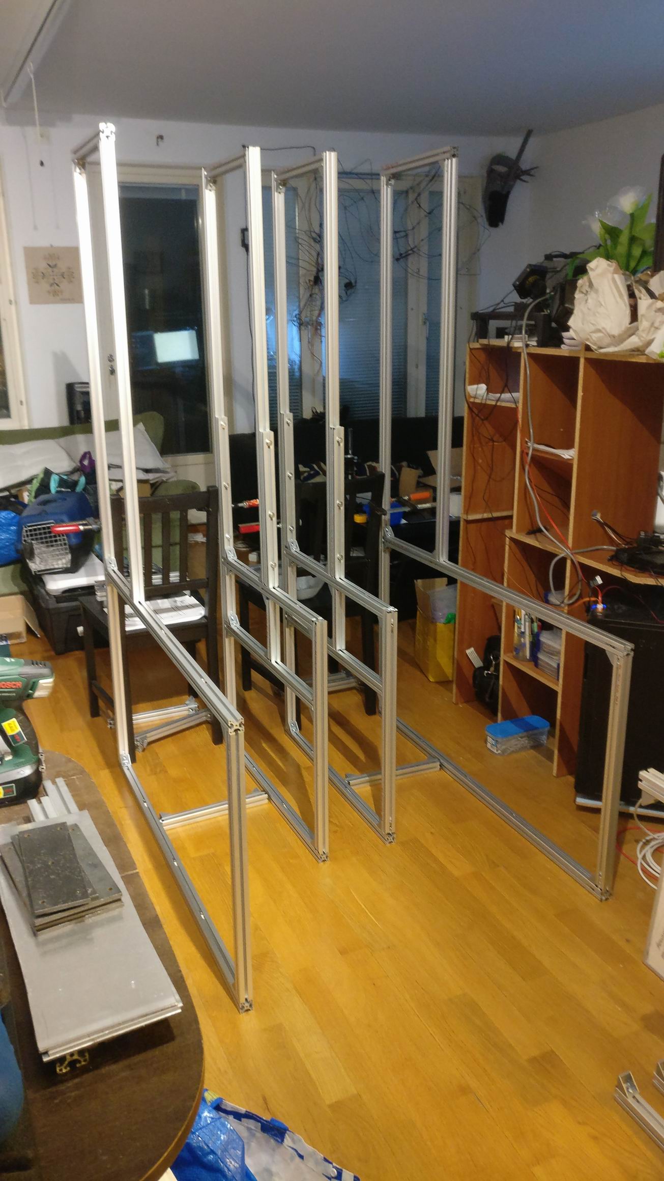
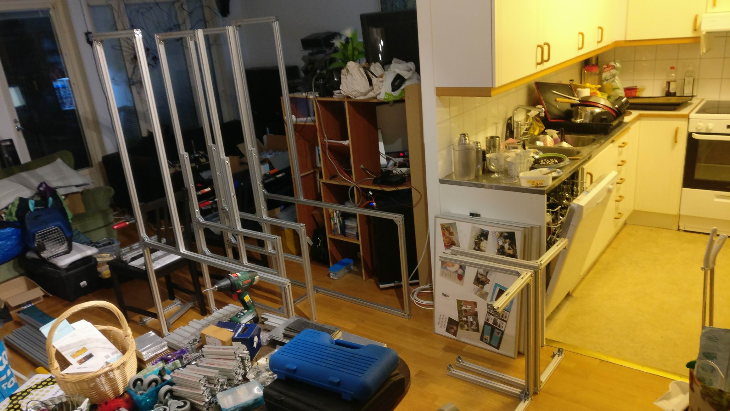
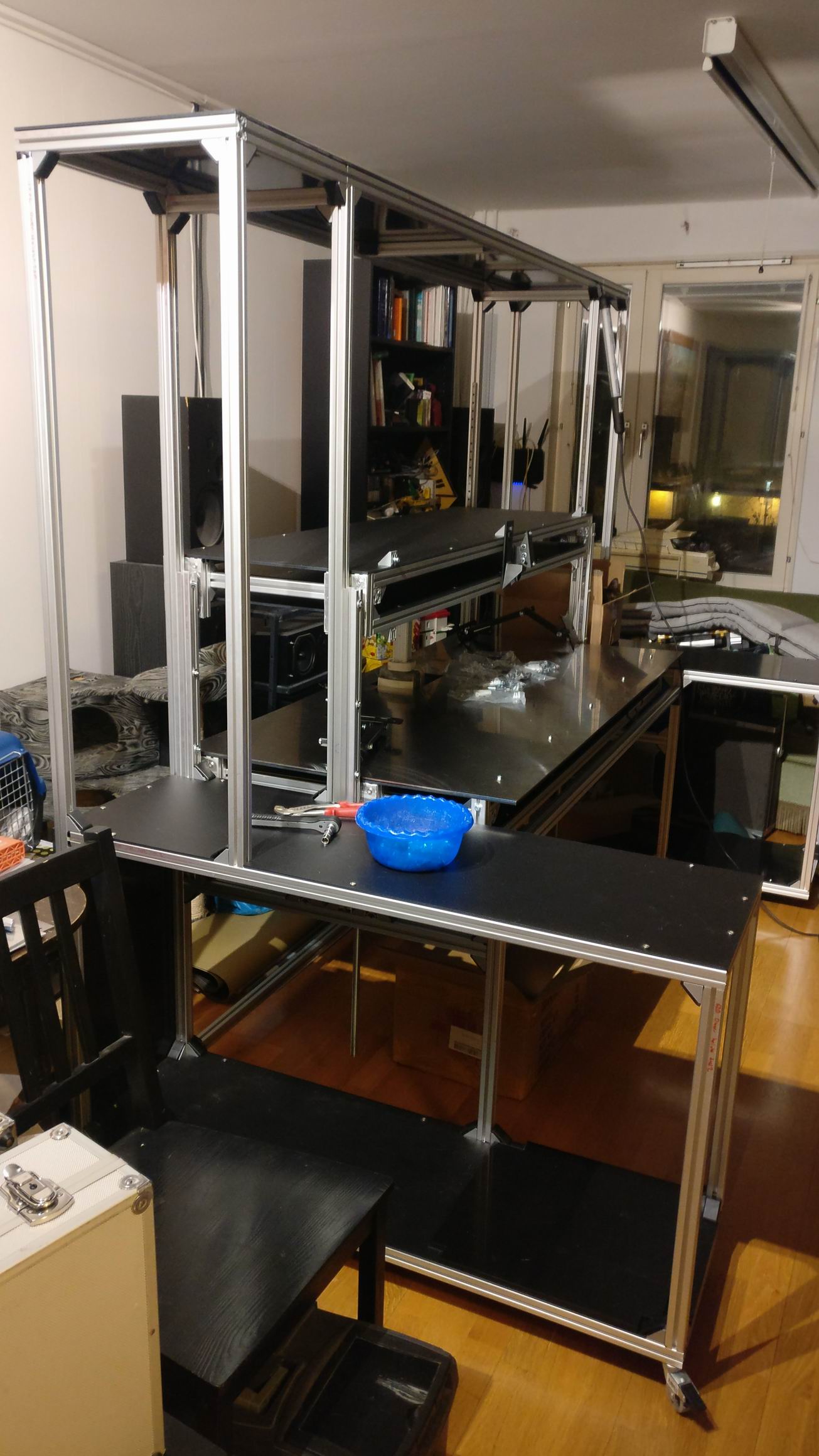
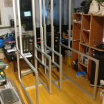
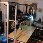
By the end of 2018 I started the weeks long process of assemble it all.

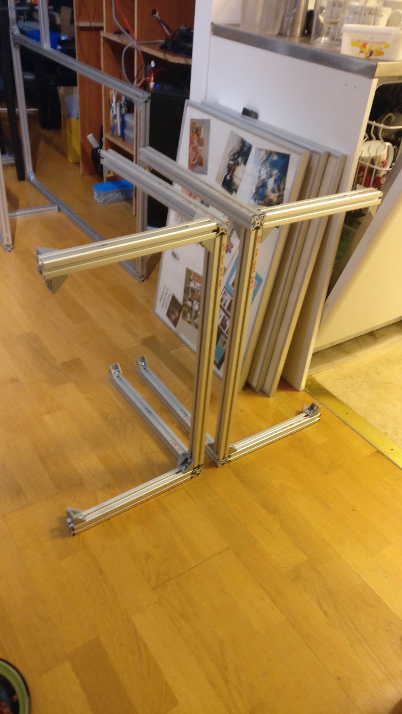
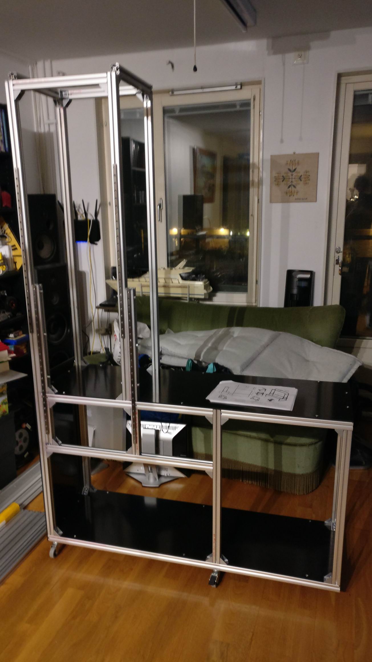
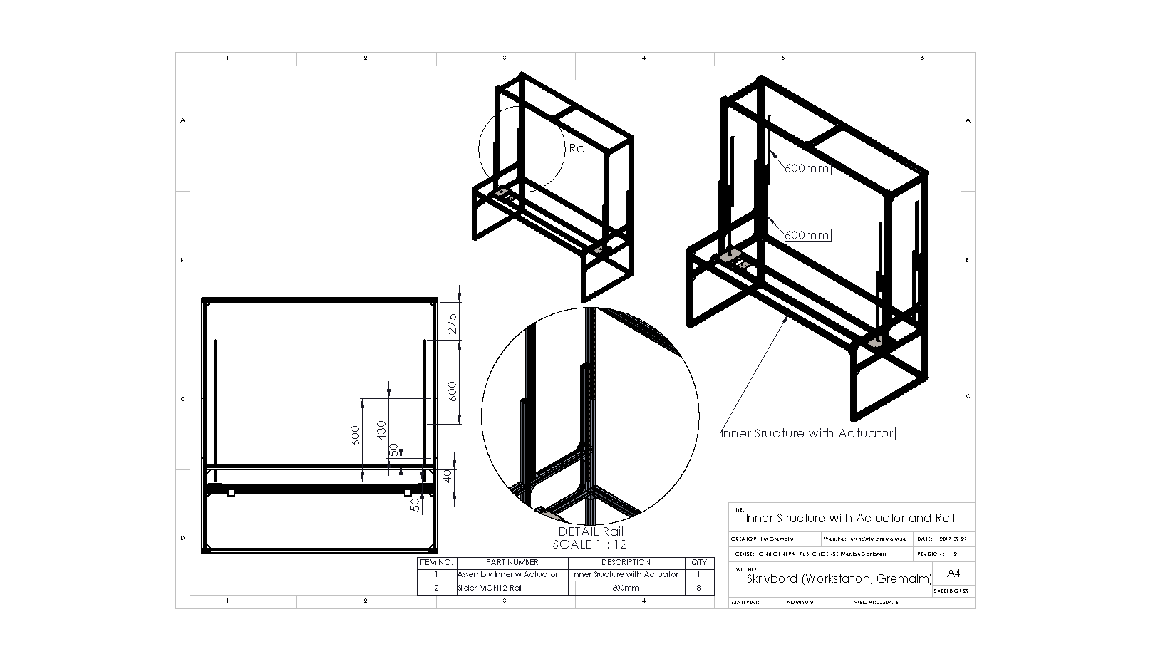
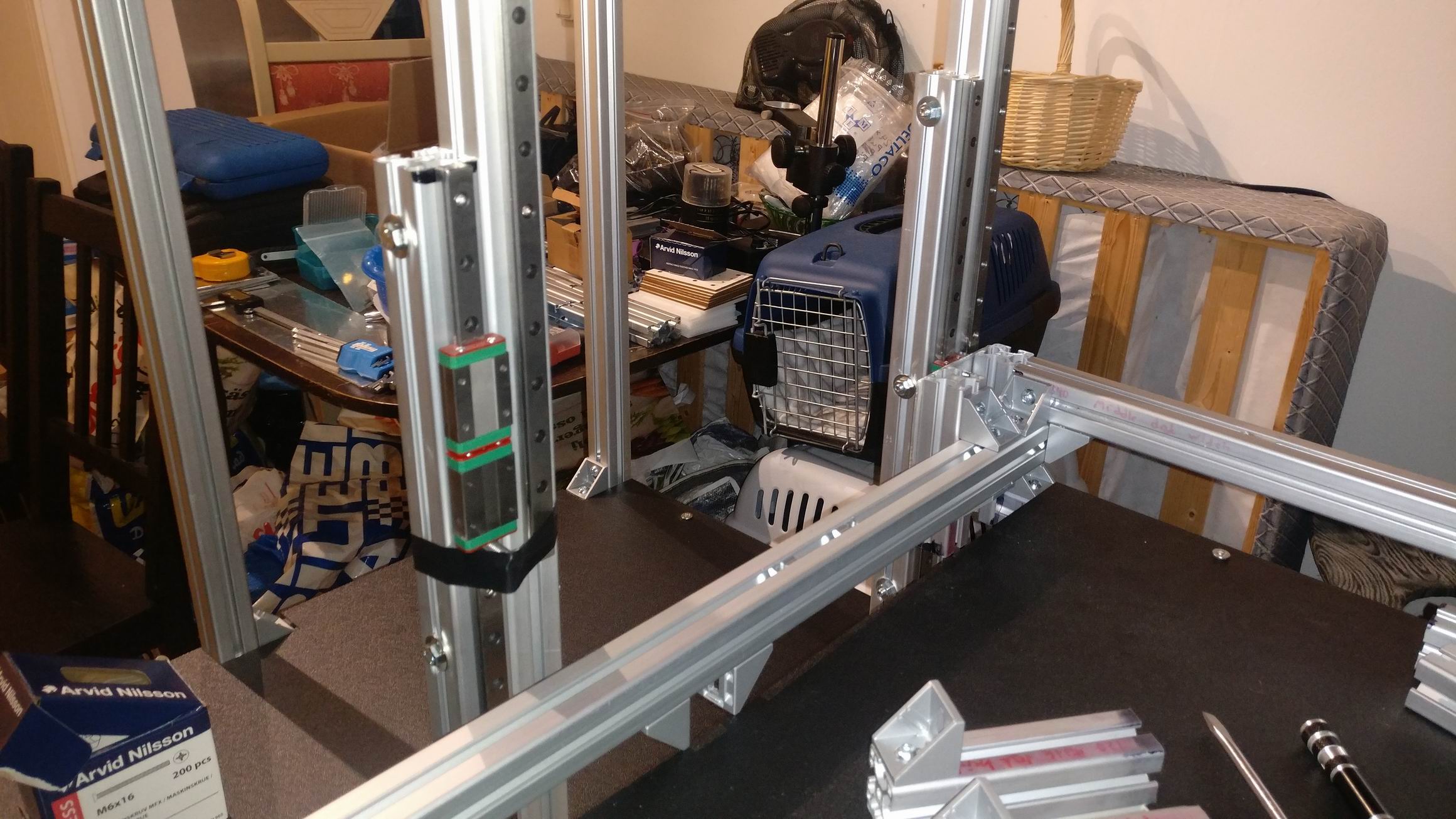
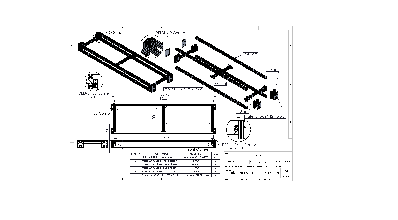
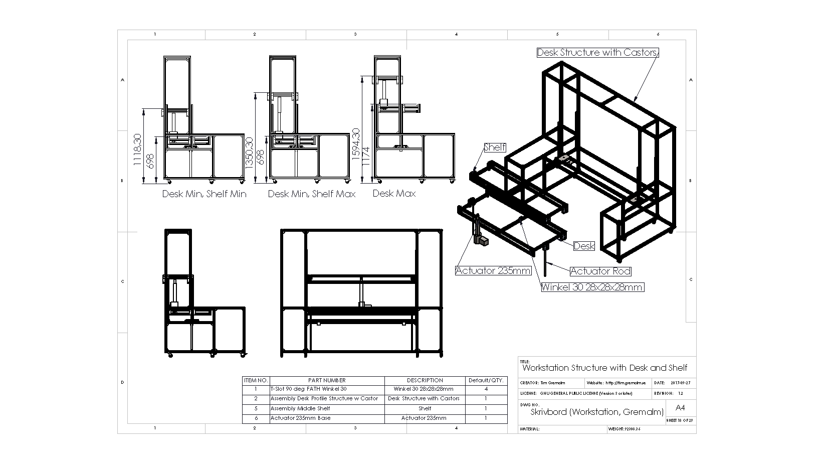
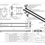
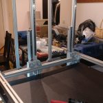
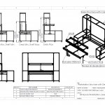
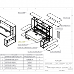
I made a drawing with assembly instructions based on my CAD design Skrivbord (Workstation, Gremalm).pdf. But I quickly decided to change the assembly order to make two stable outer pieces to build the rest on, it also meant that I didn’t have to turn the whole assembly too much.


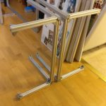
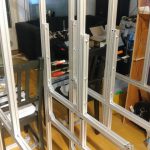
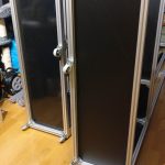
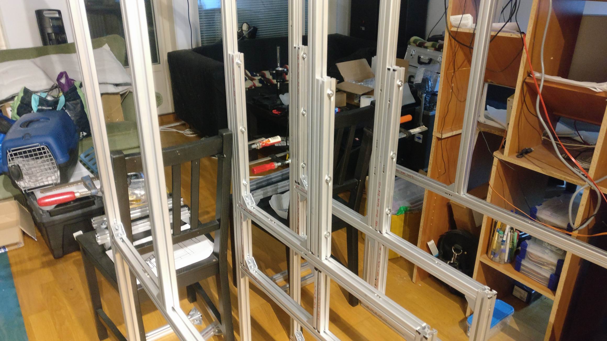
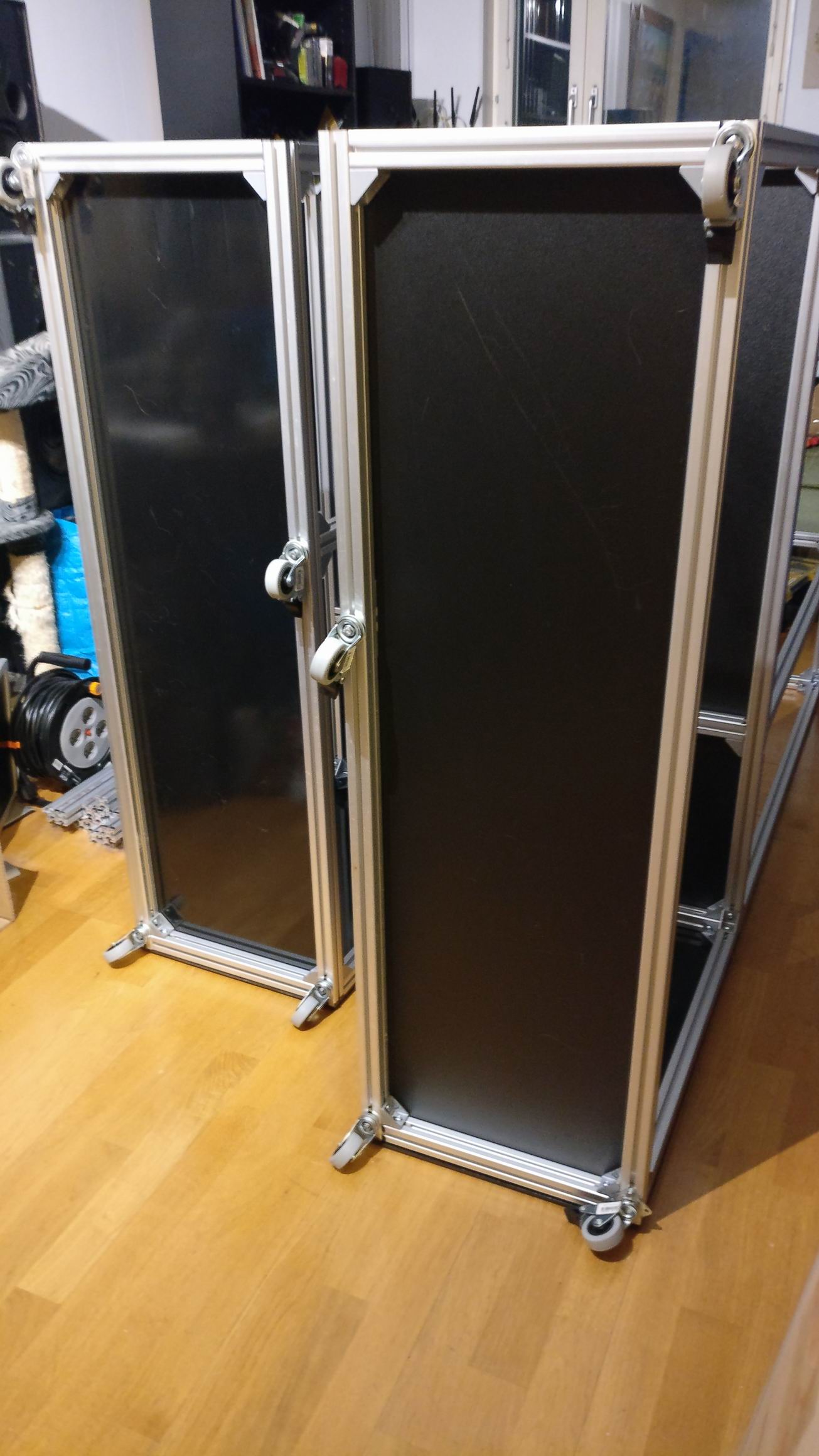
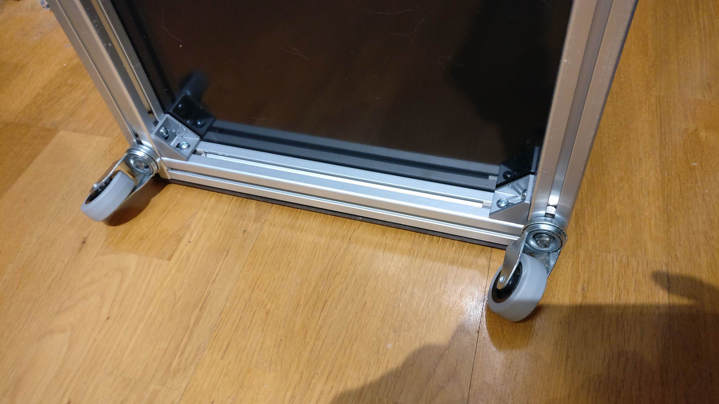
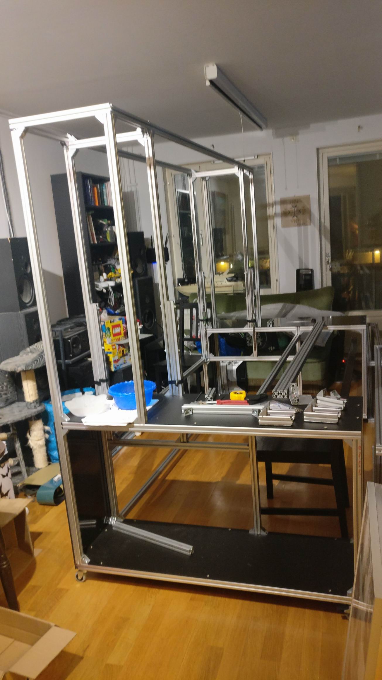
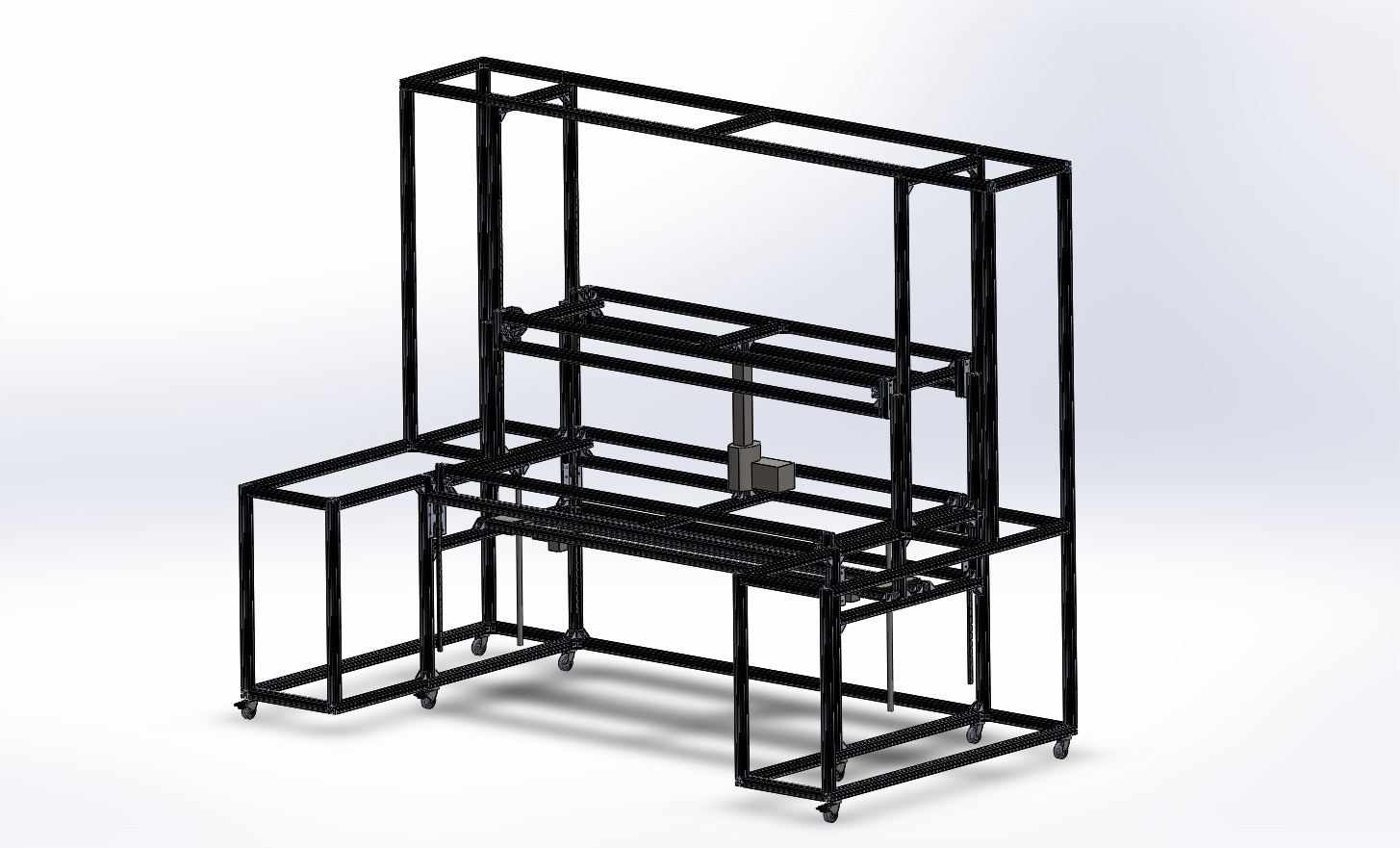
The two outer pieces assembled.


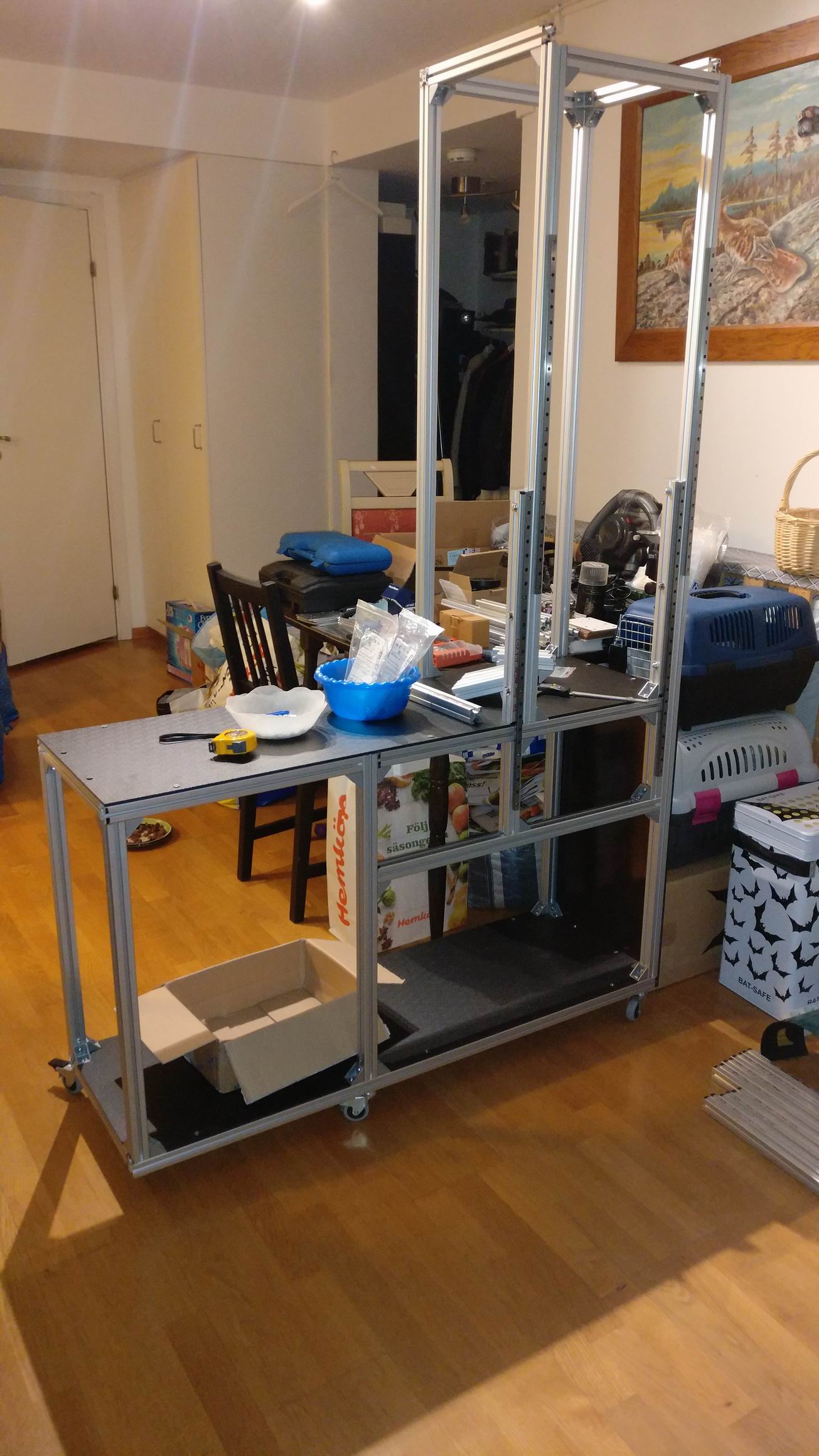
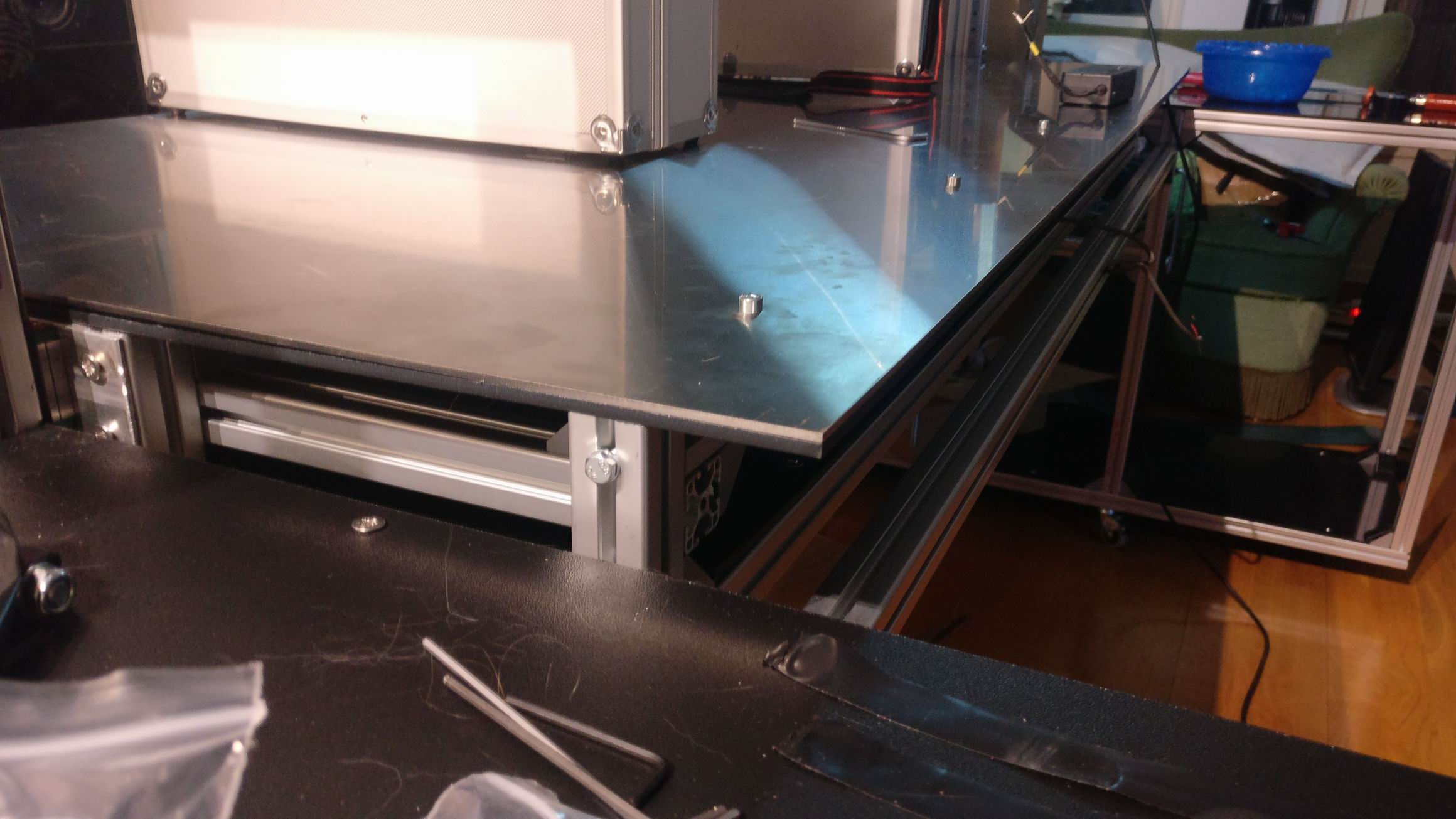
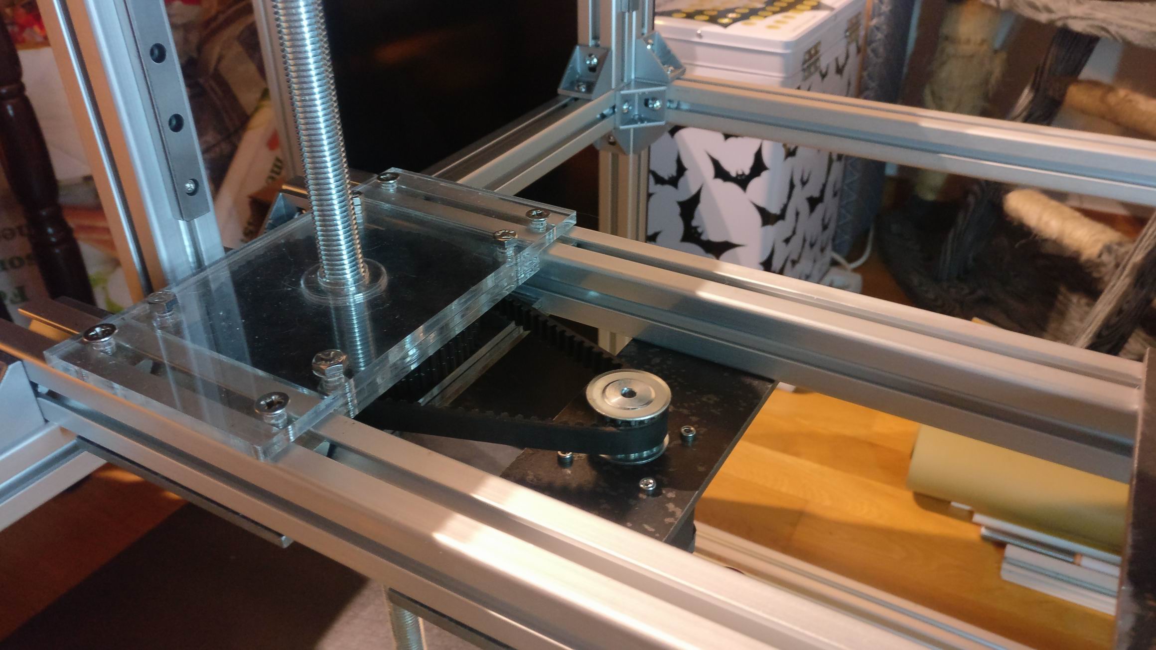
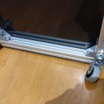
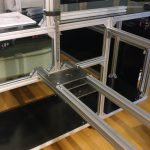
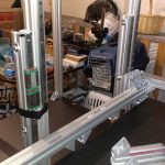
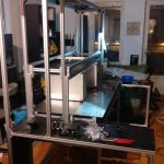
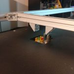
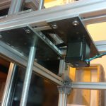
Sliders for the raise-able desk and shelf are mounted on the sides. It’s MGN12H linear sliders often used in smaller CNC builds.
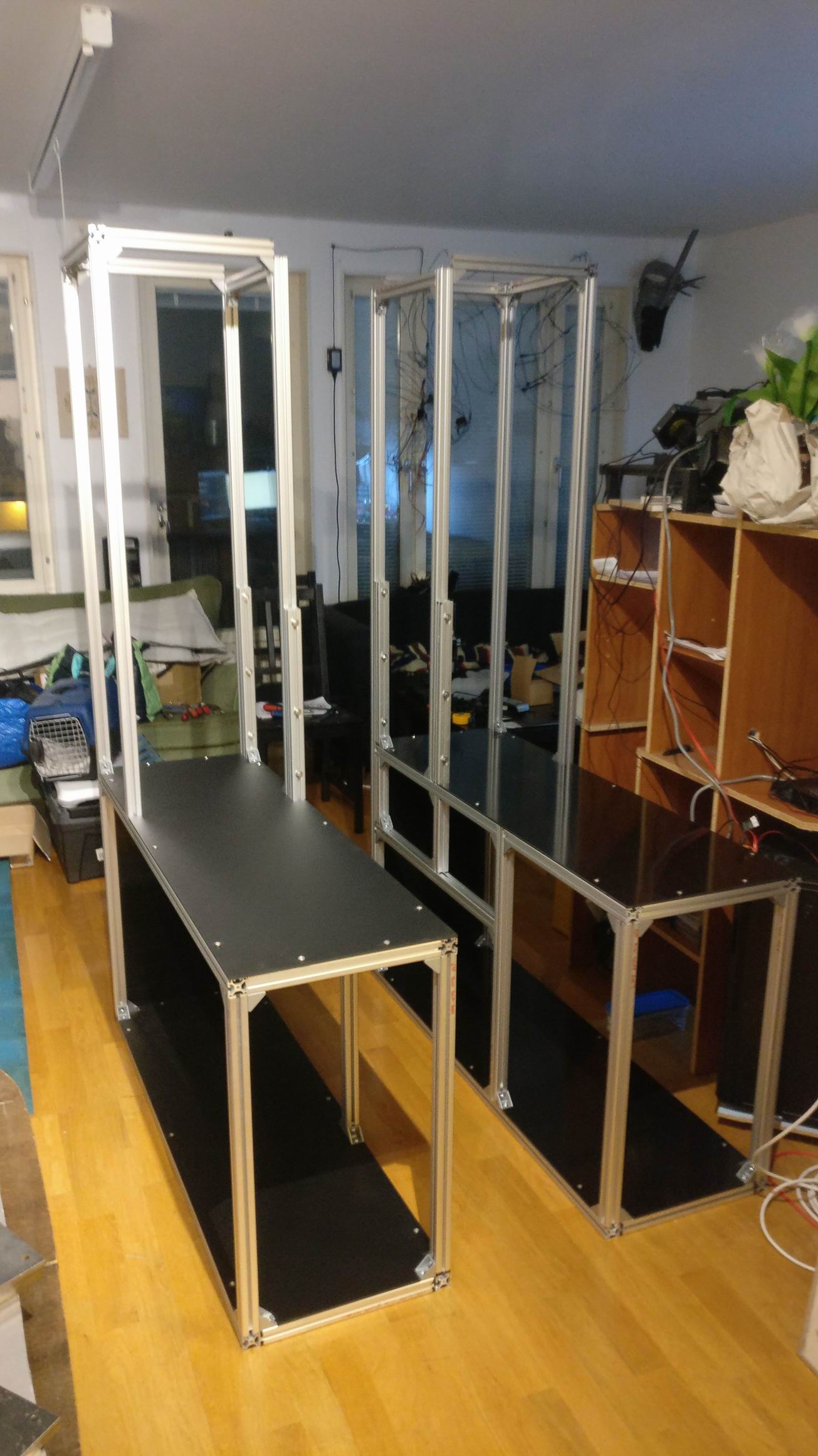
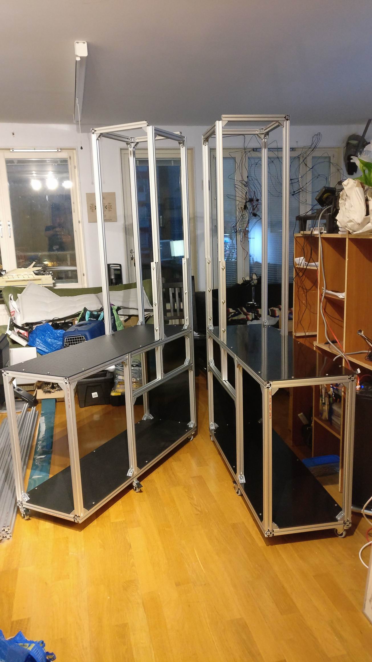
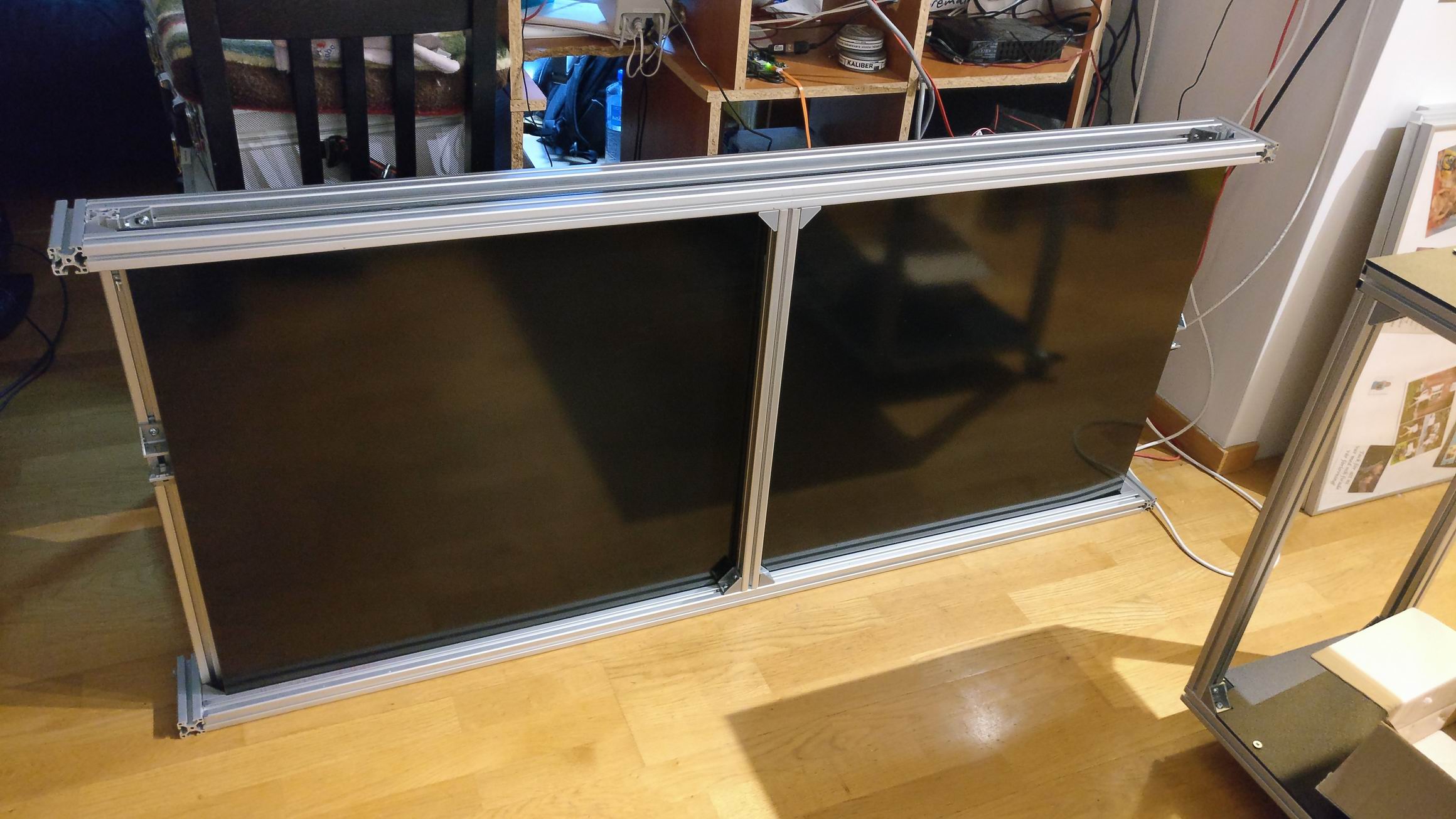
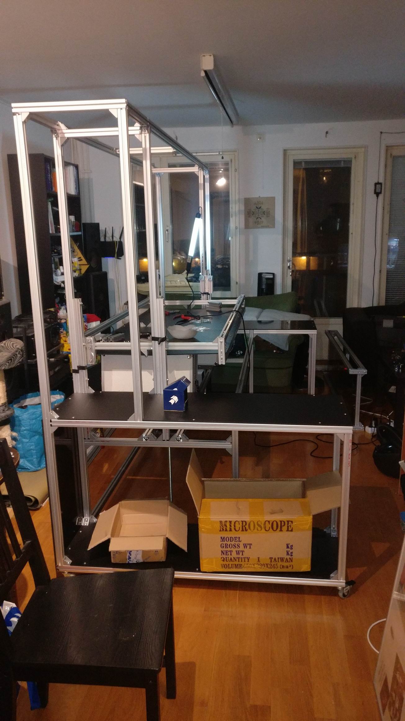
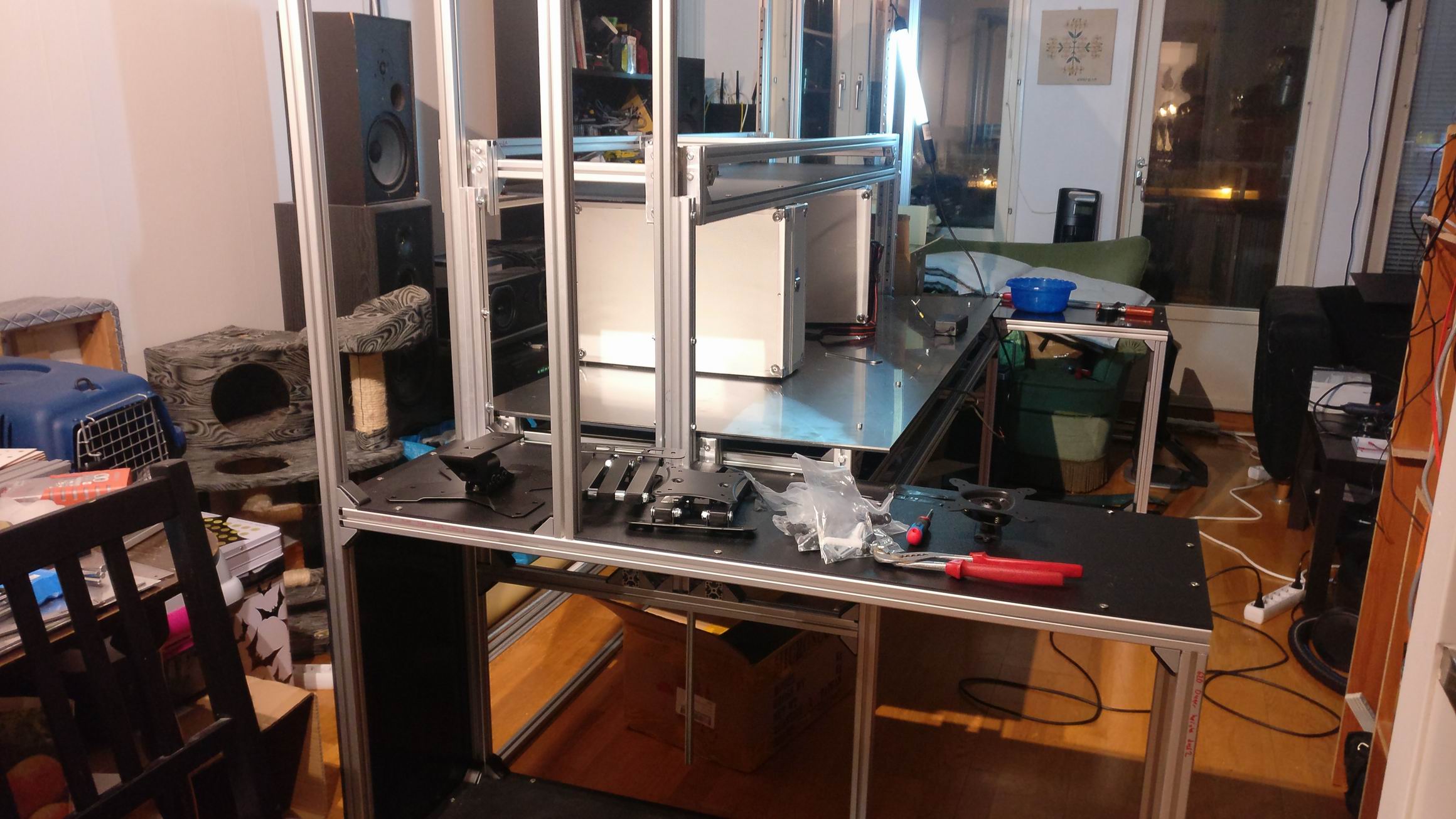
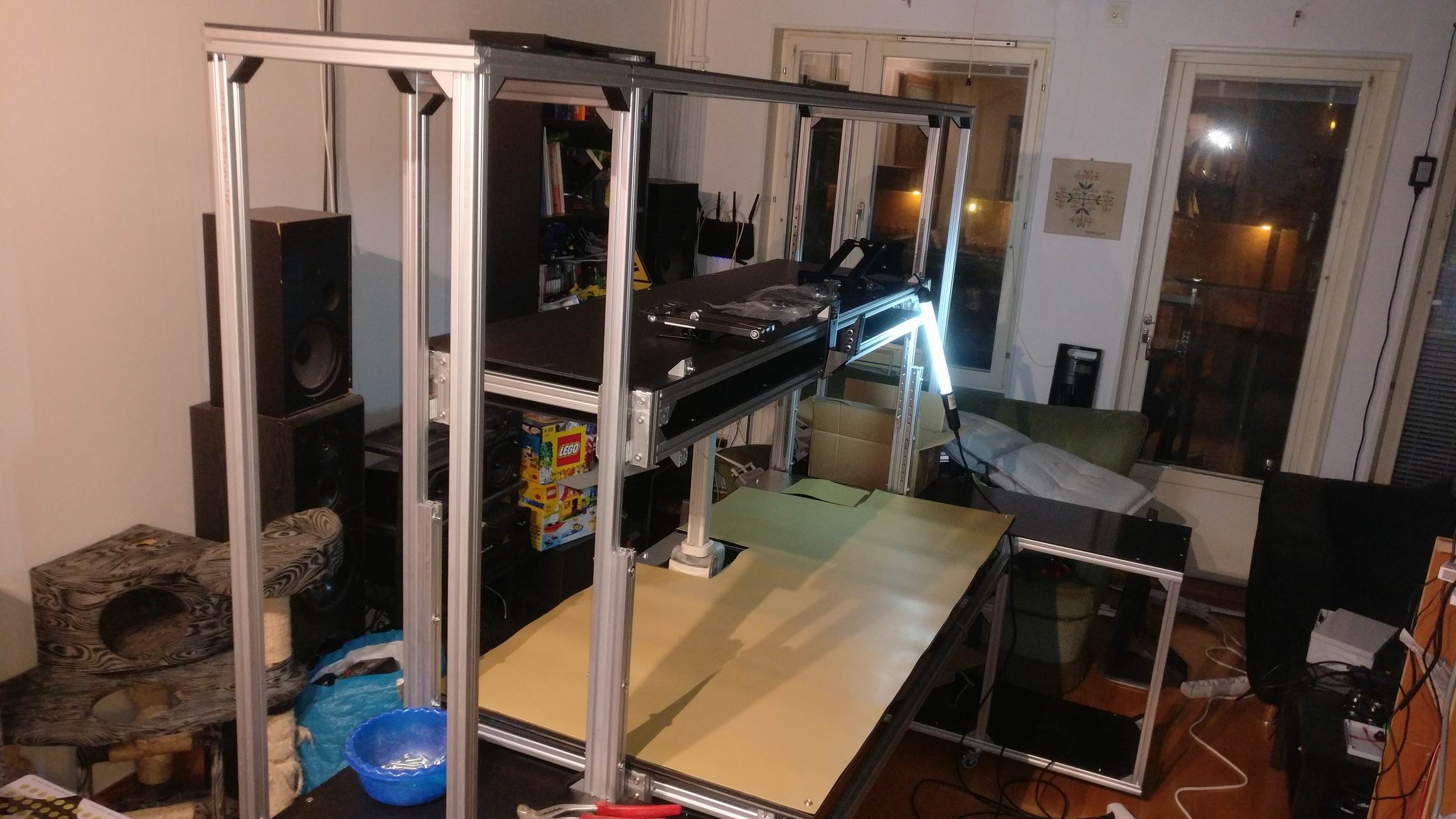
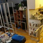
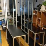
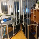
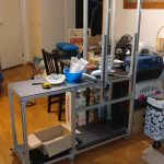

Desk assembled.


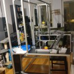
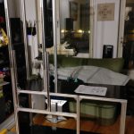
Center pieces to hold the two sides together.


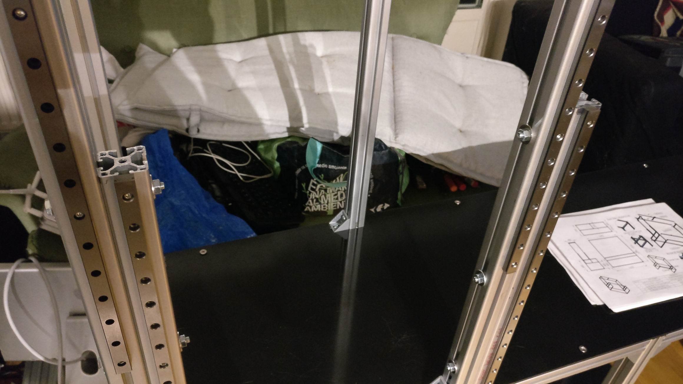
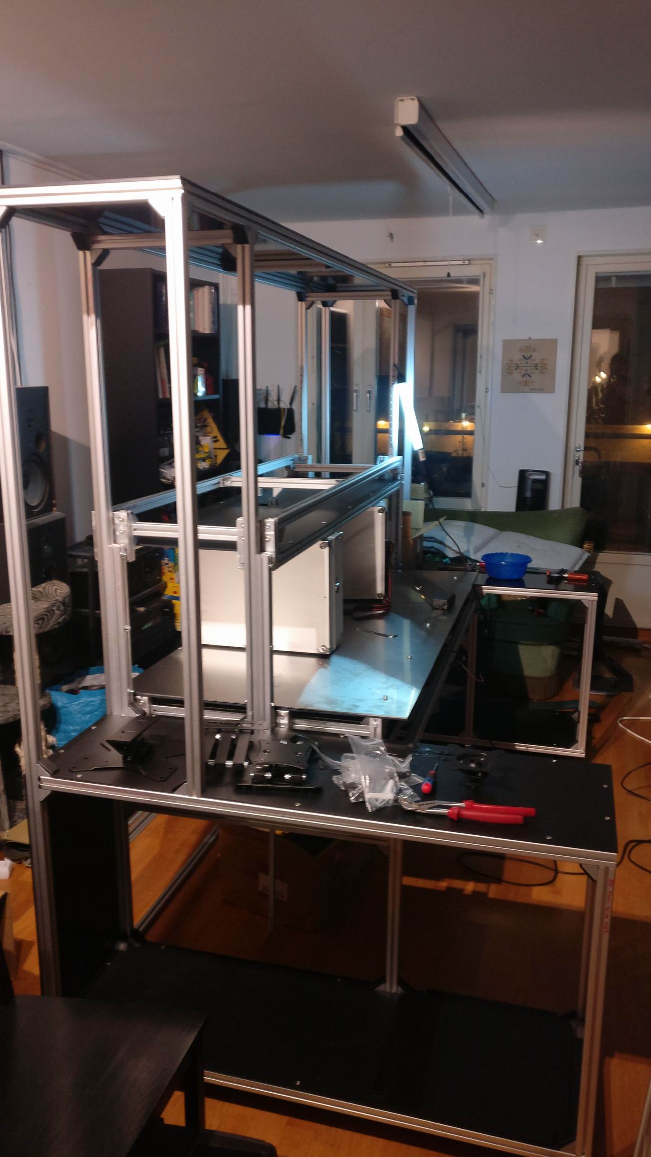
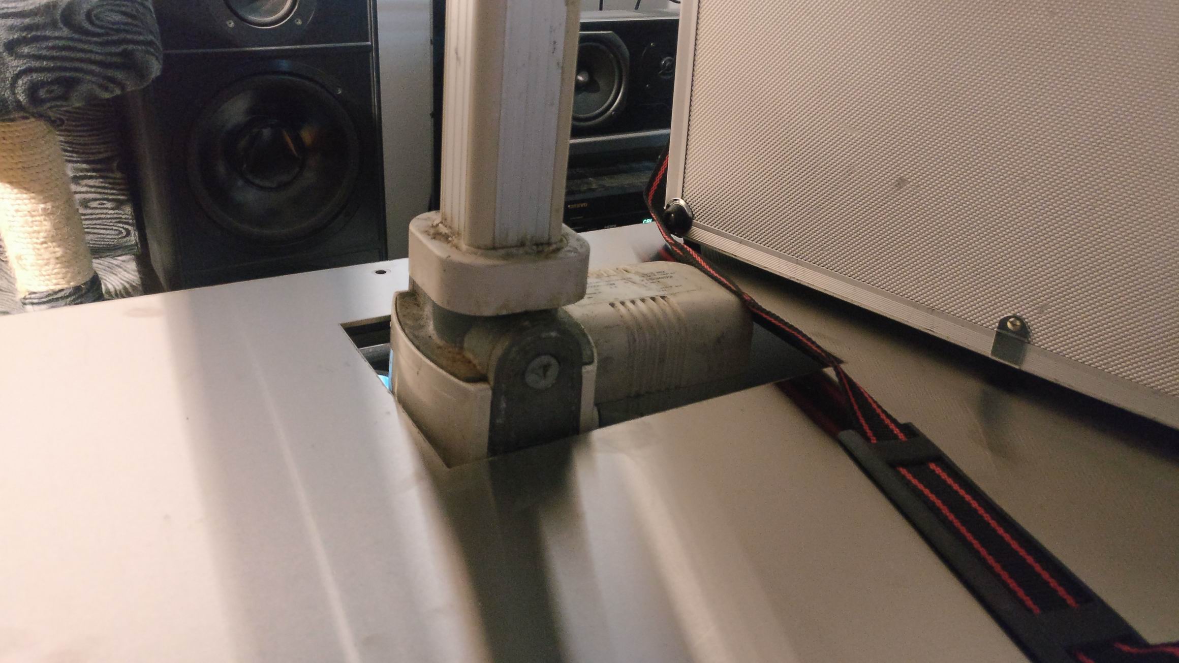
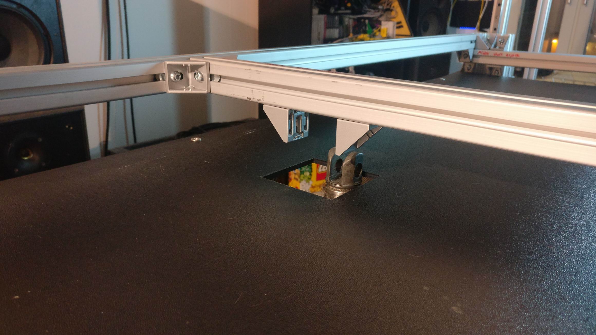
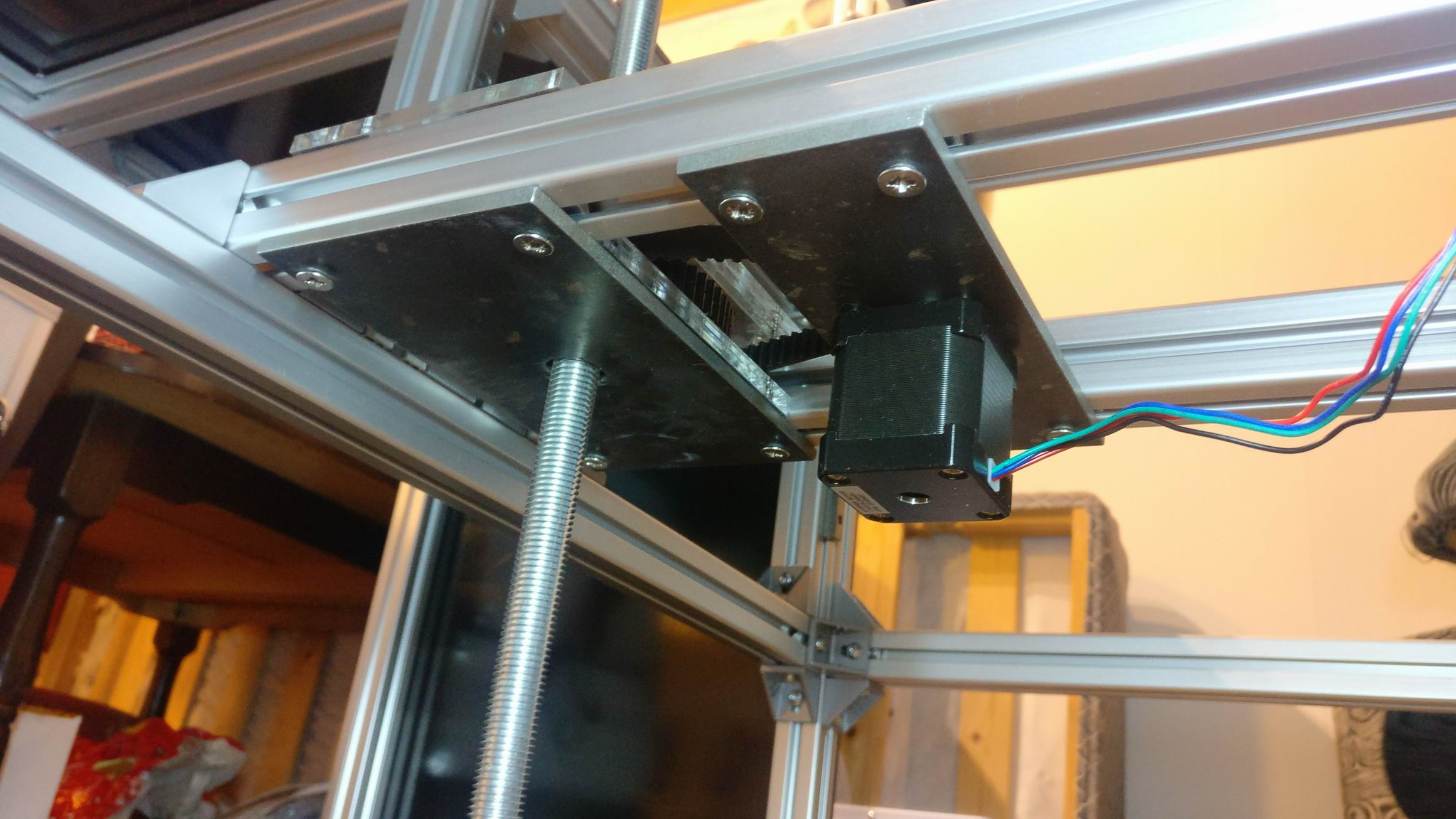
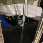
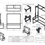
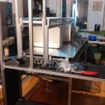
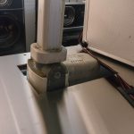
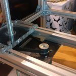
To make the desk move up and down in the sliders I’ve constructed a linear actuator using a threaded rod, some pulleys and a stepper motor. It all goes together in this lower center assembly.


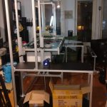
The desk was lifted in place and screwed into the MGN12H blocks. It should have been a lot of over constrains in the desk assembly, but it could move up and down pretty easy.


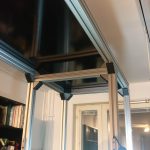
The desk shelf will hold all the monitors, and is attached to the big desk. That means when the desk is raised or lowered the computer monitors will follow. I used an old used actuator for this purpose that I had laying around.


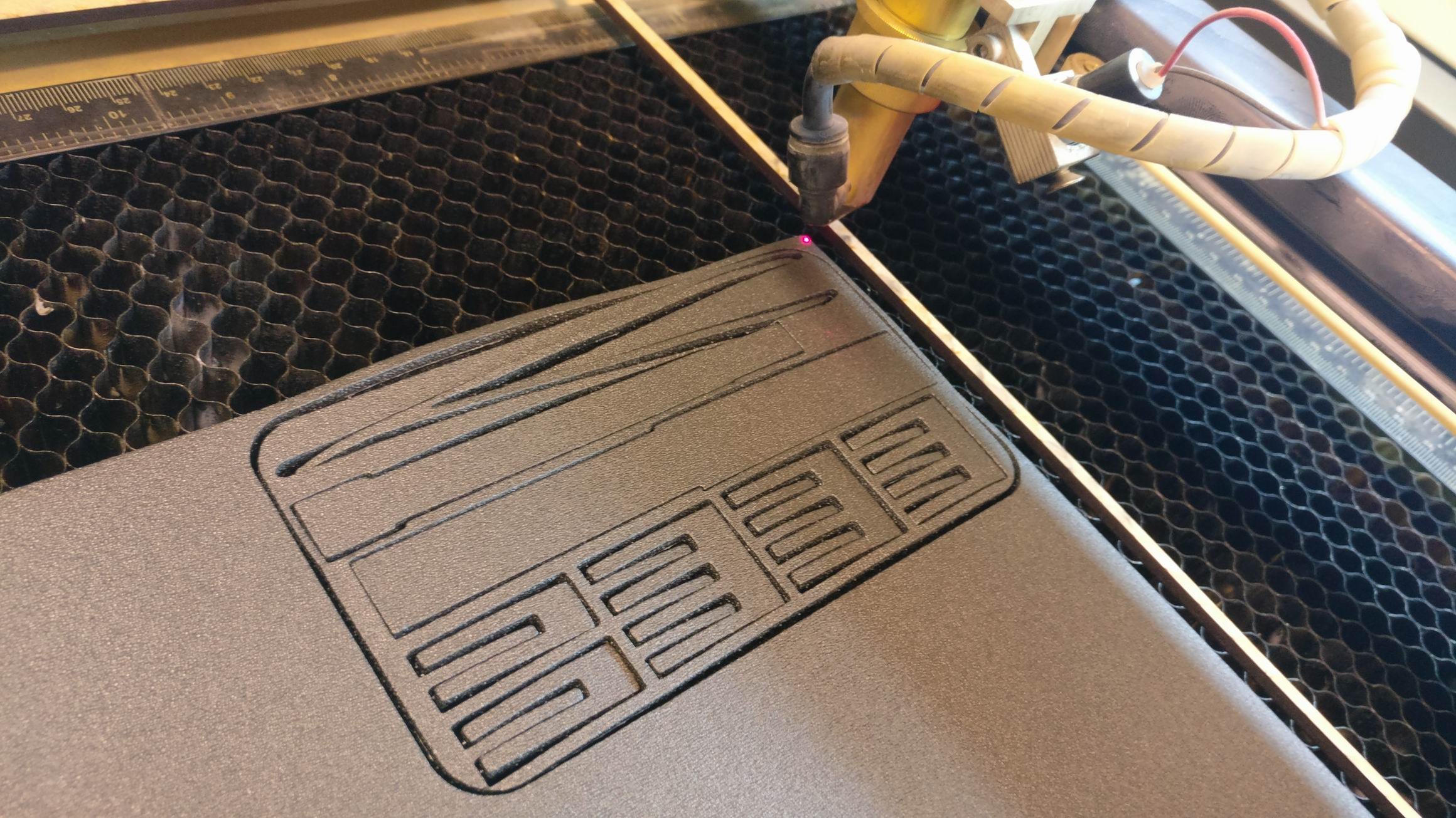
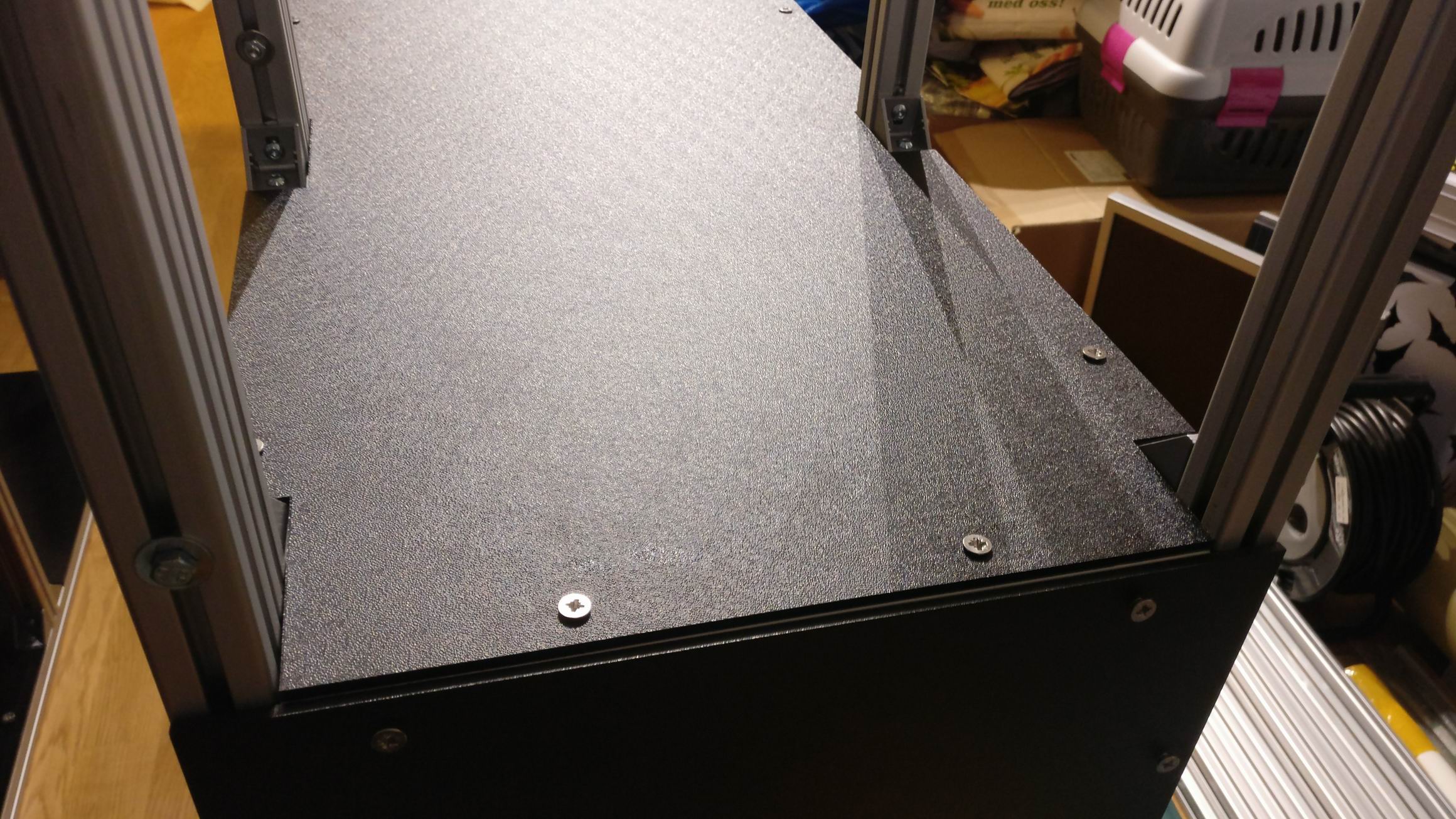
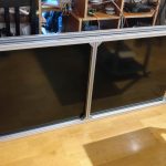
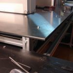
Instead of using CNC cut polycarbonate I ordered laser cut ABS sheets for the desk because it was a lot cheaper. I found this neat laser cut order system where I could upload my DXF-files directly on the web and isntantly get a quote. https://smidyo.com/


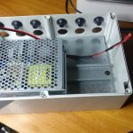
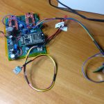
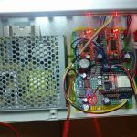
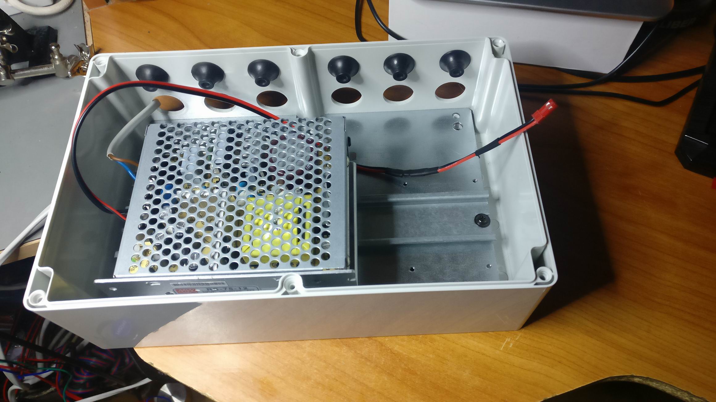
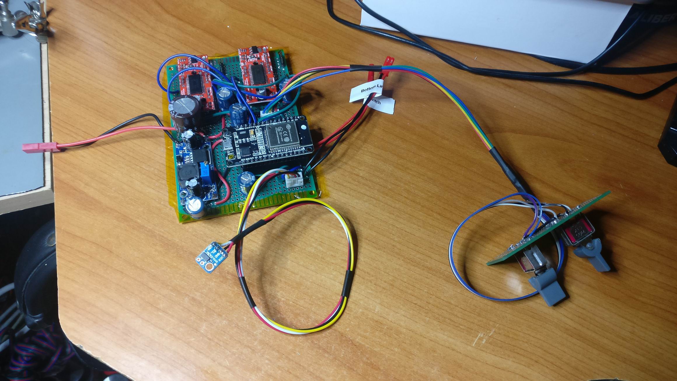
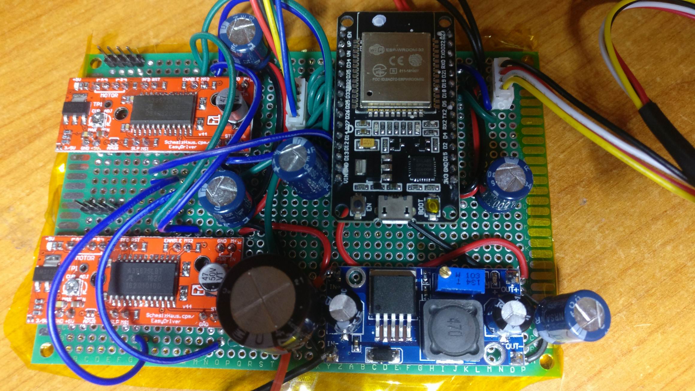
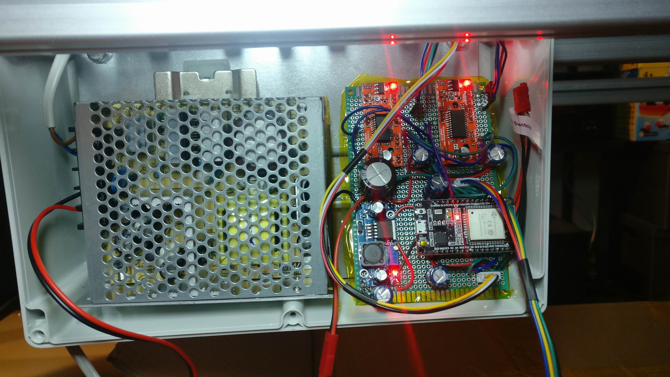
To raise and lower the desk I made a small control box. It have two stepper drivers inside that drives each side of the desk.
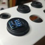
A VL53L0X ToF (Time-of-Flight) sensor is measuring the distance to the desk so the control box can regulate the height. This also gives me an absolute height of the desk when restarting the MCU.
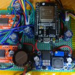
An ESP32 connects to a MQTT server and serves a desired height topic, when a new goal is set the control box will start to raise/lower the desk until the goal is set.
https://github.com/TimGremalm/SkrivbordDeskStepper
There’s also manual override for the desk with ordinary switches.

So in the end, was it worth it? No; the whole construction ended up far too expensive both in cost and time. But it was a nice experience to design something this big and follow through building it.
A far more effective workstation would be to purchase a cheap Ikea shelf and then place a raisable desk in front of it.

Prop Interactive Water effecet lamp


For the larp Do Androids Pray? we wanted to recreate the companys corridor scene from Blade Runner 2049 where some beautiful water light seemed to follow the persons who walked up the stairs.

I thought that it would be doable using multiple water effect light and dim them up when movement was detected.


I purchased some cheap water effect lamps of eBay and took them apart to inspect. The LED was hooked up to some mosfets, så I just removed the resistor leading to the original MCU and hotwired some leads to my own MCU.


I drilled out a small cut out for a 3 pin header an glued it into place and put a PIR module in.


The whole assembly kind of look like it’s original except an exposed PIR module.

Prop Sign “Rund” for the larp Do Androids Dream?

IMG_20170204_023729IMG_20170204_023728
For the larp Do Androids Dream we needed a lot of small props to give a Blade Runner feeling of the scene.
Small lit up signs would give that Hong Kong look that is so common in Blade Runner. Carl Nordblom, the set designer, had some ideas about how the sign should look, and had found some sample pictures.

IMG_20170204_023730IMG_20170204_023756
From the sample pictures I got an idea of how to produce a design. And from that idea I started to make a CAD-design.
The finished design ended up being almost exactly like the CAD-design.
Here is the Drawing of the Round Sign (Do Androids Dream).pdf

IMG_20170204_023731
IMG_20170204_023732IMG_20170204_023733
Small wooden block for holding a aluminium plate in a slot.

IMG_20170204_023735
IMG_20170204_023736IMG_20170204_023737IMG_20170204_023738IMG_20170204_023739IMG_20170204_023740
IMG_20170204_023742
The wooden blocks attached on to a sheet of flexible PET plastic.
The sheet is bent around the round aluminum plate with the help of the slots.

IMG_20170204_023743
The PET ring is transparent with a blue tint which would not be fitting in a light fixture. So we painted the PET ring in black to make it opaque.

IMG_20170204_023744IMG_20170204_023745IMG_20170204_023746IMG_20170204_023747
Warm white 5050 LED strip was glued on to the aluminium plate.
9×6 strips with 54 LED’s on each side makes 108 LED’s in total
108 * 20mA = 2.16A
2.16A * 12V = 26W

IMG_20170204_023749
IMG_20170204_023748IMG_20170204_023750IMG_20170204_023751
The LED strips is driven by 12V that comes in from JST-connector.
But the sign is supposed to look like an old florescent light, so to give that look the light should look like it flicker occasionally.
I hooked up an N-channel MOSFET IRLML6344 and connected it to a Arduino Nano for timing the random flickering.

IMG_20170204_023752
A big steel angle attached to the heavy aluminium plate of the sign, this is used for screwing the signs to a wall. Also the JST power connector, hidden in black heat shrink tubing.

IMG_20170204_023755
IMG_20170204_023753IMG_20170204_023754
In the outer sides of the sign round white acrylic plates will be inserted. They will rest against the wooden blocks and hold back by small sprints.
Each side of the sign is mirrored, so one sign have two faces.
The light is powerful enough to project through the white acrylic plastic. And with opaque paint on top will make a huge contrast perfect for a sign.

Prop Dragon in Noodle Bar for the larp Do Androids Dream?

IMG_024056
For the larp Do Androids Dream we needed a lot of small props to give a Blade Runner feeling of the scene.
An iconic part of the movie is the dragon sign above the Noodle Bar. I thought i could be made out of el wire and it could, it even looked like neon. The light emitting from the el wire was really low doh, I would prefer to have stronger light.

IMG_024057
I started out by placing steel wire in the dragons shape by hand.

IMG_024058
Attaching el wire around the steel wire frame was quite easy, just a matter of placing some transparent tape around it.

IMG_024059
When trying out the outer shape I know I was on the right track, it looked great!

IMG_024060
IMG_024061IMG_024062IMG_024063
The dragons tongue is animated in the movie, it’s animated in segments. I was after the same look, so I created two segments for the tongue and had the idea the enabling each segment by turning on and off the high voltage el wire transformers.
I connected a couple of N-channel MOSFET IRLML6344 and connected it to a Arduino Nano.

IMG_024064IMG_024065IMG_024066

µMute – A microwave oven silencer


I’m tired of the buzzer in the microwave oven that is beeping constant up to a minute.
IMG_20170122_0001

IMG_20170122_0002IMG_20170122_0003
So I opened it up like any normal hacker would, found the buzzer and snapped it off.

IMG_20170122_0005
IMG_20170122_0004
Sure, the buzzer was irritating, but so would be not to hear when my food is cooked. So i quickly had a look at the PCB and find a very interesting pinout.

IMG_20170122_0007
IMG_20170122_0006
So I soldered on some pins and started to measure the voltage level.
VCC of 5V looked promising for a microcontroller.

IMG_20170122_0009
IMG_20170122_0008
I had a look at the buzzer signal, it was a 2kHz signal with an amplitude of 5VDC.

IMG_20170122_0010
I had a rough idea in mind about having a small tune play instead of the 2kHz tone, and it should only play once.
So I shuffled some code together to code to play a small tune from the flash of an Arduino Nano. The flash could only hold about 18k of samples and was played at 8kHz.
https://github.com/TimGremalm/MicroMute
(inspired by http://playground.arduino.cc/Code/PCMAudio)
In lack of a better choice i choose Windows XP’s startup sound.
I shuffled some more code around to sample the original buzzer signal from a GPIO. If the sound is playing at more than 2kHz for a certain time I would trigger the sound.
I applied some time based software filters to filter out some noice.
I build a small amplifier out of an MOSFET (IRLML6344) and a small 0.5W speaker element I found at my local hackerspace.

IMG_20170122_0011
I throw it all into the chassis of the microwave oven. There was plenty of space, but i took some precautions to electrically isolate the PCB and speaker.

Unfortunately the sound from the small 0.5W element was too low. It barely was distinguishable against the sound of the microwave ovens fan.

IMG_20170122_0014
IMG_20170122_0015IMG_20170122_0012IMG_20170122_0013
IMG_20170122_0017IMG_20170122_0018
So I upgraded the element for a 3W element that I found in an old PC speaker, and took some precautions and upgraded my amplifier as well for the more stable Class-D amplifier PAM8403.

MicroMuteSchematic.sch
Schematic PDF

The sound was much louder and you can clearly hear the “Done”-sound from the microwave oven.

Festivalljus – LED, Lens, Heatsink Assembly

Assembly Spotlight With Chassi 3D 1
One of the hardest things with this project is to solve the problem with the heating. 9 pieces of 3W LED tends to get very hot, 27W that have to be transferred to the air.

LED 3DLED Inverted 3D
If I bend the pins on the led I can make the LED’s go through the PCB. An alternative is to use a lot of small via’s under the LED to transfer the heat to the underside. But I think a direct contact with the heatsink will be more effective.

Assembly PCB with LEDs 3D Without Lens
Assembly PCB with LEDs BottomAssembly PCB with LEDs 3DAssembly PCB with LEDs SideAssembly PCB with LEDs Top

Assembly PCB with LEDs 3D With Heatsink Fan
Assembly PCB with LEDs 3D With Heatsink LensesAssembly PCB with LEDs 3D With Heatsink Side
A CPU cooler should be sufficient enough to transfer the heat out to the air. I don’t know if the fan is necessary.

The whole assembly will look something like this:
Assembly Spotlight With Chassi 3D 2Assembly Spotlight With Chassi 3D 3Assembly Spotlight With Chassi 3D 4

Optics Specification